
Core and Cavity Insert Sets, Built From Your Drawing
Submit your drawing for DFM review, process planning, and inspected core and cavity insert sets matched to critical dimensions and quality requirements.
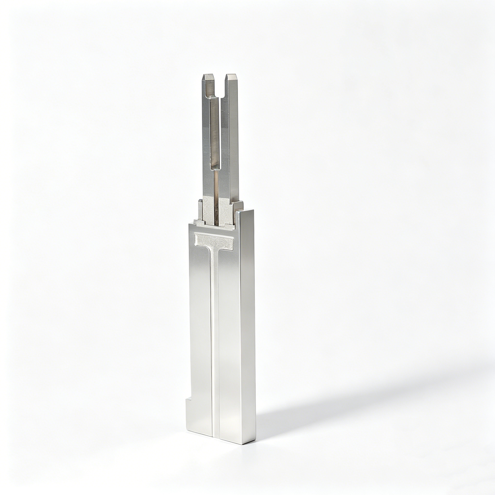
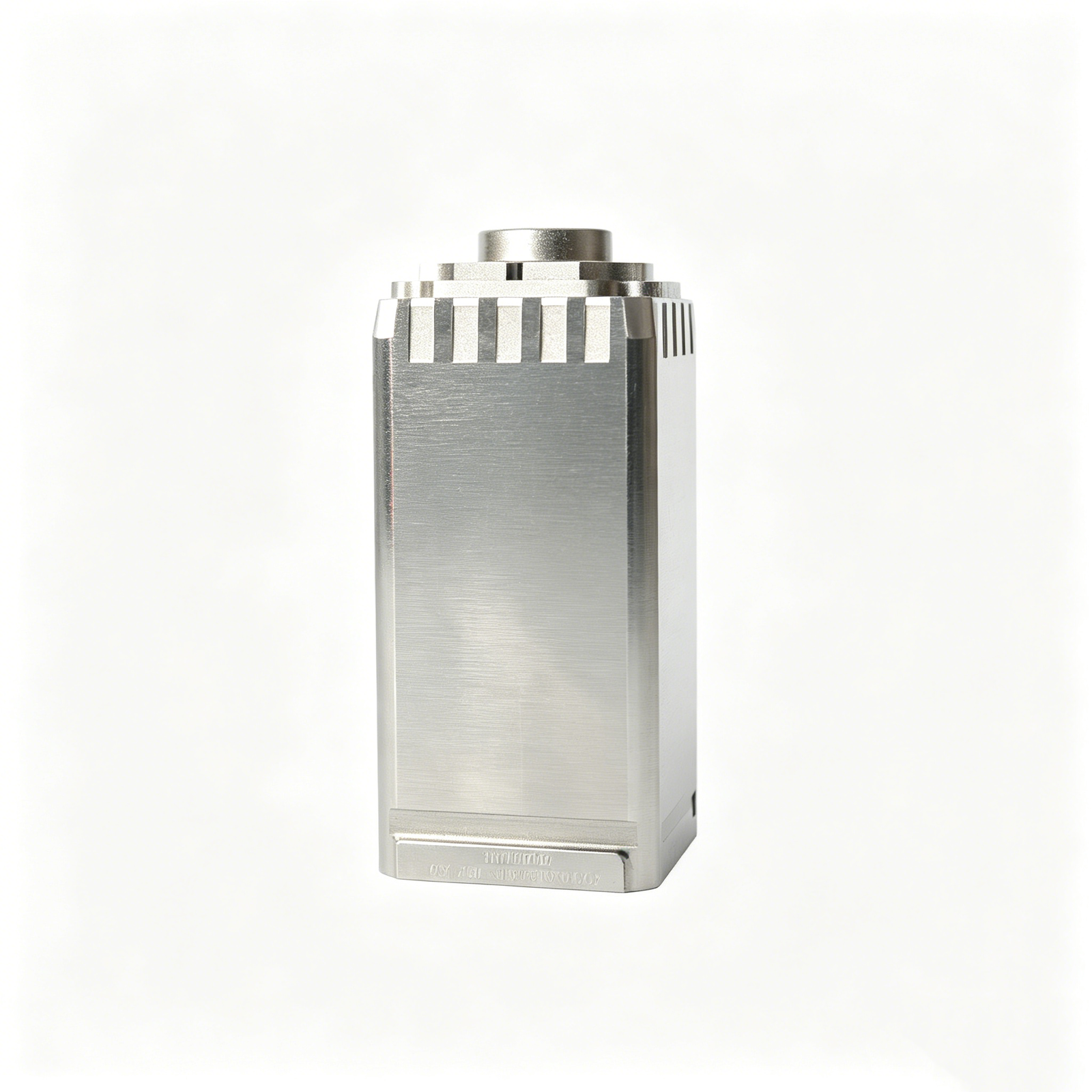
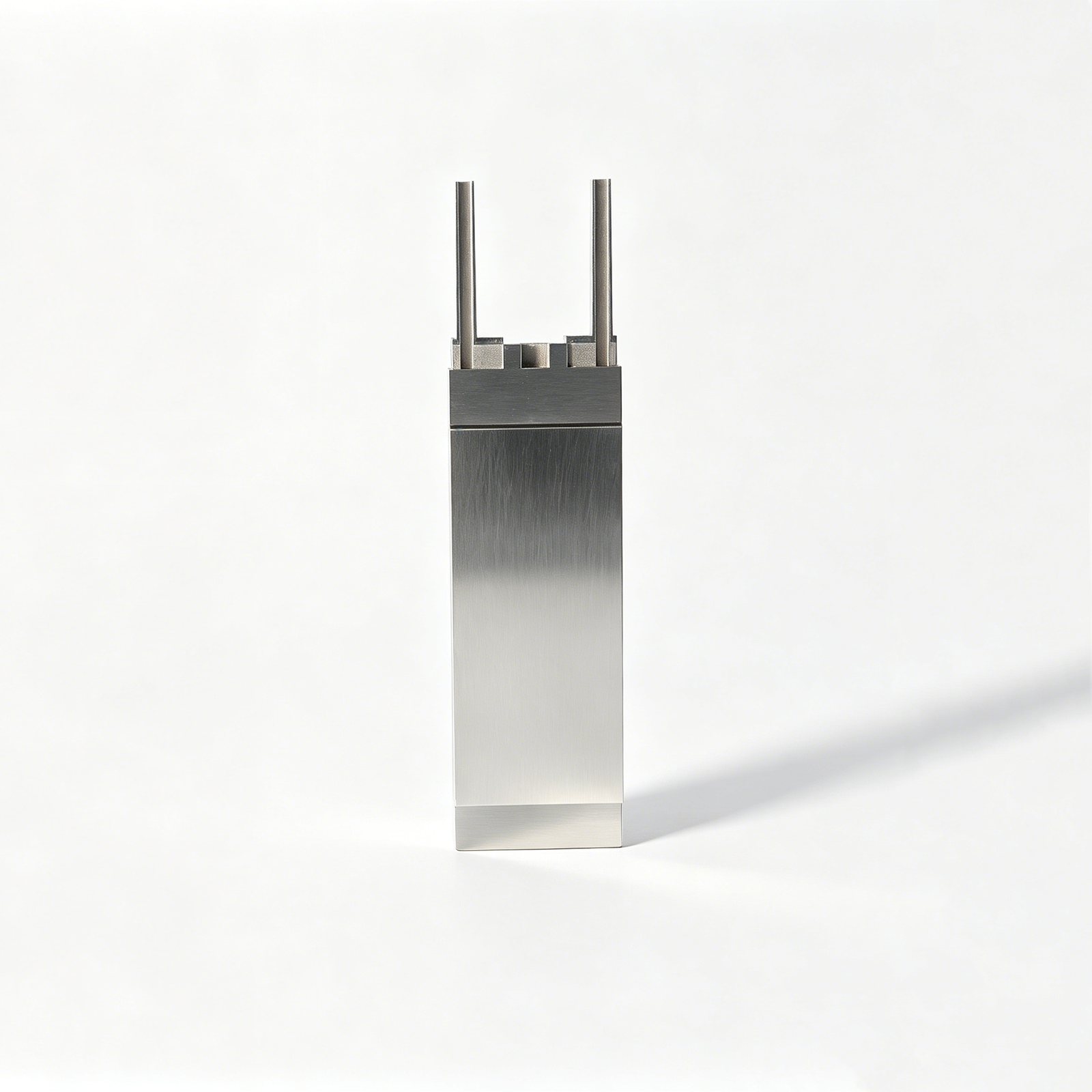
Representative Core and Cavity Insert Sets









Related Product Families and RFQ




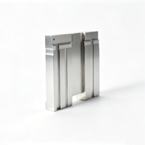
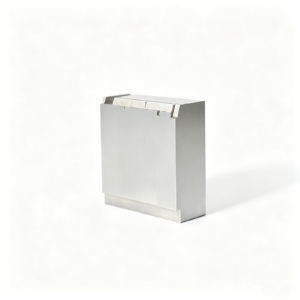

Core and Cavity Insert Sets: Engineering Advantages
Drawing-led planning aligns DFM, process routing, critical dimensions, inspection requirements, and revision control before production commitments are made.
Drawing-Led DFM Review
We review geometry, datums, machining access, and tolerance priorities for core and cavity insert sets before quoting the proposed route.
Integrated Process Planning
CNC machining, EDM, grinding, and fitting are sequenced around geometry, material condition, surface requirements, and practical manufacturing access.
Critical Dimensions First
Project discussions identify critical-to-quality features, datum relationships, and inspection methods so measurement expectations are visible before production begins.
EDM and Grinding Strategy
Electrode needs, wire paths, heat-treatment sequence, and grinding stock are considered when complex features or finishing requirements influence the route.
Inspection Matched to Order
Inspection planning is aligned with the drawing and agreed requirements, with final documentation matched to the verified order scope.
Visible Revision Control
Revision information and delivery coordination remain traceable throughout the project, helping teams manage drawing updates without losing manufacturing context.
Core, Cavity and Precision Tooling Families
Drawing-driven machining, tooling and inspection routes for configurable precision components, from DFM review through documented delivery.

CNC Machining Services
Precision CNC machining services for drawing-based parts requiring coordinated milling, turning, EDM, grinding and inspection. RFQ review should identify material, critical dimensions, datum references, surface requirements, quantity and required documentation before a process route is confirmed.
Upload a Drawing
CNC Milling
Custom CNC milling services for prismatic mold components, inserts, plates, slides and custom machined features. Tool access, clamping strategy, corner radii, stock condition and datum sequence should be reviewed against the drawing before machining commitments.
Upload a Drawing
CNC Turning
Precision CNC turning services for rotational components such as pins, sleeves, bushings, guide elements and custom shafts. Diameters, concentricity, runout, thread requirements, heat-treatment sequence and inspection points should be defined in the drawing review.
Upload a Drawing
5-Axis Machining
5-axis CNC machining supports complex surfaces and multi-face features where fewer setups can help protect positional relationships. Feasibility depends on tool reach, workholding, machine access, material condition, tolerances and the inspection method for critical geometry.
Upload a Drawing
Swiss & Micro Machining
Swiss machining and micro machining support small, slender, detail-intensive components where diameter control, feature access and handling require focused planning. Submit the drawing, material, quantity and critical tolerances so a suitable process and inspection approach can be assessed.
Upload a Drawing
Wire & Sinker EDM
Wire EDM and sinker EDM services address hardened materials, narrow slots, sharp internal geometry and features with limited conventional-tool access. Electrode strategy, wire path, corner requirements, recast-layer considerations and finish expectations should be agreed before production.
Upload a Drawing
Precision Grinding
Precision surface and profile grinding supports flatness, parallelism, profile control and controlled finishing after machining or heat treatment. Grinding stock, datum surfaces, distortion risk, material condition and measurement requirements should be established in the process plan.
Upload a Drawing
Mold Core & Cavity Inserts
Precision mold core and cavity inserts are manufactured from customer drawings for injection-mold tooling applications. Review focuses on shutoff geometry, cooling or feature access, steel and heat-treatment requirements, EDM needs, mating relationships and inspection criteria.
Upload a Drawing
Ejector & Ejection Components
Ejector pins, sleeves and ejection components are configurable drawing-based parts for mold ejection systems. Diameter fit, clearance, stroke-related interfaces, material and hardness requirements, surface condition and mating-component information help determine the manufacturing route.
Upload a Drawing
Core Pins, Guide & Locating Components
Core pins, guide pins and locating components require careful control of functional diameters, alignment features and mating fits. SUUXIANG reviews datum strategy, wear surfaces, material condition, heat treatment and inspection requirements before proceeding with a production plan.
Upload a Drawing
Slides, Lifters, Gates & Mold Accessories
Mold slides, lifters, gates and accessories are produced as configurable tooling components based on drawings and interface information. Travel geometry, shutoff faces, wear conditions, lubrication provisions, machining access and fitting requirements should be clarified early.
Upload a Drawing
Connector Mold Components
Precision connector mold components support tooling for connector-product features where small geometry, cavity alignment and repeatable interfaces matter. Drawings should identify critical mating dimensions, material, finish, EDM or grinding needs, inspection priorities and revision status.
Upload a Drawing
Stamping Die Components
Precision stamping die components are manufactured for drawing-driven die assemblies, including punches, inserts, guide elements and formed profiles. Material, hardness, wear conditions, clearance relationships, grinding stock and dimensional reporting requirements guide process planning.
Upload a Drawing
Injection, MIM, CIM & Overmolding Tooling
Injection, MIM, CIM and overmolding tooling work is considered when requirements fit verified production scope. Provide the component drawing, material, molding context, critical interfaces, anticipated wear conditions, quantity and inspection expectations for a responsible assessment.
Upload a Drawing
Machining Materials
CNC machining materials are selected against drawing requirements, functional loads, corrosion exposure, wear, heat treatment and finishing needs. Specify the material grade and condition where available; substitutions or alternatives should be reviewed and documented before production.
Upload a Drawing
Surface Finishes & Heat Treatment
Surface finishing and heat treatment are planned around functional surfaces, corrosion resistance, wear, dimensional change and post-process inspection. Requirements should state the intended treatment, finish areas, masking needs, hardness expectations and any dimensional priorities after processing.
Upload a Drawing
Quality, Metrology & Documentation
Precision inspection, metrology and quality documentation are matched to the order’s verified inspection plan. Define critical dimensions, datums, reporting format, sampling expectations, traceability needs and any customer-specified measurement method during RFQ review.
Upload a Drawing
Prototyping & Low-Volume Production
Rapid prototyping and low-volume manufacturing support drawing-based validation parts and controlled small-batch requirements. Early review addresses material availability, manufacturability, critical dimensions, revision control, inspection scope and target delivery date before production is scheduled.
Upload a DrawingMaterial Options for Core and Cavity Insert Sets

P20 Prehardened Steel
Often considered for general-purpose mold inserts where machinability and a practical hardness condition matter. Confirm the required steel designation, starting condition, machining allowance, and any post-machining treatment against the drawing and application.

H13 Tool Steel
A tool-steel option commonly evaluated for inserts exposed to elevated temperatures, cyclic loading, or wear. The required heat-treatment sequence, hardness range, EDM strategy, and grinding stock should be defined before production planning.

Stainless Tool Steel
Stainless steel grades may be evaluated where corrosion resistance, polishability, or molding-environment conditions are material selection priorities. Confirm the exact grade, heat-treatment condition, surface requirement, and critical dimensions with the project documentation.

Copper Alloy
Copper-alloy inserts can be considered for localized thermal-management needs, subject to geometry, strength, wear, and mating-component requirements. Review support features, machining access, joining approach, and inspection criteria before committing to the material route.

Customer-Specified Grades
SUUXIANG reviews customer-specified material options against the drawing, application, quantity, and quality requirements. Provide material standards, certificates where needed, heat-treatment details, and functional context so the proposed process route can be assessed.
Core and Cavity Insert Sets: Process Routes


Wire EDM
Wire EDM is applied where through profiles, narrow slots or sharp internal geometry cannot be reached reliably by cutting tools. The wire path, start-hole position and datum relationship are planned against functional dimensions.

Sinker EDM
Sinker EDM forms deep cavities, fine ribs and detailed internal features requiring shaped electrodes. Electrode strategy, spark allowance and surface requirements are reviewed so the result supports later fitting and inspection.


Fitting and Inspection
Fitting confirms mating relationships, movement and contact conditions between insert components. Inspection is planned around critical dimensions, agreed datums and reporting needs, with revision information kept visible throughout the project.

Surface Finishing
Finishing addresses specified surface condition and prepares functional areas for their intended molding or assembly role. The required finish, edge condition and any treatment sequence should be confirmed from the drawing and application context.
Core and Cavity Insert Sets: Assembly Features

Locating Components
Locating pins, dowels, and datum features help establish repeatable alignment between core and cavity insert sets, mold plates, and mating components. Define datum references, fits, material, and assembly orientation in the drawing.

Guide Elements
Guide pins, bushes, and wear-guided features support controlled relative movement during mold operation. Their selection depends on stroke, load path, lubrication, clearance, and the relationship between the insert and surrounding mold structure.

Ejection Components
Ejector pins, sleeves, blades, and return-related parts can be supplied as drawing-defined mold components. Review ejection contact areas, clearance, hardness sequence, surface requirements, and fitting needs before committing the process route.

Fastening Hardware
Screws, clamps, retaining features, and threaded interfaces secure inserts within the assembly. Confirm thread standards, access direction, tightening constraints, counterbore details, and whether hardware is customer-specified or included in the manufacturing scope.

Identification Marking
Part numbers, revision marks, cavity identifiers, and orientation references improve assembly control and traceability. Specify marking method, location, character size, and visibility requirements so identification does not interfere with functional surfaces.

Fitting Features
Relief pockets, assembly clearances, anti-rotation geometry, and controlled interfaces support practical fitting of core and cavity insert sets. Share mating-part models and critical contact requirements to evaluate tool access, grinding stock, and inspection method.
Core and Cavity Insert Sets at SUUXIANG
SUUXIANG is the sole public-facing brand of Dongguan SuuXiang Precision Mold Co., Ltd., established in 2010 in Chang’an Town, Dongguan, Guangdong, China. Founded by XiaoCheng Huang, the company helps global teams translate drawings, 3D models, and technical requirements into inspected core and cavity insert sets, precision mold components, connector tooling, and custom machined parts.
Our workflow begins with disciplined drawing review and DFM discussion. Before production commitments, we clarify critical dimensions, datums, material and heat-treatment requirements, machining access, EDM or grinding needs, surface priorities, inspection expectations, revision status, and delivery requirements.
SUUXIANG brings CNC milling and turning, multi-axis machining, EDM, precision grinding, fitting, and inspection into a controlled manufacturing route. Rather than treating an RFQ as a generic quote, we focus on process choices, traceable communication, and documentation aligned with the agreed inspection plan.

Core and Cavity Insert Sets: From Drawing Review to Inspected Delivery
DFM and Datum Review
Before quoting core and cavity insert sets, SUUXIANG reviews the drawing, 3D model, functional datums, critical dimensions, surface requirements and mating context. The review identifies tolerance-stack risks, machining access and unresolved requirements that could affect the process route or inspection plan.
- Confirm datum scheme and critical-to-quality features
- Review tool reach, corner conditions and parting geometry
- Identify tolerance, finish and mating-interface priorities
- Align material, heat treatment and quantity requirements

CNC and EDM Strategy
The manufacturing route is selected around geometry, access and finish requirements rather than a default machine list. CNC machining establishes accessible form and reference features; wire EDM or sinker EDM can be considered where internal profiles, sharp details or restricted tool access require it.
- Plan roughing and finishing around stable reference surfaces
- Assess electrode needs for inaccessible cavity details
- Define wire paths for profiles and precision openings
- Review heat-treatment sequence and machining allowance

Grinding and Fitting Control
Grinding and fitting are planned as controlled finishing operations when the drawing and assembly relationship require them. SUUXIANG considers grinding stock, datum preservation, contact surfaces and assembly interfaces so finished inserts can be evaluated against the specified functional relationship, not only isolated dimensions.
- Reserve suitable stock before grinding operations
- Protect critical datums through process transitions
- Review shutoff, locating and mating contact areas
- Coordinate fitting requirements with drawing revisions

Inspection and Revision Traceability
Inspection planning starts with the drawing’s critical features and the agreed reporting needs. For each order, SUUXIANG aligns measurement methods, inspection points and documentation with the verified plan, while keeping revision status and delivery information visible throughout production coordination.
- Define inspection focus for critical dimensions and surfaces
- Match measurement methods to feature accessibility
- Confirm requested reports before production release
- Maintain drawing revision and order traceability

Why Choose SUUXIANG for Core and Cavity Insert Sets
Compare the engineering evidence needed before production begins.
← Swipe left or right to view →
Core and Cavity Insert Sets: Precision Manufacturing Workflow
A drawing-led workflow that keeps critical dimensions, process decisions, inspection requirements, revisions, and delivery coordination visible before production commitments are made.
Review RFQ Package
We review the 2D drawing, available 3D model, quantity, application, material, quality expectations, target date, and any mating-component information that affects manufacturability.
Define Critical Requirements
The team identifies critical dimensions, datums, surface requirements, tolerance stack risks, machining access, heat-treatment sequence, and the inspection evidence required for the order.
Plan Process Route
We determine the appropriate CNC milling, turning, multi-axis machining, EDM, grinding, fitting, and inspection sequence, including allowances, electrode strategy, and wire paths where needed.
Machine Insert Features
Core and cavity insert sets are produced to the approved drawing revision through controlled machining operations, with process decisions aligned to geometry, material condition, and functional interfaces.
Finish and Inspect
EDM, grinding, fitting, and finishing are applied as required. Inspection follows the agreed plan, focusing on specified dimensions, surfaces, datums, and documentation requirements.
Coordinate Delivery Release
Before release, we confirm the applicable drawing revision, inspection records, packing needs, and delivery details so your receiving team has clear project and traceability information.
Start Your Core and Cavity Insert Sets Project
Share complete requirements early so SUUXIANG can align manufacturability, inspection, revision control, and delivery expectations before production begins.
Submit Your Drawing Package
Provide 2D drawings, available 3D models, material and heat-treatment requirements, quantity, application context, critical dimensions, surface priorities, and target delivery date.
Review DFM and Requirements
Our engineering team reviews datum strategy, tolerance stack, tool access, machining allowance, EDM needs, grinding sequence, and inspection expectations before quotation.
Confirm the Production Plan
Review the proposed process route, commercial quotation, revision status, quality requirements, and any sample or first-article expectations before releasing work.
Coordinate Inspection and Delivery
Production follows the confirmed drawing and plan, with inspection documentation, revision visibility, packing requirements, and delivery coordination aligned to the verified order requirements.
Quality Documentation for Core and Cavity Insert Sets
Core and Cavity Insert Sets Customer Outcomes Pending Approval
No approved customer testimonial or project case summary is currently available for publication. SUUXIANG will add measurable outcome evidence only after the customer has approved the wording and disclosure level.
No approved customer testimonial or project case summary is currently available for publication. Any future statement will identify the verified engineering, inspection, or delivery outcome supported by project records.
No approved customer testimonial or project case summary is currently available for publication. SUUXIANG does not publish anonymized performance claims without source approval and supporting project evidence.
Core and Cavity Insert Sets FAQ
Practical answers for drawing-led sourcing, quality planning, and delivery coordination.
What information should I include in an RFQ for core and cavity insert sets?
Can SUUXIANG quote low-volume core and cavity insert sets?
How are core and cavity insert sets sampled before full production?
What affects lead time for custom mold inserts?
How do you control material and heat treatment for core and cavity insert sets?
Can I request an inspection report with my order?
How are core and cavity insert sets packed and shipped internationally?
How is drawing confidentiality and IP handled?
The Complete Buyer’s Guide to core and cavity insert sets
Use this practical decision framework to specify core and cavity insert sets, compare material and manufacturing options, vet CNC suppliers, control cost and lead time, and avoid drawing, tolerance, and quality-planning mistakes.
1. What Are Core and Cavity Insert Sets?
Two matched tool faces define a molded part: the cavity insert forms the external surface, while the core insert forms internal features, hollows, and much of the wall thickness. Together, core and cavity insert sets close around the parting line and create the molding volume.
One removable insert pair localizes complex or wear-prone geometry instead of committing every feature to the mold base. This makes design changes, polishing, repair, and replacement more targeted, while preserving the base for features that do not require frequent service.
Three interfaces deserve drawing-level attention: the insert seating datum, the shutoff or parting surfaces, and the cooling path. Their fit influences flash risk, heat removal, surface appearance, and interchangeability; SUUXIANG reviews these relationships from the drawing, model, material, and inspection requirements before selecting CNC, EDM, grinding, fitting, and inspection steps.
2. Evolution of Core and Cavity Insert Sets
Two-piece mold layouts gradually replaced reliance on a single integral block where a localized wear area, design change, or damaged detail could force extensive rework. Separating the forming geometry into replaceable core and cavity inserts made it practical to service the affected region while retaining the mold base and adjacent features.
Three process families now commonly divide the work: CNC milling establishes accessible bulk geometry, EDM produces deep ribs or sharp internal features, and grinding brings datum faces and fitting surfaces into final relationship. For buyers, the important question is not which machine is named, but whether the drawing identifies datum hierarchy, stock allowances, electrode or wire paths, and the dimensions to inspect after heat treatment.
One replaceable insert strategy can shorten a tooling revision because only the changed geometry may need remanufacture and refitting. That is especially useful in development-stage or low-volume work, where part geometry, gating, venting, or mating details may still change; interchangeability still depends on controlled interfaces, revision control, and an agreed inspection plan.
3. Types of Core and Cavity Insert Sets
Six configurations cover most core and cavity insert sets RFQs. Select by mold architecture, serviceability, and whether mating geometry must be manufactured and checked as an assembly.
| Configuration | Typical Geometry And Use | Advantage / Constraint | Drawing Information |
|---|---|---|---|
| Block inserts | Rectangular pockets; general mold faces | Simple location; corner access limits | Pocket datums, keys, parting surfaces |
| Round inserts | Cylindrical cores, necks, pins | Concentric; anti-rotation needed | Diameters, clocking, fit and seat |
| Multi-cavity sets | Repeated cavities in one tool | Output; cavity-to-cavity matching | Cavity map, interchangeability, matching datum |
| Interchangeable sets | Swappable variants or family tooling | Flexible; interface control critical | Common envelope, variant IDs, locating scheme |
| Insert-molding nests | Metal insert support and overmold location | Stable placement; insert tolerances matter | Insert model, contact points, loading direction |
| Wear or shutoff inserts | Replaceable sealing or abrasion zones | Serviceable; paired fit matters | Shutoff angle, contact band, assembly condition |
Paired Machining Requirements
Two mating inserts need shared datums when shutoffs, parting surfaces, or formed geometry cross the interface. Supply both models, assembly position, and required checking condition.
Quote Package Essentials
Three inputs prevent an incomplete quote: 2D dimensions, 3D geometry, and mating-part context. Identify critical features, surface requirements, material state, and revision level.
Assembly Matching Limits
One insert can be quoted independently only when its functional interfaces are fully dimensioned. For family, multi-cavity, or shutoff work, require paired machining and assembly matching.
4. Materials for Core and Cavity Insert Sets
Material choice sets the balance among wear, heat transfer, polish, corrosion control, and service life. For core and cavity insert sets, select against the molded resin, cycle conditions, geometry, surface specification, and validated maintenance plan.
| Family | Hardness Route | Primary Strength | Key Limitation |
|---|---|---|---|
| Pre-hardened steel | Supplied pre-hardened | Machining efficiency | Moderate wear resistance |
| Hot-work steel | Through-harden after roughing | Wear and thermal-fatigue resistance | Heat-treatment distortion control |
| Stainless tool steel | Grade-specific hardening | Corrosion resistance and polish | Higher material cost |
| Copper alloy | Usually no steel hardening | High thermal conductivity | Lower abrasion resistance |
Material Family Comparison
P20-class pre-hardened steel shortens build routing because it is supplied near working hardness. Hot-work, stainless, and copper-alloy options solve different molding risks.
Hardness And Wear
H13-class hot-work steel is commonly heat treated after rough machining, then finish-machined, EDM-finished, or ground. Glass- or mineral-filled resins demand wear analysis at gates, shutoffs, slides, and high-velocity flow paths.
Environment And Finish
S136-class stainless tool steel is considered when humidity, corrosive resin byproducts, or storage corrosion affect the molding environment. Copper alloys can accelerate local heat removal, but their lower wear resistance usually limits them to supported inserts or thermal problem areas.
5. Custom Options for Core and Cavity Insert Sets
Core and cavity insert sets should be customized from controlled 2D and 3D data, not generic catalog dimensions. SUUXIANG reviews functional geometry, mating conditions, and inspection needs before selecting CNC, EDM, grinding, and fitting routes.
| Feature | Drawing Definition | DFM Check |
|---|---|---|
| Ribs and deep pockets | Depth, radius, datum | Tool or electrode access |
| Vents and gates | Location, size, finish | Wire path and shutoff |
| Coatings and markings | Functional intent, masked areas | Post-process measurement |
Design Geometry
2D datums should define sizes, profiles, ribs, threads, vents, gates, cooling interfaces, and mating pockets. Deep ribs, thin walls, and undercuts may require split construction, EDM electrodes, or revised radii to retain tool and inspection access.
Surface Requirements
1 drawing note should separate functional treatment—wear, release, or corrosion intent—from cosmetic appearance. Texture-ready faces, laser markings, coating masks, polish direction, and protected shutoffs need explicit boundaries and finish callouts.
RFQ Information
3 file groups reduce ambiguity: a revision-controlled 2D drawing, 3D model, and requirement sheet. Include material and heat treatment, quantity, CTQ dimensions, datum scheme, surface requirements, inspection-report needs, application context, and target date.
6. Critical Construction and Quality Elements
Two datum schemes should be identified on the drawing: the functional locating surfaces and the inspection reference frame. For core and cavity insert sets, assembly reliability depends on how those datums control interfaces, not on isolated dimensions.
Datums And Tolerance Stack
One datum chain should locate the insert, shutoff, cavity geometry, and mating plate from functional surfaces. Review positional, profile, concentricity, and depth requirements together so accumulated variation does not open a shutoff or misalign a gate.
- Name primary, secondary, and tertiary datums
- Mark critical mating dimensions
- State allowable stack at functional interfaces
Shutoffs, Fits, And Surfaces
Zero ambiguous edges should remain at shutoffs: define draft direction, relief, edge break or sharpness, and the required contact region. Specify fit class, surface finish, vent depth, and cooling sealing surfaces by function; polishing must not remove controlling geometry.
- Identify flash-sensitive shutoff faces
- Define seal-land finish and flatness
- Protect vents during fitting and polishing
Process And Inspection Plan
Five process decisions commonly need drawing review: CNC access, EDM electrode or wire path, grinding stock, heat-treatment sequence, and final finishing. Request a project-specific inspection plan stating measured datums, instruments, sampling, and report format; CMM verification should be agreed for applicable features, not assumed.
- Inspect critical dimensions after final process
- Record revision and material traceability
- Confirm report requirements before production
7. How to Choose a Core and Cavity Insert Sets Supplier
A capable supplier of core and cavity insert sets should convert drawings into a controlled manufacturing and verification plan. Compare evidence, questions, and communication discipline—not quoted tolerance alone.
| Evaluation Area | Ask For | Warning Sign |
|---|---|---|
| Engineering | DFM response and mating analysis | Generic feasibility reply |
| Quality | First-article report and inspection plan | Pass/fail without measured data |
| Schedule | Process-based lead-time commitment | Date promised before review |
Test The Drawing Review
Before award, ask how the supplier will identify datums, mating faces, shutoffs, tool access, EDM requirements, and grinding stock.
At review, ask which dimensions control interchangeability and how molding temperature, resin, pressure, and cycle conditions affect fit.
- Which surfaces mate with the holder or opposite insert?
- Which tolerances require grinding, EDM, or fitting?
- What acceptance criteria apply at assembly?
Require Traceable Evidence
For each lot, request material identification, heat-treatment requirements, and an inspection plan tied to drawing revision and critical dimensions.
For first articles, agree whether reports include measured values, instruments, datum setup, surface checks, and deviation disposition.
Assess Delivery Control
Before release, establish a communication cadence for drawing questions, process milestones, inspection review, revision changes, and shipment status.
At packing, require matched inserts to be identified, protected against corrosion and impact, and packed to preserve orientation and traceability.
8. Common Core and Cavity Insert Sets Buying Mistakes
One incomplete RFQ can turn a machining quote into an assumption set. Before purchase-order release, make the drawing package, mating relationship, and acceptance evidence explicit for core and cavity insert sets.
Freeze The Drawing Package
One missing datum leaves location, flatness, and fit open to interpretation. Release controlled 2D drawings, 3D models, GD&T, critical tolerances, and the current revision together.
One undefined finish can change EDM, grinding, polishing, and cost. Specify surface zones, roughness target, texture, cosmetic exclusions, and permitted tool or EDM witness marks.
Choose Material By Service
One low-cost steel choice can conflict with resin, corrosion, wear, heat treatment, or expected maintenance. Define resin additives, molding temperature, cycle demand, hardness, coating needs, and thermal-conductivity priorities.
One ignored thermal condition can alter shutoff and nesting behavior in production. Provide shrinkage assumptions, operating temperature, cooling context, and mating-component material before DFM review.
Buy The Set As A System
Two independently quoted inserts may fit their individual drawings yet miss the assembled relationship. Dimension core-to-cavity interfaces from shared datums and require confirmation of parting, shutoff, vent, and alignment interfaces.
One informal email approval can create an untraceable build revision. Issue a revision-controlled change notice and define first-article, dimensional-report, measurement-method, and final-inspection requirements before release.
9. From Drawing to Production Launch
A controlled launch converts drawings into accountable production decisions. For core and cavity insert sets, each gate should close revision, material, inspection, and delivery ambiguity before machining proceeds.
Release The RFQ Package
Gate 1 requires a dated 2D drawing, native or neutral 3D model, revision level, quantity, and application context.
CTQ dimensions should identify datums, tolerances, surface requirements, mating parts, heat treatment, required reports, and packaging or traceability needs.
Confirm The Manufacturing Plan
Gate 2 records the approved material callout and manufacturing route: CNC machining, EDM, grinding, fitting, and any heat-treatment sequence.
DFM review should resolve tool access, electrode strategy, wire path, grinding stock, and inspection method before release.
Approve And Learn From Trial
Gate 3 compares first-piece inspection results with the released drawing and agreed measurement plan before batch completion or shipment.
Installation and trial feedback should be documented against the revision. Any fit, molding, or dimensional change requires a controlled revised drawing and explicit approval.
10. Core and Cavity Insert Sets Pricing
1 drawing package—not a fixed price list—should determine the quotation for core and cavity insert sets. Geometry, tolerances, datum scheme, material condition, heat treatment, EDM access, grinding stock, and report requirements change both setup effort and risk.
3 quote scenarios help buyers compare like for like before release. SUUXIANG should confirm the process route, inspection plan, revision level, and delivery effect against the supplied 2D drawing, 3D model, quantity, and application context.
| Scenario | Quantity | Typical cost drivers | Process and inspection scope | Lead-time effect |
|---|---|---|---|---|
| Prototype | 1–2 sets | Complex geometry; specified steel; heat treatment | CNC, EDM or grinding as needed; first-piece and critical-dimension checks | Setup dominates; review exceptions early |
| Low-volume | 3–20 sets | Repeated features; matched inserts; controlled hardness | Program reuse; fixture planning; defined sampling or full reports | Batching can reduce unit effort |
| Repeat replacement | 1+ matched replacements | Revision match; mating dimensions; wear history | Existing data review; targeted verification against current drawing | Fast only after scope and material are confirmed |
Upload Core and Cavity Insert Sets Drawings for Review
Send your 2D drawing, 3D model, material, quantity, critical dimensions, quality requirements, and target date for an informed quotation.