
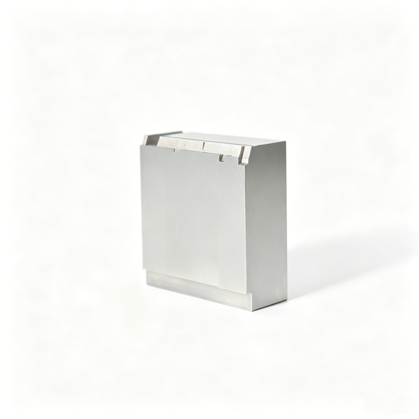
Drawing-Controlled Core and Cavity Insert
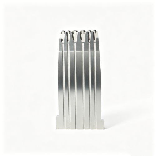
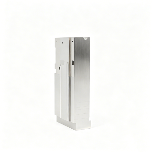
This rectangular insert is suited to RFQs where edge grooves, reference faces and working geometry must be interpreted from controlled design information. The distinct image from the same-company original product gallery 71792 is a visual reference only and is not another view of SKU009. It does not establish whether the grooves serve molding geometry, venting, clearance or location. Their function, dimensions and acceptance criteria must be confirmed by the approved customer drawing and engineering review.
Decide What the Grooves Mean
The most important RFQ question is whether each visible groove is functional geometry, a venting feature, a clearance relief, a locating detail or simply a non-functional boundary. Appearance cannot answer that question. A groove may be narrow enough to retain burrs, show taper, or require a controlled corner condition. Position relative to primary faces can matter more than general width, particularly where the insert mates with another component or where the groove begins and ends near a working edge. Mark each groove on the drawing and state its role, datum relationship and required edge condition.
Control the Primary Reference Faces
Before groove machining is planned, establish the faces that locate the insert in its assembly. The drawing should identify primary, secondary and tertiary datums, overall orientation, seating faces and any surface that must remain available for measurement. Groove spacing should be related to those references rather than only to an outside edge that may not be functional. If the insert is symmetrical, state whether symmetry is a requirement or merely a visual impression. If one face is intentionally left for later fitting, identify the allowance and the stage at which it will be reviewed. These decisions prevent a dimensionally plausible groove pattern from being wrongly positioned.
Conditional Machining Route
Once the reference scheme and groove purpose are approved, a conditional route may begin with reference-face preparation followed by cutting, grinding or EDM selected for the approved width, depth, corner and surface requirements. Cutting may be appropriate for accessible geometry, while grinding can support controlled finishing on suitable faces. EDM may be considered where access, narrow form or a specified edge condition makes it appropriate. The actual method depends on drawing requirements, feature scale, material specification and inspection access. Burr control should be included in the plan because narrow grooves may retain debris after machining, deburring or polishing.
Information Needed for the Drawing Package
A complete inquiry should include the latest drawing revision, a model when available, quantity, orientation view and marked groove callouts. Show groove width, depth, spacing, length, start and stop positions, corner radii, taper limits, edge breaks and the relationship to functional faces. Clarify whether groove bottoms require a surface condition, whether the feature may contain a blend, and whether any edge is a mating or shutoff edge. Indicate which faces are finished before groove work and which remain available for later fitting. The gallery image can accompany the package as orientation support, but it should never replace controlled dimensions or notes.
Inspection Strategy for Groove Geometry
Inspection should follow the drawing-defined function. Checks may include groove width, depth, spacing, length, corner condition and edge quality, together with position relative to primary faces where that relation is critical. Depending on the actual size and accessibility, suitable methods may include dimensional measurement, profile comparison, optical review, coordinate verification or an approved gauge. The support and datum setup should be recorded so that a narrow insert is not measured in an undefined condition. Visual review can address burrs, damage and transitions, but it should not substitute for a required positional or form check. No venting or molding result is inferred from appearance.
RFQ, Revision and Fit Decisions
For efficient review, identify SKU SUUXIANG-SAMPLE-008, attach the controlled drawing and model, and list every unresolved groove question. Ask the engineering team to confirm which faces locate the insert, which grooves are functional, whether any groove requires independent access, and how the part will be supported during inspection. If a revision changes groove spacing, depth, edge treatment or the relation to a seating face, record the impact on process selection and measurement. Quotation assumptions should be written beside the relevant feature, with customer approval required before they become production instructions. This keeps the RFQ technically useful without assigning an unsupported purpose.
Part-Specific FAQs
Can the grooves be called vents because they appear open?
No. Their purpose must be confirmed by the approved drawing and engineering review. They may instead represent molding geometry, clearance or location, and the photo cannot establish that distinction.
What groove details most affect the quotation?
Approved width, depth, spacing, corner condition, edge requirement, relation to primary faces and access direction are the main drivers. Narrow or enclosed features may change the conditional cutting, grinding or EDM route.
Submit the Groove-Controlled Drawing
Send the current revision and marked groove requirements for a focused review of this rectangular insert.
Reviews
There are no reviews yet.