
Deep-Cavity Mold Inserts, Reviewed Before Machining
Submit drawings for deep-cavity mold inserts for DFM, CNC, EDM, grinding, and inspection planning aligned with your critical dimensions.
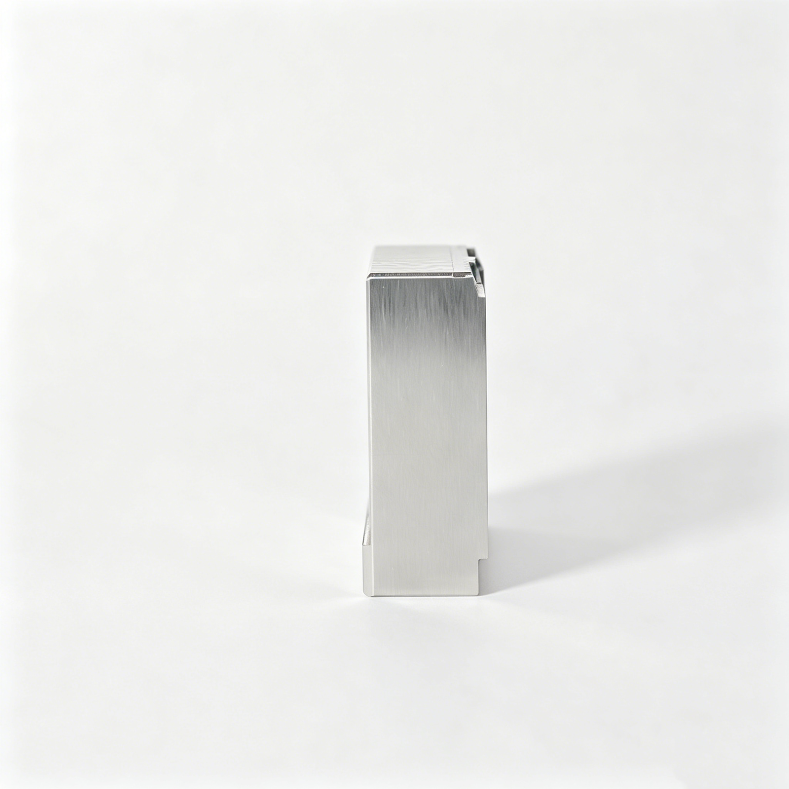
Representative Deep-Cavity Mold Insert Components







Related Configurable Component Families








Why Deep-Cavity Mold Inserts Need Process Planning
Deep-cavity mold inserts benefit from early decisions on access, EDM, grinding, inspection and controlled revisions.
Early DFM Review
Review cavity depth, corner geometry, datums and critical dimensions before quoting so the process route reflects functional priorities and manufacturing constraints.
Machining Access
Assess cutter reach, holder clearance and feature orientation early to identify areas better suited to CNC machining, EDM, or a revised insert split.
EDM Strategy
Plan electrode details, spark allowances and wire paths around ribs, corners and inaccessible geometry before machining begins, reducing avoidable rework.
Grinding Allowance
Define grinding stock and heat-treatment sequence with the drawing review, protecting final surfaces while leaving controlled material for finishing operations.
Inspection Planning
Align inspection methods to CTQ dimensions, datum references and reporting needs before release, making acceptance criteria visible throughout the project.
Revision Control
Keep drawing revisions, agreed requirements and delivery information visible, helping engineering, sourcing and quality teams maintain traceability as decisions change.
Drawing-Driven Component and Process Families
Assess configurable component families and process routes from your drawings, critical dimensions, materials, inspection requirements, and delivery priorities before production commitments are made.

CNC Machining Services
Precision CNC machining services for drawing-based custom parts requiring defined datums, material control, critical dimensions, and inspection planning. Process routes are reviewed against geometry, tolerance stack, surface requirements, quantity, and downstream assembly needs before quotation.
Upload a Drawing
CNC Milling
Custom CNC milling services for prismatic, contoured, and multi-feature components. Drawing review considers tool access, workholding, internal-corner limitations, machining allowance, datum transfer, and the appropriate sequence for heat treatment, EDM, grinding, or fitting.
Upload a Drawing
CNC Turning
Precision CNC turning services for shafts, sleeves, threaded features, concentric diameters, and rotational components. Evaluate diameter relationships, runout requirements, material condition, part holding, secondary milling needs, and inspection methods from the supplied drawing.
Upload a Drawing
5-Axis Machining
5-axis CNC machining supports complex surfaces, angled features, and multi-face components where fewer setups can improve datum consistency. Feasibility depends on tool reach, collision clearance, clamping strategy, material condition, critical dimensions, and required surface access.
Upload a Drawing
Swiss & Micro Machining
Swiss machining and micro machining address small-diameter, slender, and detail-intensive parts such as pins, miniature shafts, and connector features. Review feature scale, concentricity, burr control, material behavior, handling risk, measurement capability, and quantity requirements before routing.
Upload a Drawing
Wire & Sinker EDM
Wire EDM and sinker EDM services support precise profiles, narrow slots, hardened details, deep cavities, and inaccessible internal geometry. Electrode strategy, wire path, flushing, corner radii, recast-layer considerations, finishing allowance, and inspection requirements are assessed from the design.
Upload a Drawing
Precision Grinding
Precision surface and profile grinding supports controlled flatness, parallelism, profile accuracy, and fine finishing on suitable components. Grinding stock, heat-treatment distortion, datum strategy, wheel access, surface requirements, and measurement method should be established before release.
Upload a Drawing
Mold Core & Cavity Inserts
Precision mold core and cavity inserts are configured from part geometry, resin behavior, shutoff conditions, cooling interfaces, and mold-base relationships. Review cavity depth, steel selection, EDM and grinding needs, polish requirements, critical dimensions, and fitting responsibilities.
Upload a Drawing
Ejector & Ejection Components
Ejector pins, sleeves, and related ejection components are evaluated for fit, guidance, wear, venting, and removal force within the mold assembly. Drawings should clarify diameters, hardness requirements, working length, surface condition, mating components, and inspection priorities.
Upload a Drawing
Core Pins, Guide & Locating Components
Core pins, guide pins, and locating components are reviewed around alignment, concentricity, wear interfaces, assembly datums, and replacement fit. SUUXIANG assesses material, heat treatment, ground dimensions, mating tolerances, and application context before selecting a manufacturing route.
Upload a Drawing
Slides, Lifters, Gates & Mold Accessories
Mold slides, lifters, gates, and accessories are drawing-configured components requiring attention to travel, shutoffs, wear surfaces, cooling or ejection interfaces, and assembly relationships. Process planning considers machining access, EDM details, grinding stock, fitting, and inspection evidence.
Upload a Drawing
Connector Mold Components
Precision connector mold components support fine-pitch, multi-cavity, and mating-feature tooling requirements. Review pin and cavity geometry, datum relationships, small-feature manufacturability, material and heat-treatment requirements, EDM strategy, wear conditions, and verification methods before production.
Upload a Drawing
Stamping Die Components
Precision stamping die components are assessed from strip geometry, cutting conditions, material thickness, clearance, wear surfaces, and die-set interfaces. Suitable routes may combine CNC machining, wire EDM, grinding, heat treatment, fitting, and inspection according to drawing requirements.
Upload a Drawing
Injection, MIM, CIM & Overmolding Tooling
Injection, MIM, CIM, and overmolding tooling components are evaluated within verified production scope using part geometry, molding material, shrinkage assumptions, insert conditions, gating, venting, ejection, and assembly interfaces. Drawing review identifies manufacturability questions before commitments are made.
Upload a Drawing
Machining Materials
CNC machining materials are selected against function, machinability, hardness condition, corrosion environment, wear exposure, dimensional stability, and downstream treatment. Submit the specified grade, material standard, condition, traceability needs, and any approved substitution limits with the RFQ.
Upload a Drawing
Surface Finishes & Heat Treatment
Surface finishing and heat treatment requirements should be defined by functional surfaces, hardness targets, corrosion needs, friction, appearance, and dimensional risk. Review treatment sequence, masking, finishing allowance, post-treatment grinding, inspection criteria, and documentation expectations before release.
Upload a Drawing
Quality, Metrology & Documentation
Precision inspection, metrology, and quality documentation are planned around critical dimensions, datums, sampling expectations, measurement methods, revision status, and report requirements. Provide drawing callouts, acceptance criteria, material or treatment records needed, and any customer-specific documentation format.
Upload a Drawing
Prototyping & Low-Volume Production
Rapid prototyping and low-volume manufacturing support drawing revisions, design verification, bridge requirements, and controlled small-batch production. Feasibility is determined from material, process route, critical dimensions, finishing, inspection scope, quantity, and target delivery date rather than assumed capacity.
Upload a DrawingMaterials for Deep-Cavity Mold Inserts

Pre-Hardened Tool Steel
Often considered for moderate-duty cavity work where stable machining and a defined delivery condition matter. The selected grade, hardness condition, polishing requirement and critical dimensions should be reviewed against the drawing before release.

Hot-Work Tool Steel
A candidate for deep-cavity inserts exposed to elevated thermal cycling or demanding molding conditions. Machining access, EDM strategy, heat-treatment sequence and post-treatment grinding allowance require project-specific confirmation before commitment.

Corrosion-Resistant Tool Steel
Considered where resin chemistry, humidity or storage conditions may make corrosion resistance relevant. The final material choice should account for hardness, surface finish, cavity detail, heat treatment and the specified inspection plan.


Copper Alloy Inserts
An application-specific option for localized heat transfer where mold design permits its use. Material grade, strength, cooling interface, mating fit and machining approach must be verified with the mold design and operating requirements.
Deep-Cavity Mold Inserts: Machining, EDM and Grinding


Multi-Axis Milling
Multi-axis machining addresses angled features, contoured surfaces and accessible deep-cavity geometry with fewer setups where appropriate. The route is assessed against cutter reach, deflection risk, surface requirement and critical-dimension datum relationships.

Wire EDM Cutting
Wire EDM produces through-features, narrow slots and intricate profiles in conductive material when conventional tool access is limited. Wire path, start-hole location, datum transfer and finishing-pass requirements should be defined from the approved drawing.

Sinker EDM Forming
Sinker EDM forms deep, blind or sharp internal details that milling tools cannot reach reliably. Electrode strategy, spark allowance, corner condition and surface expectations are planned with the cavity geometry and subsequent fitting requirements.

Precision Grinding
Precision grinding brings selected datum faces, shutoff-related surfaces and functional dimensions toward their specified condition. Grinding stock, heat-treatment sequence, workholding and measurement method are reviewed to avoid compromising critical relationships.

Fitting And Inspection
Fitting and inspection verify functional interfaces, critical dimensions and documented requirements against the agreed plan. Measurement methods, reporting needs, revision status and any mating-component context are aligned before final release and delivery coordination.
Accessories for Deep-Cavity Mold Inserts

Locating Dowel Pins
Drawing-specified dowel pins establish repeatable insert position relative to the mold base or mating components. Review pin diameter, fit, datum relationship, service access, and replacement requirements alongside the deep-cavity insert design.

Guide Pins Bushings
Guide pins and bushings support controlled alignment during mold movement where the insert assembly requires guided engagement. Define mounting geometry, clearance, lubrication expectations, and potential interference with cavity access before machining.

Ejector Pin Sets
Ejector pins, sleeves, and related ejection components can be coordinated with cavity inserts when the drawing defines their interface. Critical checks include pin location, bearing length, clearance, surface condition, and ejection-side datum control.

Retaining Screw Sets
Retaining screws and fastening features secure removable inserts while allowing controlled service or revision. Provide thread standard, head style, seating geometry, torque considerations, and access direction so the fastening strategy can be reviewed.

Identification Markings
Part numbers, cavity identifiers, revision marks, and orientation references can be added when specified. Marking location and method should preserve functional surfaces, maintain traceability, and remain legible after planned finishing or assembly.
About SUUXIANG Deep-Cavity Mold Inserts
SUUXIANG is the sole public-facing brand of Dongguan SuuXiang Precision Mold Co., Ltd., established in 2010 in Chang’an Town, Dongguan, Guangdong, China. XiaoCheng Huang is the founder and legal representative. We support international engineering and sourcing teams with drawing-driven production of deep-cavity mold inserts, precision mold components, connector tooling, die components, and custom machined parts.
Our work combines CNC milling and turning, multi-axis machining, wire EDM, sinker EDM, precision grinding, fitting, and inspection. For deep-cavity mold inserts, project discussion begins with the drawing, 3D model, material, quantity, application, critical dimensions, surface requirements, datum strategy, and inspection expectations.
What differentiates SUUXIANG is disciplined process planning before production commitments. We examine machining access, electrode or wire path needs, grinding allowance, heat-treatment sequence, and revision control so the agreed manufacturing route and final documentation align with the verified inspection plan.

Core Capabilities for Deep-Cavity Mold Inserts
Critical-Dimension Drawing Review
SUUXIANG reviews deep-cavity mold insert drawings before quotation to identify critical dimensions, datum relationships, tolerance stacks, surface requirements, tool access, and heat-treatment sequencing. This early discussion helps align the proposed route with the part’s functional and inspection priorities.
- Confirm critical-to-quality dimensions and datum strategy
- Review wall geometry, reach limitations, and corner access
- Identify surface, material, and heat-treatment requirements
- Define drawing revisions before production planning

CNC and EDM Route Selection
Deep cavities often require a planned combination of CNC machining, sinker EDM, wire EDM, and intermediate finishing rather than a single process. SUUXIANG evaluates geometry, electrode access, wire paths, stock condition, and required surfaces to develop a drawing-led manufacturing route.
- Use CNC machining where cutting access is practical
- Assess electrode strategy for inaccessible cavity features
- Review wire-EDM paths for profiles and relief details
- Plan machining allowances between process stages

Grinding and Fitting Strategy
Grinding and fitting are considered alongside the machining route when deep-cavity mold inserts require controlled mating conditions or finished reference surfaces. The review considers grinding stock, distortion risk after heat treatment, assembly interfaces, and the dimensions that must remain protected through finishing.
- Reserve grinding stock on designated surfaces
- Sequence heat treatment and finishing around critical features
- Review mating faces, locating features, and fit conditions
- Protect functional datums during final processing

Fitting and Inspection
Inspection planning for deep-cavity mold inserts should reflect the drawing’s critical features and agreed reporting needs. SUUXIANG coordinates dimensional checks, documentation expectations, revision status, and delivery information so the final record corresponds to the confirmed order and inspection plan.
- Align inspection methods with critical dimensions
- Confirm reporting requirements before production release
- Maintain visible revision-control communication
- Match final documentation to the verified order

Questions to Ask When Comparing Deep-Cavity Mold Insert Suppliers
Compare documented drawing review, process planning, inspection alignment and revision visibility against a quote-only sourcing workflow.
← Swipe left or right to view →
Deep-Cavity Mold Inserts Production Workflow
A drawing-led path that aligns DFM, machining, EDM, grinding, inspection, and delivery requirements before production commitments are made.
RFQ and Drawing Review
We review 2D drawings, 3D models, material, quantity, application, critical dimensions, surface requirements, inspection needs, and requested delivery date.
DFM and Process Planning
The team evaluates datum strategy, tool access, tolerance stack, heat-treatment sequence, machining allowance, electrode needs, wire paths, and inspection approach.
CNC and EDM Manufacturing
Approved deep-cavity mold inserts proceed through the planned CNC machining, wire EDM, sinker EDM, and intermediate checks appropriate to the geometry.
Grinding and Precision Fitting
Grinding stock, mating interfaces, and functional fits are controlled through the specified finishing route, with revision information retained throughout the work.
Inspection and Delivery Coordination
Finished parts are checked against the agreed inspection plan, then packed with order-matched documentation and coordinated for shipment according to confirmed requirements.
How to Source Deep-Cavity Mold Inserts From SUUXIANG
A drawing-led workflow for reviewing manufacturability, confirming production details, and coordinating inspected delivery.
Submit Your Drawing Package
Provide 2D drawings, 3D models when available, material and heat-treatment requirements, quantity, critical dimensions, surface priorities, inspection needs, application context, and target delivery date.
Review DFM and Quotation
SUUXIANG reviews datum strategy, tool access, machining allowances, EDM or wire paths, grinding requirements, and revision details before confirming a process route and quotation.
Approve Production Details
Confirm the quoted scope, drawing revision, quality expectations, delivery requirements, and any sample or first-article review needs before production commitments are released.
Coordinate Inspection and Delivery
Production follows the agreed process plan, with inspection documentation aligned to the verified requirements and delivery coordination kept visible through final shipment preparation.
Deep-Cavity Mold Inserts: Certification and Quality Documentation Review
Deep-Cavity Mold Inserts: Customer Project Evidence
Approved customer testimonials and case outcomes for deep-cavity mold insert projects are published only after customer authorization and review of the supporting project records.
SUUXIANG does not present unverified delivery, tolerance, inspection, or performance outcomes as customer feedback. Relevant evidence is reviewed against the applicable drawing and inspection plan.
For a comparable project discussion, submit the drawing, material, critical dimensions, quantity, and inspection requirements so the appropriate machining, EDM, grinding, and documentation route can be evaluated.
Deep-Cavity Mold Inserts FAQ
Practical answers for reviewing drawings, process requirements, inspection evidence, revisions and delivery before production begins.
What is the minimum order quantity for deep-cavity mold inserts?
What files should I send for a deep-cavity mold insert quote?
Which materials can be considered for deep-cavity mold inserts?
How is lead time planned for deep-cavity mold inserts?
Can SUUXIANG support first-article or sample deep-cavity mold inserts?
What inspection reports can be supplied with mold inserts?
How are revisions and intellectual property handled for custom insert drawings?
Can deep-cavity mold inserts be shipped internationally?
The Complete Buyer’s Guide to deep-cavity mold inserts
Use this decision framework to specify deep-cavity mold inserts, compare machining and material options, evaluate supplier controls, and avoid DFM, tolerance, cooling, and verification mistakes that delay tooling programs.
1. What Are deep-cavity mold inserts?
Two functional layers distinguish a deep-cavity mold insert: the removable precision component forms recessed or tool-inaccessible geometry, while the surrounding core or cavity block provides structural support and location. It is part of the mold tooling, not a metal or plastic item placed in the cavity and encapsulated by the molded product.
One insert is also not a complete mold base. A base carries plates, guidance, clamping interfaces and other mold architecture; an insert is a controlled working surface selected where machining access, EDM electrode reach, wire path, polishing access, venting or local cooling would be compromised in one solid block.
At drawing review, the buyer should ask whether replacement, maintenance and revision risk justify a separable interface. The answer depends on datum control, sealing faces, retention, thermal path, insert-line acceptability and inspection access—not depth alone.
2. Evolution of Deep-Cavity Tooling
Two process families—CNC cutting and EDM—made it practical to separate difficult cavity geometry from a large mold block. Instead of reworking or scrapping an entire block after a change or localized wear event, toolmakers could replace a defined insert while retaining the surrounding mold structure; CNC and EDM remain common routes for core and cavity inserts (https://www.youtube.com/watch?v=o3Hb1mUO_d4).
Three design drivers accelerated modular tooling: deeper features that restrict cutter access, wear zones needing service, and product revisions concentrated in a small area. A replaceable insert can also make polishing, venting, cooling access, and controlled fitting more manageable, provided its datum faces, retention, sealing surfaces, and stack-up are designed as a system.
One process route does not fit every deep cavity. CNC is generally favored where tool access, rigidity, and corner radii permit efficient cutting; sinker EDM or wire EDM becomes relevant for inaccessible details, sharp internal geometry, or required profiles in conductive material. SUUXIANG should review geometry, material and heat-treatment sequence, electrode strategy, grinding stock, and inspection datums before selecting the route.
3. Types of deep-cavity mold inserts
Deep-cavity configuration follows the molded feature, mold half, and service strategy. Specify the insert boundary early so tool access, shutoff sealing, polishing, and replacement can be reviewed together.
| Configuration | Typical Use | Key Constraint |
|---|---|---|
| Block | Deep rectangular cavity | Polishing access |
| Round | Boss or bore | Concentric location |
| Rib or blade | Thin deep rib | Tip support |
| Split | Undercut detail | Shutoff mismatch |
| Vented | Air-trap endpoint | Cleaning access |
Core-Side And Cavity-Side
Core-side inserts form internal plastic features on the moving half; cavity-side inserts define exterior surfaces on the fixed half.
For either, locate sealing lands on stable datum faces and keep fastener access clear of the deep feature.
Block, Round, And Rib
Block inserts suit rectangular pockets and connector-housing arrays; round inserts suit bores, bosses, and concentric details.
Rib or blade inserts reach narrow ribs, but thin tips require EDM access and a supported shutoff.
Split, Detail, And Venting
Split inserts divide inaccessible geometry; interchangeable detail inserts isolate revisions, logos, or wear features.
Venting-oriented inserts serve trapped-air endpoints. Define cleaning access, sealing interfaces, and replacement criteria before release.
4. Materials for deep-cavity mold inserts
P20, H13, S136, and PM grades solve different cavity risks; a grade name alone is not a material specification. Match steel selection to resin chemistry, filler load, finish, cycle-life target, and planned repair route.
| Material Family | Primary Strength | Typical Risk | Resin Environment |
|---|---|---|---|
| Pre-hardened steel | Fast machining | Lower abrasive wear | Unfilled, moderate volume |
| Hot-work steel | Tough thermal cycling | Post-hardening distortion | General engineering resins |
| Stainless steel | Corrosion, polish | Higher material cost | PVC, FR, humid processing |
| PM tool steel | Abrasive wear | Finishing cost | Glass- or mineral-filled |
| Copper alloy | Fast heat transfer | Low wear resistance | Localized cooling zones |
| Porous venting material | Gas release | Clogging or damage | Deep trapped-air areas |
Read The Material Tradeoffs
P20-type pre-hardened steel shortens initial processing and suits moderate-volume, non-corrosive resin work. Its lower hardness can limit wear life with glass-filled compounds.
H13-type hot-work steel offers toughness and heat-check resistance after a controlled hardening sequence. It is often considered where thermal cycling and deep-section stress matter.
Specify For Resin And Finish
S136-type stainless grades improve corrosion resistance for PVC, flame-retardant, or moisture-sensitive environments, while supporting polished cosmetic surfaces. Heat treatment, polish sequence, and weld-repair expectations must be agreed before release.
PM tool steels raise wear resistance for abrasive filled resins but can increase material and finishing cost. Define the filler, expected shots, surface class, and approved repair method on the drawing.
Use Specialty Materials Carefully
Copper alloys remove heat faster than tool steel but sacrifice strength and wear resistance, so they are commonly localized rather than used for entire cavity faces. Porous venting materials require protected placement because resin can foul open structure.
EDM, grinding, and fitting allowances must follow the selected material and heat-treatment state. SUUXIANG should review the material callout with the drawing, resin, and inspection priorities before manufacture.
5. Machining and finish options
A deep cavity is normally roughed by CNC milling before finish milling, EDM, grinding, and inspection establish functional geometry. Process selection should follow the drawing’s datum scheme, access limits, surface callouts, and cosmetic priority.
| Feature Or Requirement | Preferred Process | Key Planning Point |
|---|---|---|
| Deep narrow ribs | Sinker EDM | Electrode access and wear |
| Sharp internal corners | Sinker EDM | Corner geometry versus electrode radius |
| Fine connector details | Micro-machining and EDM | Datum control between operations |
| High-polish surfaces | Finish milling and polishing | Protect surface after polishing |
| Logo or date codes | Laser marking or replaceable insert | Lock location to drawing datum |
Select The Feature Route
CNC milling removes bulk stock efficiently; long-reach finishing is limited by tool deflection and access. Sinker EDM forms inaccessible ribs and sharp internal corners, while wire EDM separates profiles or slots.
Fine connector details may require micro-machining, EDM, and grinding in one controlled sequence. Drilling establishes cooling, vent, or locating features only where the specified geometry permits.
Match Finish To Function
Polishing should be specified by the required surface condition and part appearance, not as a generic ‘mirror’ request. Texturing, coating, and laser marking must be located against datums so later fitting does not disturb them.
Replaceable logo or date-code areas are commonly designed as small inserts. That approach confines future identification changes to a defined component rather than the full cavity.
Plan EDM And Verification
EDM electrodes need documented geometry, clearance, wear assumptions, and finishing passes before machining begins. Recast-layer management may require subsequent polishing or other approved finishing where surface integrity is critical.
Inspection should confirm cavity depth, rib width, corner condition, datum relationships, finish acceptance, and marking location against the released revision. Higher cosmetic requirements usually add electrode, polishing, protection, and inspection time.
6. Deep-cavity mold inserts: quality elements
Deep-cavity reliability is established at the interfaces, not by cavity depth alone. A drawing review should convert sealing, alignment, thermal, venting, hardness, and inspection needs into measurable acceptance criteria before machining.
Datums And Mating Faces
Three defined datums should control pocket location, insert seating, and shutoff geometry. Continuous, clean mating faces and specified bearing length reduce flash, resin leakage, mismatch lines, and time-consuming bench fitting.
Corners, Vents, And Cooling
0.2 mm is a common minimum vent-depth reference for many mold designs, but resin and process conditions must govern the released value. Corner radii, accessible vent paths, and cooling distance require joint review to prevent burn marks, trapped gas, cracking, and uneven cooling.
Heat Treatment And Records
100% of identified critical dimensions should be inspected against the released revision after relevant heat treatment, grinding, or fitting. Hardness verification, distortion checks, surface-roughness results, datum-based measurement records, and revision traceability help prevent premature wear and difficult maintenance.
7. How to choose a manufacturer
Two documents should anchor supplier selection: the controlled 2D drawing and matching 3D model. Request a written DFM response that identifies datums, tool access, EDM electrodes or wire paths, grinding stock, and unresolved critical dimensions.
| Request | Evidence | Decision Value |
|---|---|---|
| Measurement plan | Datums and method | Tests tight tolerances |
| Inspection report | Actual CTQ results | Supports acceptance |
| Heat-treatment record | Required condition | Maintains traceability |
Verify Process Route
One quotation should name the planned CNC, sinker EDM, wire EDM, grinding, fitting, and inspection sequence.
Two questions reveal depth: Which feature requires an electrode, and how will the supplier protect connector contact geometry and shutoff surfaces?
Control Material And Approval
One material record should link the purchased steel to the ordered insert and its revision.
Two approval gates are useful: review the first inspected sample against agreed CTQs, then authorize any correction through documented revision control.
Manage Cross-Border Delivery
One project owner should issue a defined update cadence covering DFM decisions, machining status, inspection results, and shipment readiness.
Two ownership questions matter: Who retains programs and electrodes, and what spare-insert strategy supports future connector-tooling changes?
8. Common deep-cavity insert mistakes
One DFM review before purchase-order release should convert deep-cavity risks into agreed geometry, process route, and inspection criteria. For deep-cavity mold inserts, assumptions that remain only in CAD commonly become rework, unstable molding, or disputed acceptance.
Feature Access And Corners
A deep feature treated as ordinary milling can force excessive tool stick-out, chatter, poor floor finish, or an EDM redesign. During DFM, confirm cutter reach, wire path, electrode split lines, and relief geometry.
Zero-radius internal corners demand EDM or leave unmachined material; omitted draft can obstruct release or polishing. Specify functional radii, draft, and relief only where the molded part permits them.
Steel And Thermal Control
Resin, fillers, corrosion exposure, and expected wear determine whether a steel and heat-treatment route is suitable; selecting by hardness alone can shorten service life. During DFM, provide resin grade, additives, production expectation, and surface requirements.
Insufficient venting or cooling near a deep cavity can cause air traps, burn marks, uneven shrinkage, and long cycles. Review vent locations, cooling access, sealing faces, and serviceability before release.
Datums, Seams, And Tolerances
Tolerances applied uniformly to every feature increase grinding, EDM, inspection, and cost without improving the molded function. During DFM, identify critical dimensions, allowable stack-up, measurement method, and process-relevant tolerances.
Insert seams can print witness lines or leak flash, while unclear datums produce inconsistent inspection results. Define seam acceptability, sealing interfaces, primary-secondary-tertiary datums, and revision-controlled 2D and 3D files.
9. From drawing to validated insert
One controlled launch plan converts a drawing into an auditable insert, rather than a sequence of assumptions. For deep-cavity mold inserts, define acceptance evidence before cutting material.
RFQ Package And Alignment
One released RFQ package should include 2D drawings, 3D models, revision level, quantity, material and heat-treatment requirements, critical dimensions, surface requirements, mating context, target date, and required reports.
Two parties should align quotation scope against the drawing: supplied stock, machining route, EDM, grinding, fitting, inspection, packaging, and excluded tryout work.
Review And Process Gates
Three decision gates reduce avoidable rework: DFM approval, material confirmation, and first-article acceptance. Each gate should record datum strategy, tool access, electrode or wire path, grinding stock, heat-treatment sequence, and measurement method.
One revision register should identify the file owner, revision date, affected features, approval status, and disposition of prior work. Do not release machining from an uncontrolled model.
Build, Validation, And Handoff
A confirmed route may combine CNC machining, heat treatment, EDM, grinding, finishing, fitting, and dimensional inspection according to the approved plan. Inspection results should reference the controlled drawing and identified datums.
Prototype programs may prioritize functional tryout feedback; low-volume work needs repeatable inspection records; production-intent work should additionally define maintenance documentation, spare-insert needs, shipment acceptance, and change-control responsibilities.
10. Pricing deep-cavity mold inserts
Nine quotation inputs determine the route: insert envelope and steel grade, cavity depth, CNC removal time, EDM burn time, electrode count, heat treatment, finish, tolerance, inspection, quantity, and requested delivery date.
Two controlled files make supplier quotations comparable: the revision-identified 2D drawing with datums and CTQs, plus the 3D model showing cavity access, radii, shutoffs, and mating interfaces. A low initial price can shift risk downstream when it excludes electrodes, post-heat-treatment grinding stock, inspection reporting, or revision-controlled rework.
| Cost driver | Quotation effect | Evidence to provide |
|---|---|---|
| Size and material | Stock cost and machining time | Finished envelope; specified grade |
| Depth, CNC, and EDM | Tool reach, burn time, electrodes | Depth map; corner radii; access |
| Heat treatment and finish | Sequence, distortion allowance, polishing | Hardness; finish callouts |
| Tolerance and inspection | Grinding, measurement, report scope | Datums; CTQs; report requirement |
| Quantity and lead time | Setup allocation and scheduling | Order quantity; required receipt date |
Submit Deep-Cavity Mold Inserts Drawings for DFM Review
Upload 2D drawings and 3D models with material, quantity, critical quality priorities, inspection needs, and target delivery date for focused quotation review.