
Micro-Feature Mold Inserts: Drawing-to-Inspection Manufacturing
Send your drawing for DFM-led micro-feature mold inserts manufacturing with critical-dimension review, coordinated machining, EDM, grinding, and inspection.
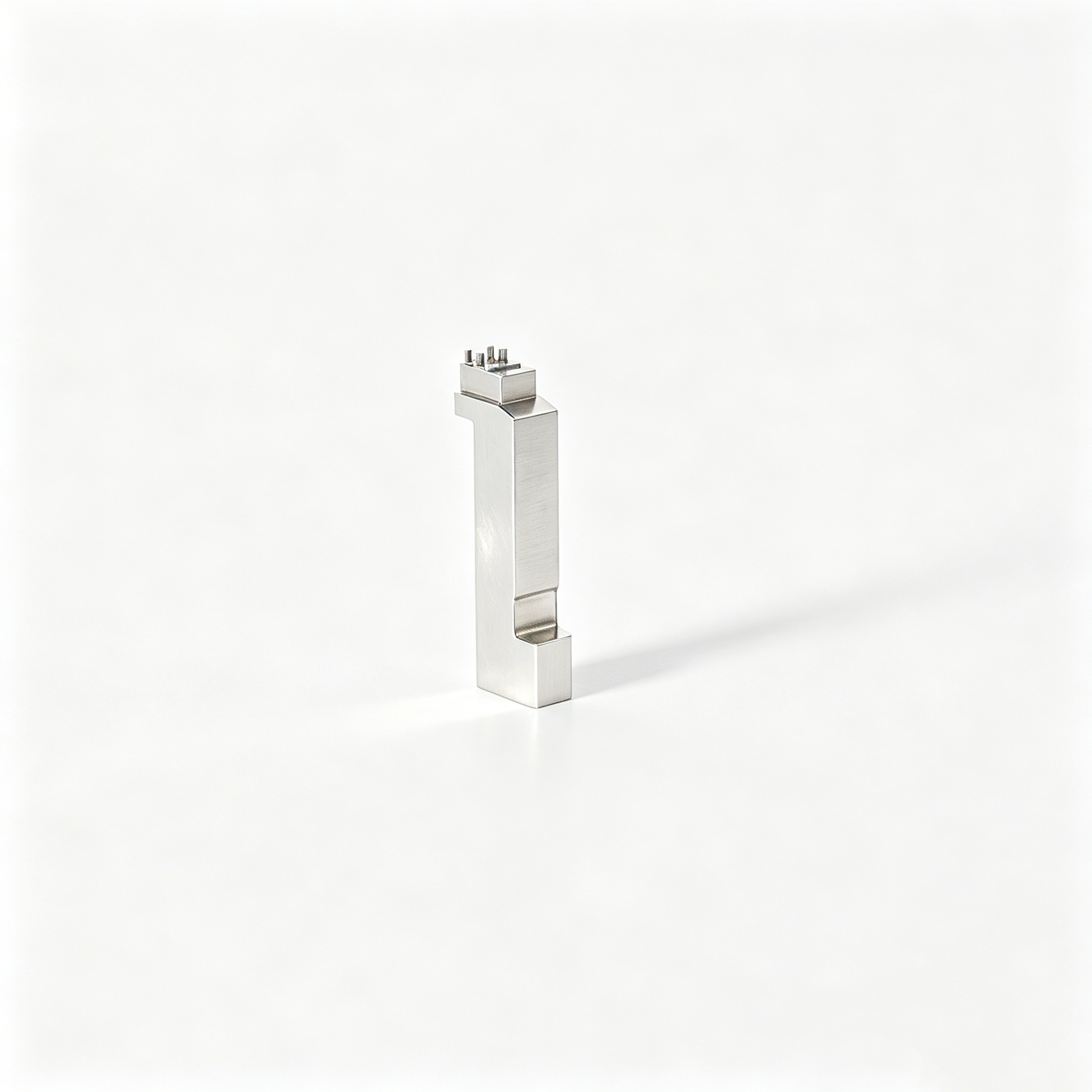
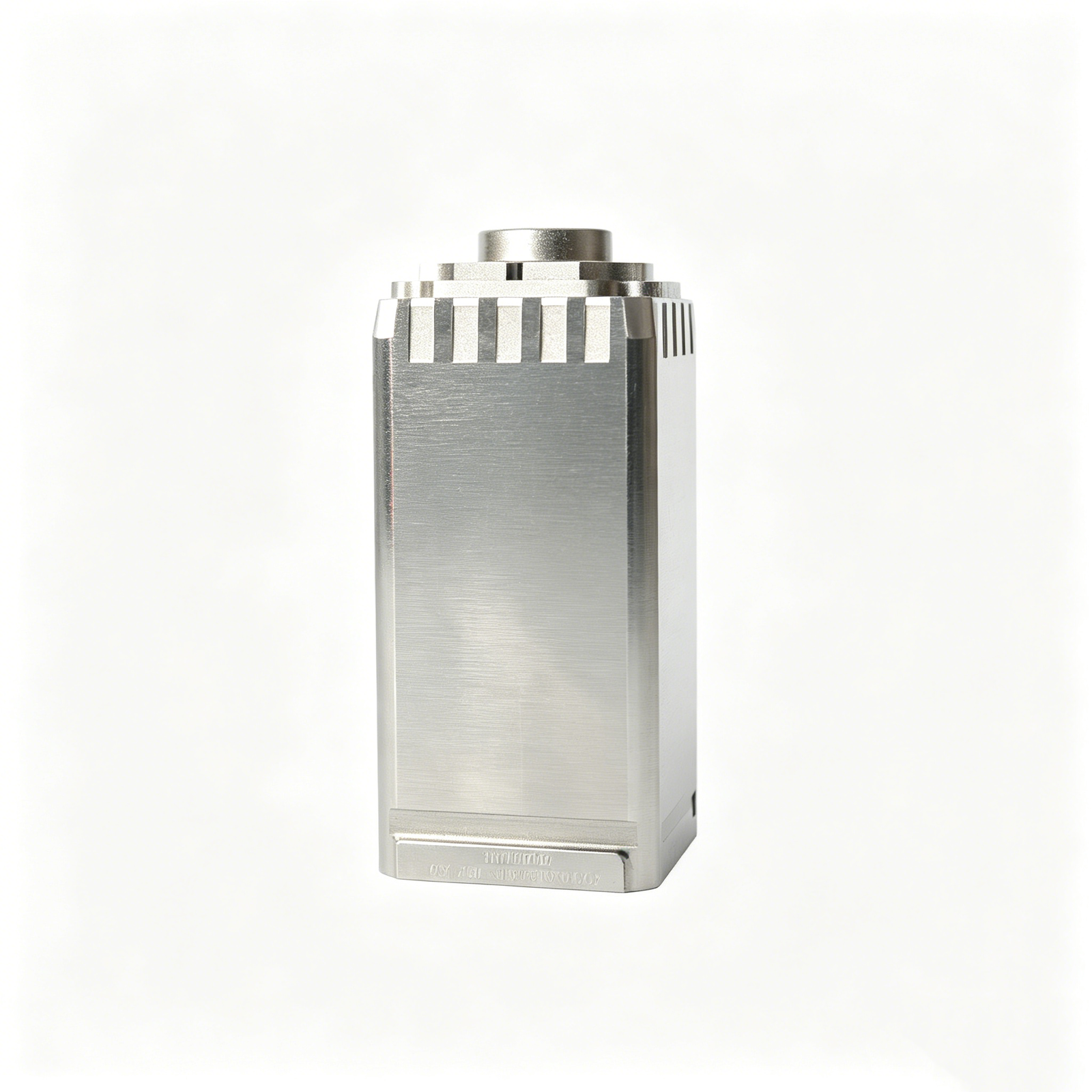
Representative Micro-Feature Mold Insert Components



Related Configurable Component Families and RFQ








Engineering Advantages for Micro-Feature Mold Inserts
Structured planning from drawing review through inspection documentation for precision insert projects.
Drawing Comprehension
We review 2D drawings and 3D models to identify functional geometry, interfaces, material requirements, and manufacturability questions before quotation.
Critical Dimension Planning
Critical dimensions, datums, tolerance relationships, and surface priorities are discussed early so process planning follows the part’s functional requirements.
Coordinated Process Routes
CNC machining, EDM, precision grinding, and fitting are sequenced around tool access, electrode strategy, wire paths, and machining allowances.
Inspection Planning
Inspection methods are aligned with critical features, datum strategy, reporting needs, and the verified plan required for the specific order.
Revision Visibility
Drawing revisions, technical decisions, and delivery information remain visible throughout the project to support controlled communication and traceable execution.
RFQ-Ready Communication
Send drawings, material, quantity, quality expectations, and delivery targets so SUUXIANG can prepare a focused technical discussion for micro-feature mold inserts.
Precision Mold Components and Machining Services
Drawing-driven component families and process routes for critical features, controlled revisions, and inspection-ready production.

CNC Machining Services
Precision CNC machining services for drawing-based parts requiring planned tool access, datum control, material verification, and defined inspection methods. Process selection is reviewed against critical dimensions, surface requirements, geometry, quantity, and delivery priorities before production commitments are made.
Upload a Drawing
CNC Milling
Custom CNC milling services for prismatic components, pockets, ribs, plates, inserts, and complex machined features. Drawing review considers cutter reach, corner radii, workholding, machining allowance, datum sequence, and whether subsequent EDM or grinding is needed.
Upload a Drawing
CNC Turning
Precision CNC turning services for shafts, sleeves, pins, bushings, and rotational features. Part review addresses concentricity, runout, shoulder geometry, thread requirements, material condition, clamping strategy, and the inspection approach for critical diameters and lengths.
Upload a Drawing
5-Axis Machining
5-axis CNC machining supports contoured surfaces, angled features, deep-access geometries, and multi-face work where reduced setups can protect datum relationships. Feasibility depends on machine access, workholding, tool length, material behavior, required finish, and inspection strategy.
Upload a Drawing
Swiss & Micro Machining
Swiss machining and micro machining support small, slender, and detailed components where concentricity, feature access, and handling require close process control. Drawings should define critical dimensions, burr limits, surface requirements, material condition, and applicable measurement methods.
Upload a Drawing
Wire EDM Services & Sinker EDM Services
Wire EDM services and sinker EDM services address hardened materials, sharp internal geometry, fine slots, deep ribs, and features inaccessible to conventional cutters. Process planning evaluates wire path or electrode strategy, flushing, EDM allowance, recast-layer considerations, and subsequent finishing needs.
Upload a Drawing
Precision Grinding
Precision surface and profile grinding supports flatness, parallelism, profile accuracy, controlled stock removal, and fine surface requirements. Grinding plans account for heat-treatment sequence, grinding stock, datum protection, part stability, wheel access, and the specified inspection method.
Upload a Drawing
Mold Core & Cavity Inserts
Precision mold core and cavity inserts are configured from approved drawings and molding requirements. Review focuses on shutoff geometry, cooling and venting interfaces, gate location, material and heat treatment, machining or EDM route, critical dimensions, and fitting relationships.
Upload a Drawing
Ejector & Ejection Components
Ejector pins, sleeves, and ejection components are produced to suit the mold’s guidance, clearance, travel, and wear requirements. Engineering review considers mating features, material condition, hardness, surface finish, head geometry, lubrication needs, and replacement interchangeability.
Upload a Drawing
Core Pins, Guide & Locating Components
Core pins, guide pins, and locating components establish feature position and repeatable mold alignment. Drawings should clarify datum relationships, fit classes, engagement length, wear surfaces, material and heat-treatment requirements, and the inspection points needed to verify mating performance.
Upload a Drawing
Slides, Lifters, Gates & Mold Accessories
Mold slides, lifters, gates, and accessories are configurable components for motion, release, material flow, and supporting mold functions. Planning addresses travel paths, interference risk, shutoff faces, angle relationships, wear control, machining access, fitting requirements, and assembly interfaces.
Upload a Drawing
Connector Mold Components
Precision connector mold components support high-density contact layouts, small pitch features, insert relationships, and repeatable molding interfaces. Manufacturing review emphasizes datum strategy, fine-feature EDM or grinding needs, material stability, burr control, mating geometry, and inspection accessibility.
Upload a Drawing
Stamping Die Components
Precision stamping die components include punches, dies, guide elements, forming details, and related custom parts built from drawings. Process planning considers strip direction, cutting or forming edges, clearance, material and heat treatment, grinding sequence, EDM requirements, and fitting relationships.
Upload a Drawing
Injection Mold Components, MIM, CIM & Overmolding Tooling
Injection, MIM, CIM, and overmolding tooling components are evaluated within verified production scope. The drawing review considers material flow interfaces, shrinkage-related requirements, gates, vents, parting lines, inserts, thermal sequence, and the machining, EDM, grinding, and fitting route.
Upload a Drawing
Machining Materials
CNC machining materials are selected against mechanical function, dimensional stability, corrosion resistance, wear, thermal treatment, and machinability. Provide the specified grade, condition, substitutions policy, and any material documentation requirement so the process route can be assessed correctly.
Upload a Drawing
Surface Finishes & Heat Treatment
Surface finishing and heat treatment are specified according to functional surfaces, wear, corrosion, release, appearance, and dimensional risk. Review should define finish areas, roughness expectations, coating or treatment type, masking needs, hardness requirements, and post-treatment grinding allowance.
Upload a Drawing
Quality, Metrology & Documentation
Precision inspection, metrology, and quality documentation are planned around critical-to-quality dimensions, datums, tolerances, and the order’s reporting requirements. Align drawing revisions, sampling expectations, measurement methods, material records, and final documentation before production begins.
Upload a Drawing
Prototyping & Low-Volume Production
Rapid prototyping and low-volume manufacturing support design validation, tool trials, revisions, and controlled bridge quantities. A useful RFQ includes drawings or models, material, quantity, critical features, quality requirements, target date, and application context affecting manufacturability.
Upload a DrawingMaterials for Micro-Feature Mold Inserts

Tool Steel
A common choice for mold cores, cavities, and inserts requiring a balanced route through machining, EDM, grinding, and heat treatment. Grade, hardness target, corrosion exposure, and dimensional priorities should be confirmed before production.

Stainless Steel
Used where corrosion resistance, clean processing environments, or application-specific material requirements influence insert selection. Machining behavior, heat-treatment condition, surface finish, and inspection datums require review against the approved drawing and mating conditions.

Pre-Hardened Steel
Suitable for components that may benefit from machining in a supplied hardened condition and reduced post-machining heat-treatment change. The drawing review should establish wear demand, finish requirements, grinding stock, and critical-dimension inspection methods.

Powder Metallurgy Steel
Considered for demanding wear environments or complex insert geometries when the specified grade and process route are supported by project evidence. Electrode strategy, EDM finish, heat treatment, and final inspection planning remain drawing-dependent.

Copper Alloys
Applied selectively for inserts or features where thermal behavior is a design consideration. Alloy selection must be checked against strength, wear, joining, machining access, surface requirements, and the application-specific drawing before a production commitment.
Micro-Feature Mold Inserts: Supported Processes

CNC Milling
CNC milling develops insert profiles, pockets, parting features, and accessible detail from the approved model. Tool access, remaining stock, and datum sequence are reviewed to create a controlled route for subsequent EDM or grinding.


Micro Machining
Micro machining addresses fine ribs, small pockets, miniature pins, and other compact details within verified project scope. Cutter reach, feature rigidity, burr risk, and inspection access are assessed early so the drawing can guide a realistic process plan.

Wire EDM
Wire EDM produces through profiles, narrow slots, and hardened-material details where a controlled wire path is appropriate. The team reviews start-hole access, cut sequence, corner requirements, and allowance to protect functional geometry and mating relationships.

Sinker EDM
Sinker EDM forms deep cavities, sharp internal details, and geometry beyond practical milling access using planned electrodes. Electrode strategy, flushing conditions, finish needs, and any follow-up grinding or fitting requirements are aligned with the drawing.

Grinding And Inspection
Precision grinding, fitting, and inspection complete applicable micro-feature mold inserts through controlled stock removal, mating checks, and drawing-based measurement. Inspection methods and report requirements are agreed against critical dimensions, datums, revision level, and order expectations.
Micro-Feature Mold Inserts: Supported Accessories and Added Features


Locating Elements
Locating pins, keys, and reference features help establish controlled insert orientation during assembly and service. SUUXIANG reviews mating geometry, tolerance stack, retention method, and inspection points before committing to a process route.

Ejection Parts
Ejector pins, sleeves, and related ejection components can be evaluated alongside cavity and core geometry. The review considers clearance, travel, bearing surfaces, material requirements, grinding needs, and risks to delicate molded features.

Slides and Lifters
Slides and lifters support undercuts, release motion, and localized feature formation where the design requires them. A drawing-based review clarifies motion direction, contact surfaces, tool access, fitting requirements, and maintenance-sensitive areas.

Gate Features
Gate-related inserts and localized flow features can be incorporated when the molding design defines their function. Review focuses on insert boundaries, EDM or machining access, surface requirements, and interfaces that affect fit and revision control.

Connector Tooling
Connector-tooling elements can be configured for precision cavities, cores, terminals, and locating details. SUUXIANG evaluates critical dimensions, datum relationships, micro-feature access, electrode strategy, grinding stock, and the required inspection documentation.
About SUUXIANG Precision Manufacturing
SUUXIANG is the sole public-facing brand of Dongguan SuuXiang Precision Mold Co., Ltd. Founded in 2010 by XiaoCheng Huang, its founder and legal representative, the company is based on the 2nd Floor of Sanhe Industrial Park in Chang’an Town, Dongguan City, Guangdong, China. We help global engineering, sourcing, and quality teams translate drawings and specifications into inspected precision mold components, custom machined parts, connector tooling, and micro-feature mold inserts.
Our work is drawing-driven. Before quotation or production commitments, we review critical dimensions, datums, tolerance stacks, material and heat-treatment requirements, surface priorities, machining access, and inspection needs. Process planning can combine CNC milling and turning, multi-axis machining, EDM, precision grinding, fitting, and inspection according to verified project requirements.
What distinguishes SUUXIANG is disciplined coordination from DFM through final documentation. We keep revision control, manufacturing decisions, inspection methods, and delivery information visible, so buyers can evaluate technical risk before production begins. Submit an RFQ with your drawing, quantity, quality requirements, and target delivery date for a focused technical review.

Micro-Feature Mold Inserts: From DFM to Inspection
DFM and Datum Review
Before quotation, SUUXIANG reviews the drawing, model, critical dimensions, datum scheme, surface requirements and mating context. This establishes a practical manufacturing route for micro-feature mold inserts and identifies questions that should be resolved before production commitments.
- Identify critical-to-quality dimensions and functional datums
- Check tool access, wall conditions and feature relationships
- Confirm material, heat-treatment and surface requirements
- Record revision status and open technical questions

CNC and EDM Strategy
Fine cavities, ribs, slots and internal corners may require a planned combination of CNC machining, wire EDM and sinker EDM. The route should be selected around geometry, access, finish requirements and inspection points rather than assumed from feature size alone.
- Assess machining access before selecting the process route
- Plan electrode details and EDM reference surfaces
- Define wire paths for narrow or enclosed features
- Protect critical datum relationships between operations

Grinding and Fitting Allowance
Grinding stock and fitting requirements need definition early when surfaces control shutoff, guidance, location or assembly behavior. SUUXIANG coordinates allowance between machining stages so finishing work supports the drawing intent without removing material needed for final correction.
- Assign grinding allowance to relevant surfaces
- Separate functional fitting surfaces from cosmetic finishes
- Sequence heat treatment and finishing around dimensional risk
- Clarify mating-part conditions before final fitting

Inspection and Revision Control
Inspection planning should follow the approved drawing and identified critical features. SUUXIANG aligns measurement methods, reporting needs and revision records with the order, helping project teams verify micro-feature mold inserts against the evidence required for acceptance.
- Link inspection points to datums and critical dimensions
- Confirm required reports before production begins
- Maintain visible drawing and revision references
- Flag deviations or clarification needs for disposition

Why Choose SUUXIANG for Micro-Feature Mold Inserts
Compare an engineering-led drawing-to-inspection workflow with a typical generic sourcing path.
← Swipe left or right to view →
Micro-Feature Mold Inserts: Drawing to Delivery
A drawing-led sequence that keeps critical dimensions, process decisions, inspection requirements, and revision status visible before shipment.
Review Drawings and Requirements
We review 2D drawings, available 3D models, material, quantity, application context, critical dimensions, surface requirements, delivery target, and inspection documentation needs.
Plan DFM and Process
The team confirms datum strategy, machining access, tolerance stack, heat-treatment sequence, EDM or wire path needs, grinding stock, and inspection approach before commitment.
Machine Critical Insert Features
Approved work moves through the suitable CNC milling, turning, multi-axis machining, micro machining, wire EDM, sinker EDM, and precision grinding sequence.
Fit and Control Revisions
Components are fitted as required, while project communication tracks approved revisions, critical interfaces, dimensional priorities, and any drawing-controlled changes affecting manufacture.
Inspect Pack and Coordinate
Final inspection follows the agreed plan. We prepare order-matched documentation, protect finished components for packing, and coordinate shipment details with the customer.
How to Source Micro-Feature Mold Inserts
A controlled path from technical files and DFM review through production updates, inspection planning, and delivery coordination.
Submit Your Technical Package
Provide 2D drawings, 3D models when available, material and heat-treatment requirements, quantity, critical dimensions, inspection needs, application context, and target delivery date.
Align on DFM and Quote
Review datums, tolerance stack, machining access, EDM or grinding requirements, surface priorities, and revision status before SUUXIANG confirms the proposed process route and quotation.
Confirm Production Details
Approve the agreed drawing revision, quality expectations, sample or production scope, and delivery requirements so manufacturing planning reflects the current project specification.
Follow Manufacturing and Inspection
Receive coordinated communication on manufacturing progress, revision control, inspection planning, and final order documentation matched to the verified requirements for your micro-feature mold inserts.
Quality Documentation for Micro-Feature Mold Inserts
Customer Project Feedback and Outcomes
Customer project feedback will be published only after the outcome, supporting records, and permission to identify the customer have been verified.
Verified testimonials for micro-feature mold inserts must reflect the approved drawing revision, inspection scope, delivery outcome, and the customer’s authorized wording.
SUUXIANG does not publish anonymized performance figures or customer endorsements without traceable project evidence and written approval to share them.
Micro-Feature Mold Inserts FAQ
Practical RFQ, DFM, inspection, revision, and delivery guidance for drawing-based insert projects.
What information should I send for a micro-feature mold insert RFQ?
Can SUUXIANG review micro-feature mold inserts before quoting?
Which material and heat-treatment details matter for micro-feature mold inserts?
How do you control critical dimensions on small insert features?
What inspection reports are available for micro-feature mold inserts?
How are drawing revisions handled after an order is placed?
How should I plan lead time for micro-feature mold inserts?
How does SUUXIANG protect drawing confidentiality and project IP?
The Complete Buyer’s Guide to micro-feature mold inserts
A practical framework for defining micro-scale requirements, evaluating tooling and inspection competence, comparing material and insert options, and avoiding sourcing mistakes that drive variation, delays, and rework.
1. What Are micro-feature mold inserts?
Sub-millimeter features commonly define the micro-molding context, but micro-feature mold inserts are the tooling elements that create those features in a cavity, core, or dedicated insert pocket. They may be replaceable for maintenance or integrated into a larger mold component, and can form pins, ribs, apertures, channels, textures, shutoffs, or optical surfaces.
Two distinct objects are involved: the insert is the precision tool; the molded part is the polymer component it shapes. This is also different from insert molding, where a separate metal, ceramic, or other component is placed in the mold and becomes enclosed by the molded polymer.
Connector interfaces, microfluidic channels, micro-optical features, sensor housings, and miniature mechanisms illustrate the range of applications. Before selecting a process route, define the geometry the insert must reliably reproduce across cycles: critical dimensions, datum relationships, surface function, release behavior, and mating-component effects.
2. How micro-feature mold inserts Evolved
As feature scale decreases, dedicated micro-feature mold inserts can separate sensitive forming surfaces from the main tool, making replacement, finishing, and process-specific manufacture more manageable.
Wire EDM, sinker EDM, precision grinding, and other specialized routes address different geometries and surface functions. Select the route from feature form, datum access, material condition, draft, allowable recast layer, and required surface quality—not from a generic process preference.
Miniaturized electronics, diagnostics, and optical products can make cavity-to-cavity consistency, alignment, handling, and inspection evidence critical sourcing concerns. Define the critical features and measurement method before steel is cut.
3. Types of micro-feature mold inserts
Micro-feature mold inserts are best classified by what they form, protect, or locate. The category determines the split line, retention method, inspection datum, and replacement plan that should appear on the drawing.
| Insert Type | Suitable Geometry | Mounting Concern | Drawing Input |
|---|---|---|---|
| Core or cavity | Pins, ribs, shutoffs | Datum and retention | Critical dimensions |
| Wear insert | Gates, contact zones | Replacement access | Wear location |
| Structured insert | Optical or fluidic faces | Face protection | Surface data |
| Overmolding interface | Second-shot boundary | Orientation | Shutoff definition |
| Shim or plated | Thin local features | Support flatness | Thickness reference |
Forming And Wear Inserts

Core pins and cavity inserts suit localized holes, ribs, apertures, and shutoffs. Removable wear inserts isolate erosion-prone gates or contact areas so service does not require replacing a larger block.
- Provide feature datums and mating geometry.
- Specify retention screws, keys, or wedges.
- Identify the expected replacement trigger.
Structured And Interface Inserts
Microstructured optical or fluidic inserts require a protected forming face and repeatable seating. Multi-material interfaces require clear shutoff geometry, orientation, and the reference surface controlling the second-shot boundary.
- Supply 3D surface data and texture limits.
- Define flow direction and vent-sensitive zones.
- State insert orientation and handling constraints.
Shim And Plated Features
Shim-based or plated-feature inserts suit thin replicated details and localized adjustment. Their drawings should define support flatness, edge capture, thickness reference, and whether the feature is replaceable after wear or damage.
- State shim thickness and mounting method.
- Define plated area and masking boundaries.
- Name the inspection method for critical detail.
4. Materials for micro-feature mold inserts
Three inputs govern insert material: molding resin, feature geometry, and planned maintenance. High wear, corrosive volatiles, optical polish, heat removal, and production volume should be reviewed together before steel is cut.
| Material | Primary Strength | Key Limitation | Typical Fit |
|---|---|---|---|
| Hardened tool steel | Wear and polish | Corrosion varies | General production |
| Stainless steel | Corrosion resistance | Lower thermal transfer | Corrosive resins |
| Carbide | Rigidity and abrasion resistance | Brittle, difficult fitting | Tall micro features |
| Copper alloy | Thermal transfer | Lower wear resistance | Local cooling inserts |
| Nickel shim | Replicated microtexture | Requires secure support | Optical or textured surfaces |
Tool Material Selection
Hardened tool steel suits general production inserts where wear resistance and polishability are balanced. Stainless grades are preferred when resin byproducts, storage conditions, or water exposure make corrosion control important.
Functional Insert Alternatives
Carbide supports slender, high-aspect-ratio details where deflection and abrasive-resin wear dominate. Copper alloys improve local thermal transfer but require protected geometry; nickel shims can carry replicated microtextures.
Coatings And Maintenance
PVD or related specialty coatings can reduce adhesion and wear when the base material, surface preparation, and molding resin justify them. Maintenance access, replacement strategy, and inspection criteria must be defined with the insert.
5. Custom micro-feature mold insert Options
Two specification layers are needed: functional intent and manufacturable geometry. SUUXIANG converts both into a drawing-review package before process routing, EDM strategy, grinding allowance, and inspection planning are fixed.
Functional Surface Requirements
Optical, fluidic, sealing, and connector-contact surfaces require measurable function, not decorative finish language. Define roughness, texture geometry, flow direction, contact zone, and permitted witness locations.
One approved sample or reference part can clarify texture appearance, sealing behavior, or optical performance when a drawing alone is incomplete.
Datums And Interfaces
Three datum features can establish repeatable orientation for a micro insert, its cavity interface, and inspection setup. Identify CTQ dimensions, mating relationships, gate location, vent paths, and conformal interface constraints from those datums.
Replaceable modules should state interchangeability requirements, fastening or retention method, and allowable interface mismatch.
Buildable Documentation
A 2D drawing should define tolerances, GD&T, finish callouts, identification marks, and revision level; a 3D model should supply nominal geometry. Mark each critical dimension and state the inspection method where results affect acceptance.
One design review should resolve tool access, wire path, electrode strategy, heat-treatment sequence, and grinding stock before manufacture begins.
6. Quality Elements in micro-feature mold inserts
Two datum schemes govern feature fidelity: one locates the insert to the mold base, and one controls the functional cavity face. A single critical dimension can fail in replicated parts when alignment, runout, shutoff position, and mating-component variation accumulate.
Control Functional Geometry
Primary, secondary, and tertiary datums should match the part’s functional interfaces rather than convenient stock edges. Runout, parallelism, and shutoff contact require inspection from the agreed datum reference frame.
Sharp edges need a specified break or radius; unspecified hand-deburring can alter a micro land. Vent locations and polishing direction must protect sealing faces and preserve intended flow paths.
Stabilize Material And Surfaces
Heat treatment and stress relief can change geometry, so machining allowance and the final grinding sequence should be agreed before release. Coating adhesion depends on compatible substrate preparation, edge condition, and post-treatment handling.
Final assembly needs controlled fitting because a correct insert can shift after clamping or fastener preload. Assembly checks should include location, seating, and functional shutoff confirmation.
Request Objective Evidence
First-article approval should connect each critical feature to its inspection method, datum setup, and acceptance limit. SUUXIANG can align the inspection plan with the drawing, revision, and project-specific quality expectations.
Buyers should request material records, dimensional reports, relevant surface measurements, first-article results, and an agreed inspection-method record before production proceeds.
7. Choosing a micro-feature mold insert Supplier
Two functions—engineering and procurement—should score the same evidence before nominating a supplier. For micro-feature mold inserts, process claims matter only when they connect to the drawing, sample results, and a controlled inspection plan.
| Evaluation Area | Ask Engineering | Ask Procurement |
|---|---|---|
| Metrology | Which feature needs which method? | Can the report be traceable? |
| Process route | Where are EDM and grinding required? | What evidence supports the route? |
| Scale-up | What changes after approval? | How are revisions and corrective actions controlled? |
Review The DFM Response
Three questions should be answered together: which dimensions are critical, what datums govern them, and where is tool access limited?
One useful response identifies CNC, wire EDM, sinker EDM, grinding, fitting, and inspection steps, plus heat-treatment sequence and revision risks.
Test Evidence, Not Claims
One sample part should be reviewed against the released drawing, not a supplier-selected showcase sample.
Two records matter: a dimensioned inspection report tied to datums and a nonconformance response stating containment, root cause, correction, and verification.
Plan The Production Handoff
Three milestones—DFM closure, first-article approval, and production release—should have owners, revision identifiers, and documented acceptance criteria.
One realistic lead-time plan separates material, heat treatment, EDM, grinding, inspection, and shipping rather than quoting a single unsupported date.
8. Common micro-feature mold insert Mistakes
At drawing release, preventable specification gaps become machining, molding, and inspection risk. A disciplined review of micro-feature mold inserts should expose those gaps before material is cut.
Tolerance Without Function
A ±2 μm callout without a functional stack or process basis can drive costly EDM, grinding, and rejection. Define each critical dimension, allowable variation, and the mating condition it protects.
Missing Datums And Metrology
A profile or location tolerance without datums leaves setup and measurement open to interpretation. Specify datum order, measurement method, and reporting points on the drawing before quotation.
Material And Molding Behavior
Hardness alone does not predict wear, polishability, corrosion resistance, or EDM response. Confirm resin shrinkage, release direction, texture, heat treatment, and surface finish as functional requirements.
Serviceability And Sample Evidence
A feature that cannot be cleaned or replaced can turn routine maintenance into insert damage and downtime. Review access, retention, and replacement strategy; approve samples only with dimensional variation and inspection data.
9. Launching a micro-feature mold insert Project
A controlled launch converts functional intent into a released, inspectable insert. SUUXIANG should align engineering, quality, procurement, and the selected supplier before material is committed.
Define The Technical Package
Engineering owns the released 2D drawing, native or neutral CAD, revision identifier, mating-part context, and CTQ list. Each CTQ should name datum references, tolerance, surface requirement, and inspection method.
Quality owns acceptance criteria and reporting expectations before quotation. Procurement owns quantity, target date, commercial terms, and approved communication path.
- Released drawing and CAD
- CTQ and datum register
- Material and heat-treatment requirements
- Inspection-report requirement
Review Before Design Freeze
The supplier reviews tool access, EDM or wire path, grinding stock, heat-treatment sequence, and measurable datums. Open risks become documented DFM questions, not assumptions embedded in a quote.
Engineering freezes the revision only after responses close the listed risks. Any later geometry, material, or CTQ change receives a new revision and impact review.
Qualify And Release Production
The prototype or first article verifies agreed CTQs against the approved inspection plan. Program managers compare results, deviations, fit feedback, and packaging protection before approval.
Production release defines revision control, lot identification, final records, spare-insert quantity, and change notification. SUUXIANG can coordinate CNC, EDM, grinding, fitting, and inspection within the verified project scope.
- First-article approval record
- Controlled packaging instruction
- Spare-insert decision
- Feedback and corrective-action loop
10. micro-feature mold inserts Pricing and Cost
3 commercial phases separate non-recurring engineering from repeat-part cost: prototype proves geometry, bridge work stabilizes the route, and production spreads validated tooling effort across quantity. SUUXIANG should quote only after drawing review confirms critical dimensions, datum scheme, material, heat treatment, feature access, and inspection evidence.
1 value-engineering review can reduce cost by relaxing nonfunctional tolerances, combining EDM and grinding only where needed, standardizing stock, or delaying added cavities until validation. Urgent delivery, fragile micro-features, tighter tolerances, higher cavity counts, specialized finishing, and maintenance spares raise total cost because they add setup, verification, risk control, or replacement work.
| Phase | Primary cost drivers | Value-engineering checkpoint |
|---|---|---|
| Prototype | Engineering review; material; CNC, EDM, grinding; first-article inspection | Prove datums and feature geometry before premium finishing |
| Bridge | Revision control; validation samples; repeat inspection; quantity | Freeze critical dimensions; add cavities only after capability evidence |
| Production | Cavity count; cycle-support tooling; inspection plan; maintenance spares | Amortize validated tooling across demand; retain replaceable insert strategy |
Upload Your Micro-Feature Mold Inserts Drawing
Send the 2D drawing, 3D model, material, quantity, quality priorities, delivery target, and inspection needs for a focused technical review.