
QSFP Connector Mold Inserts, Built From Your Drawings
Move QSFP connector mold inserts from drawing review through CNC, EDM, grinding, and inspection with clear control of critical dimensions.
Featured QSFP Connector Mold Insert Configurations





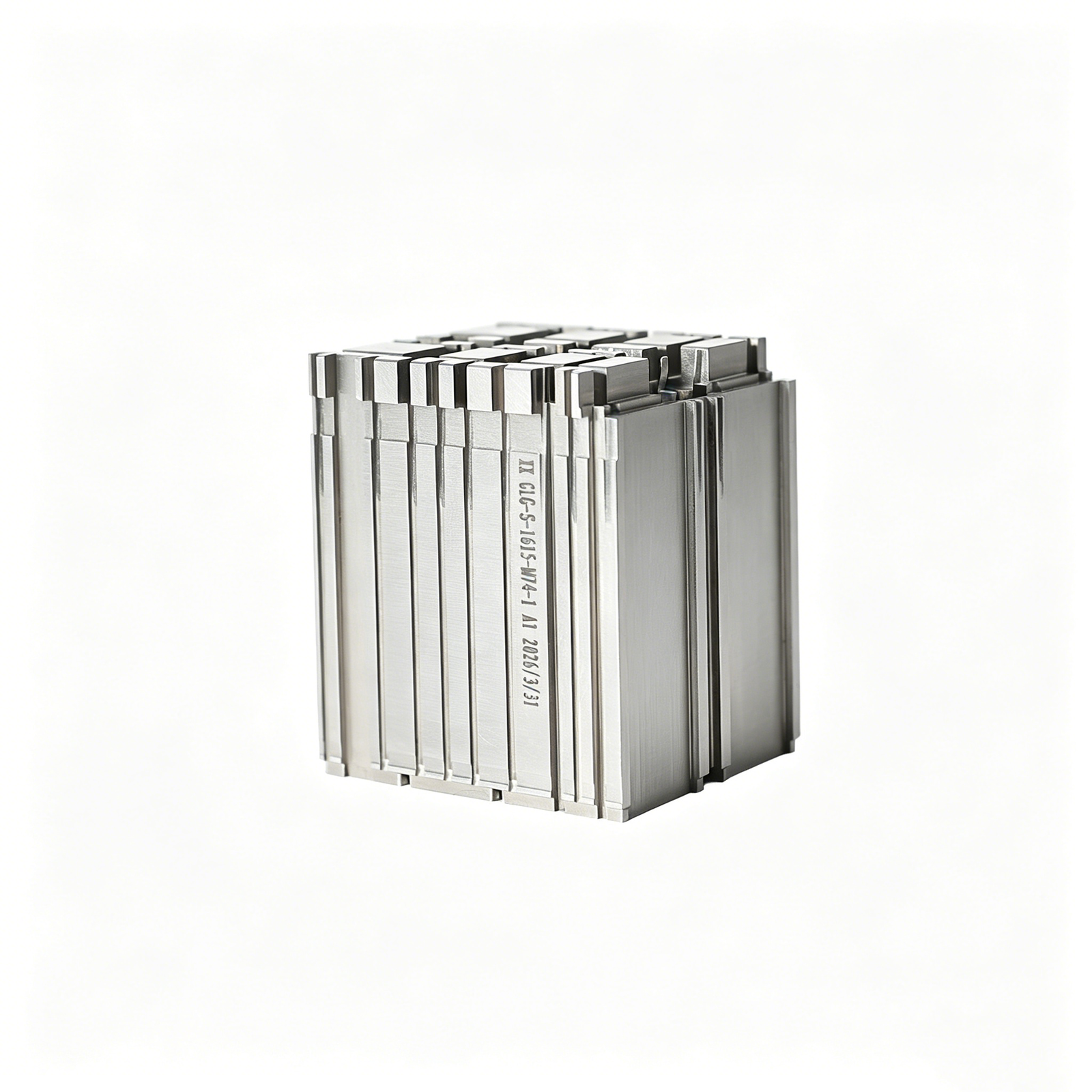


Related Configurable Components and RFQ Support









QSFP Connector Mold Inserts: Engineering Advantages
Practical controls for drawing-driven connector tooling projects, from DFM review through inspection and revision-controlled delivery.
DFM Before Quotation
Before quotation, we review datums, critical dimensions, tool access, and tolerance interactions to identify manufacturability questions while changes remain manageable.
Planned CNC Routes
CNC milling, turning, and multi-axis machining are planned around geometry, material condition, and accessible features identified in the approved drawing package.
EDM Strategy
Wire and sinker EDM strategies address narrow features and internal forms where conventional cutting access or tool geometry requires a different route.
Grinding Allowance Review
Grinding allowances and finishing sequence are reviewed to protect datum relationships, surface requirements, and final fit after heat treatment or EDM.
Inspection Planning
Inspection planning links critical features to suitable measurement methods, reporting needs, and order-specific acceptance criteria before final documentation is prepared.
Revision-Controlled Communication
Revision-controlled communication keeps drawing updates, open technical questions, inspection expectations, and delivery information visible throughout the project.
QSFP Connector Mold Inserts and Tooling Components
Match drawing-defined QSFP connector requirements to the machining, EDM, grinding, inspection, and controlled production route appropriate for critical features.

CNC Machining Services
Precision CNC machining services for drawing-based QSFP tooling components, combining milling, turning, EDM, grinding, and inspection as required by geometry, material condition, critical dimensions, and quantity.
Upload a Drawing
CNC Milling
Custom CNC milling services for insert faces, pocketed features, runner details, datum surfaces, and other prismatic QSFP mold-tooling geometry. Drawing review confirms tool access, clamping strategy, tolerances, and finishing requirements before production.
Upload a Drawing
CNC Turning
Precision CNC turning services for round QSFP connector-tooling parts such as pins, sleeves, bushings, guide elements, and stepped features. Quotations should define diameter tolerances, concentricity, surface requirements, material, and heat-treatment sequence.
Upload a Drawing
5-Axis Machining
5-axis CNC machining supports complex QSFP insert geometry where multiple angled features, compound surfaces, or restricted tool access make conventional setups inefficient. Feasibility depends on part geometry, datum strategy, cutter reach, tolerance requirements, and inspection access.
Upload a Drawing
Swiss & Micro Machining
Swiss machining and micro machining support small, slender, or detail-intensive connector-tooling components. Review the drawing for feature scale, material, aspect ratio, concentricity, burr control, and measurement method before selecting a route.
Upload a Drawing
Wire & Sinker EDM
Wire EDM and sinker EDM services address hardened materials, narrow slots, internal corners, fine profiles, and features beyond practical cutter access. Electrode strategy, wire path, recast considerations, finishing allowance, and inspection criteria should be agreed before machining.
Upload a Drawing
Precision Grinding
Precision surface and profile grinding establishes controlled flatness, parallelism, thickness, profiles, and final fits on QSFP tooling components. Grinding stock, heat-treatment condition, datums, surface requirements, and measurement method guide the process plan.
Upload a Drawing
Mold Core & Cavity Inserts
Precision mold core and cavity inserts for QSFP connector tooling are produced from customer drawings and specified materials. Critical pin geometry, cavity details, mating interfaces, EDM access, heat-treatment sequence, and inspection points require review before release.
Upload a Drawing
Ejector & Ejection Components
Ejector pins, sleeves, and ejection components support controlled release of molded QSFP connector features. Buyers should specify fit requirements, stroke-related interfaces, material condition, surface finish, and any dimensional features that affect ejection performance.
Upload a Drawing
Core Pins, Guide & Locating Components
Core pins, guide pins, and locating components establish repeatable feature formation and mold alignment. Drawings should identify functional datums, fit classes, positional relationships, material and hardness requirements, and inspection expectations for mating components.
Upload a Drawing
Slides, Lifters, Gates & Mold Accessories
Mold slides, lifters, gates, and accessories are configurable tooling families for side actions, feature release, material flow, and assembly support. Manufacturing planning considers movement interfaces, wear areas, tool access, heat treatment, and fitting requirements.
Upload a Drawing
Connector Mold Components
Precision connector mold components support QSFP connector tooling where fine pitch, mating geometry, insert alignment, and repeatability are central. Submit the 2D drawing, 3D model when available, material, critical dimensions, and application context for DFM review.
Upload a Drawing
Stamping Die Components
Precision stamping die components include drawing-defined punches, dies, guide elements, plates, inserts, and forming-related parts. Process planning accounts for material, hardness, wire-EDM profiles, grinding allowance, working edges, fits, and inspection documentation.
Upload a Drawing
Injection, MIM, CIM & Overmolding Tooling
Injection, MIM, CIM, and overmolding tooling components are evaluated according to the verified production scope and drawing requirements. Review should address material behavior, parting and gate details, insert interfaces, thermal treatment, finish, and dimensional priorities.
Upload a Drawing
Machining Materials
CNC machining materials are selected from the drawing, application conditions, required hardness, corrosion behavior, wear exposure, and downstream processing. Provide the exact material specification or approved alternatives, along with any certification or traceability needs.
Upload a Drawing
Surface Finishes & Heat Treatment
Surface finishing and heat treatment are planned around functional surfaces, corrosion or wear demands, dimensional change risk, and post-treatment machining or grinding. Specify the required process, target condition, masking needs, surface areas, and acceptance criteria.
Upload a Drawing
Quality, Metrology & Documentation
Precision inspection, metrology, and quality documentation are defined by critical dimensions, datums, tolerance stack, sampling expectations, and customer reporting needs. The inspection plan and final records should align with the released revision and purchase-order requirements.
Upload a Drawing
Prototyping & Low-Volume Production
Rapid prototyping and low-volume manufacturing support drawing-driven validation, tooling iterations, and controlled production quantities. To assess a practical route, provide revision-controlled files, material, quantity, critical dimensions, finish requirements, inspection needs, and target delivery date.
Upload a DrawingMaterials for QSFP Connector Mold Inserts

Pre-Hardened Tool Steel
A practical choice for QSFP connector mold inserts requiring stable machining before final fitting. Pre-hardened grades can support efficient CNC, EDM, and grinding routes when hardness, surface condition, and inspection requirements are defined on the drawing.

Hardenable Tool Steel
Specified for inserts that require heat treatment after rough machining. Process planning should account for distortion risk, finish stock, datum preservation, and post-treatment grinding so critical cavity, core, and locating dimensions can be verified.

Stainless Tool Steel
Considered where corrosion resistance, molding environment, or storage conditions influence material selection. The drawing should state the required grade, heat-treatment condition, surface finish, and critical features so machining and inspection methods can be aligned.

Copper Alloy Inserts
Copper-alloy inserts may be specified where thermal behavior is a design priority. Material grade, hardness condition, feature geometry, and EDM or machining access should be reviewed together, particularly around thin ribs, localized cooling, and mating interfaces.

Drawing-Specified Alloys
Additional engineering steels, aluminum alloys, or specialty materials can be evaluated from the drawing and application context. Submit material specification, heat-treatment sequence, quantity, dimensional priorities, and quality documentation needs for a responsible manufacturability review.
QSFP Connector Mold Inserts: Process Options


Wire EDM
Wire EDM creates narrow slots, sharp internal profiles, and features with limited milling access. The wire path, start holes, corner conditions, and finishing requirements should be defined against the drawing datums.

Sinker EDM
Sinker EDM supports detailed cavities, ribs, and formed features that cannot be reached efficiently by cutting tools. Electrode design, burn allowance, surface requirement, and subsequent finishing are planned with the component geometry.


Component Fitting
Fitting verifies how individual QSFP connector mold inserts relate to mating cores, slides, guides, or other tooling elements. Functional clearances and contact relationships are assessed against the approved assembly requirements.

Final Inspection
Inspection follows the agreed critical-dimension and documentation plan, using suitable methods for the specified features. Results, revision status, and any required reporting are kept aligned with the order before delivery coordination.
QSFP Connector Mold Inserts: Supporting Elements

Guide Components
Guide pins, bushings, and locating elements help establish repeatable mold-half alignment. Their dimensions, fit relationships, hardness requirements, and lubrication provisions should be reviewed with the overall connector-tooling datum strategy.

Core Pins
Core pins form narrow features, contact-related geometry, and localized internal details. Review unsupported length, machining access, EDM needs, grinding stock, and replacement strategy before committing the component design.

Cavity Inserts
Cavity and core inserts provide serviceable, configurable tooling surfaces for connector features. Split lines, venting, material selection, heat-treatment sequence, and critical dimensions should be defined on the controlled drawing.

Slides Lifters
Slides and lifters support molded features that cannot release along the primary opening direction. Travel, locking, wear surfaces, cooling interfaces, and fitting requirements need coordinated review with the mold design.

Gate Elements
Gate inserts, runners, and related tooling details influence polymer flow into fine connector geometry. Gate location, replaceability, surface finish, and machining or EDM access should be assessed against the intended molding process.

Mold Accessories
Custom stops, wear plates, spacers, retainers, and locating accessories can complete a drawing-defined tooling assembly. SUUXIANG evaluates the required interfaces, materials, tolerances, and inspection expectations rather than supplying a fixed catalogue.
QSFP Connector Mold Inserts, Drawing-Driven
Established in 2010 in Chang’an Town, Dongguan, SUUXIANG is the sole public-facing brand of Dongguan SuuXiang Precision Mold Co., Ltd., founded and legally represented by XiaoCheng Huang. We help global engineering, sourcing, and quality teams convert controlled drawings and specifications into inspected custom CNC parts, precision mold components, and connector-tooling work.
For QSFP connector mold inserts, the work begins with drawing review: critical dimensions, datums, material and heat-treatment requirements, machining access, EDM strategy, grinding allowance, and inspection needs. Our process planning combines CNC milling and turning, multi-axis machining, wire EDM, sinker EDM, precision grinding, fitting, and inspection as the project requires.
SUUXIANG is built for disciplined, drawing-based collaboration rather than generic quotations. We keep revision, manufacturing, inspection, and delivery information visible so teams can evaluate process routes, confirm quality expectations, and submit RFQs with the evidence needed for a responsible production commitment.

QSFP Connector Mold Inserts: Precision Manufacturing Control
Drawing Review and DFM
SUUXIANG reviews QSFP connector mold inserts against the drawing, 3D model, material requirements, and mating context before quotation. The discussion identifies critical dimensions, datum relationships, tool access, tolerance stack risks, and practical process routes so production commitments are based on defined requirements.
- Confirm critical-to-quality dimensions and datum strategy
- Review tool access, corner conditions, and machining allowances
- Align material, heat treatment, surface, and inspection requirements

CNC and Multi-Axis Machining
Complex connector-tooling geometry often requires more than a basic milling sequence. SUUXIANG plans CNC milling, turning, multi-axis work, micro machining, and fitting around accessible features, holding strategy, and downstream EDM or grinding requirements for configurable, drawing-based components.
- Select setups that protect functional datums
- Plan machining stages around thin walls and fine features
- Reserve stock where EDM or precision grinding is required

EDM and Grinding Strategy
For narrow slots, sharp internal features, hardened areas, or finish-critical surfaces, QSFP connector mold inserts may need a coordinated EDM and grinding route. Electrode design, wire path, recast-layer considerations, grinding stock, and heat-treatment sequence should be reviewed before machining begins.
- Evaluate wire EDM access and start-hole requirements
- Define electrode strategy for inaccessible internal geometry
- Set grinding allowance after heat treatment where applicable

Inspection and Revision Control
Inspection planning is tied to the approved drawing and identified critical features, not assumed after production. SUUXIANG keeps revision information visible through project coordination and aligns final documentation with the order requirements and verified inspection plan for clearer supplier-quality review.
- Match inspection methods to critical dimensions and datums
- Maintain traceable drawing and revision references
- Clarify reporting needs before production release

Why Choose SUUXIANG for QSFP Connector Mold Inserts
Compare drawing-led manufacturing planning with typical generic machining quotations.
← Swipe left or right to view →
QSFP Connector Mold Inserts: Precision Manufacturing Process
A drawing-led workflow that aligns DFM, controlled machining, inspection planning, and delivery coordination before parts move into production.
Review Drawings and Requirements
We review 2D drawings, models, material, quantity, critical dimensions, surface requirements, datums, application context, inspection needs, and requested delivery date.
Confirm DFM and Process Route
Our team evaluates tool access, tolerance stack, machining allowance, heat-treatment sequence, electrode strategy, wire paths, grinding stock, and practical inspection methods.
Machine Critical Component Features
Approved requirements guide CNC milling, turning, multi-axis work, micro machining, and related operations for configurable QSFP connector mold inserts and supporting components.
Apply EDM and Grinding
Wire EDM, sinker EDM, precision grinding, and fitting are planned where geometry, hardened material, surface condition, or critical feature relationships require them.
Inspect, Pack, and Coordinate Delivery
Parts are inspected against the agreed plan, matched with applicable documentation, protected for shipment, and coordinated with visible revision and delivery information.
How to Source QSFP Connector Mold Inserts
Move from drawing review to controlled production with requirements, revisions, and inspection expectations defined before release.
Send Drawings and Models
Upload the 2D drawing and available 3D model for QSFP connector mold inserts, including application context, mating features, quantity, and target delivery date.
Define Critical Requirements
Specify material, heat treatment, critical dimensions, datum scheme, surface priorities, inspection reports, and any connector-tooling constraints that affect machining, EDM, grinding, or fitting.
Review DFM and Quote
Review SUUXIANG’s proposed process route, manufacturability questions, revision assumptions, quotation scope, and sample requirement before committing the order to production.
Approve Production Release
Confirm the approved drawing revision, quality plan, delivery requirements, and agreed documentation so manufacturing, inspection, and project coordination proceed against the same controlled record.
QSFP Connector Mold Inserts Certifications and Documentation
QSFP Connector Mold Inserts: Customer Project Feedback
No approved customer testimonial is currently available for publication. SUUXIANG can share project-specific manufacturing and inspection evidence during an RFQ review when the applicable customer permissions and documentation are confirmed.
No approved application case is currently cleared for public use. Drawing review, critical-dimension requirements, inspection expectations, and delivery coordination can be discussed against the buyer’s specific QSFP connector tooling request.
Customer names, performance figures, and delivery outcomes are not published without verification and approval. Submit a drawing to discuss a controlled manufacturing plan, inspection method, and documentation requirements for the intended component.
QSFP Connector Mold Inserts FAQ
Practical guidance for engineering and procurement teams preparing drawing-based connector tooling inquiries.
What should I send for a QSFP connector mold inserts quote?
Is there a minimum order quantity for custom QSFP connector mold inserts?
Can I order a sample before full production of QSFP connector mold inserts?
How is lead time determined for connector mold components?
What materials can be reviewed for QSFP connector mold inserts?
Can SUUXIANG provide inspection reports with my order?
How are shipping and payment handled for custom machined inserts?
How is my drawing and design IP protected during quotation and production?
Complete Buyer’s Guide to qsfp connector mold inserts
Use this practical framework to define tolerances, materials, tooling interfaces, and verification needs for QSFP connector inserts—while comparing suppliers, controlling risk, and avoiding drawing, qualification, and cost mistakes before production.
1. What Are qsfp connector mold inserts?
QSFP connector mold inserts are precision tooling components used inside a mold to form, locate, support, or shape critical connector-housing features during injection molding. Depending on the design, an insert may establish contact-feature geometry, cavity details, datum faces, latch-related features, or local shutoffs.
Three distinct items should not be conflated: the mold insert is the removable or fitted tool component; an insert-molded connector assembly is a production part in which metal contacts or other components are encapsulated by resin; and a finished QSFP module is the completed pluggable product assembled for its intended interface. Each has different drawings, acceptance criteria, and revision-control needs.
0.01 mm-scale variation can be consequential where small molded features must align repeatedly with mating components, though the allowable value must come from the released drawing. Dimensional control, surface condition, and repeatable fit help prevent flash, mismatch, inconsistent seating, and premature wear across production cycles.
2. QSFP Connector Evolution and Tooling Context
Four electrical lanes made QSFP a compact route to higher aggregate port density; later variants such as QSFP-DD extend the interface to eight lanes. That change concentrates more contacts, molding features, and interface controls into a constrained envelope, so cavity-to-core alignment and contact-support geometry become tooling concerns rather than cosmetic details. https://www.molex.com/en-us/products/connectors/high-speed-pluggable-io/qsfp-connector-system
Eight-lane packaging also makes local resin behavior and heat removal relevant to dimensional stability around thin walls, retention features, and contact locations. Tooling review should therefore consider gate position, venting, cooling access, steel support, ejection direction, and the repeatability required at mating interfaces—not only nominal part dimensions.
100 host-connector and 50 module-connector mating cycles are cited minimums for QSFP-DD, illustrating why interface consistency matters through use, not merely at first inspection. The appropriate qsfp connector mold inserts design must be validated against the customer’s released drawing, resin grade, mold architecture, production conditions, CTQ datums, and agreed inspection plan before manufacture. https://blog.viavisolutions.com/2020/06/30/whats-all-this-insertion-cycle-stuff
3. Types of qsfp connector mold inserts
QSFP connector drawings should be converted into an insert map, not quoted as one generic block. Identify the molded feature, datum relationship, shutoff or wear mechanism, and replacement need for every insert.
Cavity And Core Inserts

Cavity inserts form external housing geometry; core inserts form internal pockets and contact features. Their primary risks are datum transfer, steel-safe allowance, and inaccessible machining corners.
Modular cavity or core blocks help when one connector variant changes while the mold base remains common. Define interface datums and fastening access on the drawing.
Pin, Blade, And Motion Inserts
Pin and blade inserts create narrow slots, ribs, and terminal-adjacent details. Alignment, deflection, venting, and EDM wire-path access require explicit review.
Slider- and lifter-related inserts create side features or undercuts. Replaceable tips limit repair scope after damage or design iteration.
Locating, Support, And Wear Inserts
Locating inserts establish repeatable position between insert, mold plate, and mating tooling. Support inserts resist local load and should not obscure inspection datums.
Wear inserts protect gates, shutoffs, guide faces, or high-contact areas. Specify modular replacement where service life, tuning, or revision risk is concentrated.
4. Materials for qsfp connector mold inserts
Four variables—resin abrasiveness, shot volume, cooling demand, and mold location—govern material choice for qsfp connector mold inserts. No grade is universally best; define service conditions before release.
| Material | Hardness | Wear | Machine/Polish | Corrosion | Cooling/Service |
|---|---|---|---|---|---|
| P20 | 48–52 HRC | High | Good | Moderate | General cavities |
| H13 | 48–54 HRC | High | Moderate | Moderate | Hot, high-volume areas |
| Beryllium copper | 30–40 HRC | Moderate | Good | Moderate | Local cooling inserts |
Steel Insert Choices
48–52 HRC P20 suits general inserts where polishability and stable machining matter.
48–54 HRC H13 better tolerates heat and wear; stainless tool steel helps where corrosion matters.
Copper Alloy Applications
High-conductivity beryllium-copper inserts remove heat rapidly near hot spots, but moderate wear resistance limits exposed abrasive shutoffs.
Thin copper-alloy inserts need support geometry; select them for cooling response, not as default cavity material.
Heat Treatment And Coatings
Through-hardening and tempering establish core hardness after rough machining; retain grinding stock for final geometry.
PVD coatings can reduce sliding wear or galling, but must match substrate hardness, resin, and surface-finish requirements.
5. Customizing qsfp connector mold inserts
Customization begins with the released 2D drawing, 3D model, resin context, and CTQ dimensions. For qsfp connector mold inserts, SUUXIANG should convert these inputs into a datum-based machining and inspection plan before production.
Datums And Functional Interfaces
Primary, secondary, and tertiary datums should locate cavity features, mating faces, and interchangeable insert seats. Gate-adjacent edges, vent lands, shutoffs, and cooling connections require explicit coordinates and access checks.
A DFM review should flag thin steel, inaccessible milling paths, electrode requirements, and wire-EDM reliefs before machining.
Tolerances And Surface Requirements
Critical dimensions need feature-level tolerances tied to their functional datum scheme, rather than a blanket tight-tolerance note. Surface finish must distinguish sealing, sliding, cavity, and nonfunctional faces.
Grinding stock, heat-treatment sequence, EDM recast removal expectations, and measurement method should be agreed where they affect final size.
Identification And Revision Control
Functional marks can include insert ID, cavity number, revision, orientation, and material or hardness reference when specified. Mark location and depth must avoid cosmetic surfaces, sealing lands, and stress-sensitive geometry.
Each revision should identify changed dimensions, affected mating inserts, inspection updates, and disposition of prior parts. SUUXIANG can align final documentation with the approved drawing revision and inspection plan.
6. Critical Construction and Quality Elements
Two datums, rather than a chain of local dimensions, should locate the cavity, contact features, and mating interfaces. For qsfp connector mold inserts, repeatable molded geometry depends on that datum scheme surviving machining, fitting, and inspection.
Datum And Fit Control
Three checks matter at assembly: datum-to-feature position, insert seating, and controlled clearance at moving or mating interfaces. Specify the functional datum order on the approved drawing, not only nominal coordinates.
0.01 mm can be consequential in dense connector features, but the allowable value must come from the design tolerance stack. Corner radii, wire paths, tool access, and grinding stock should be reviewed before release.
Edges, Vents, And Surfaces
Two edge conditions require definition: deburr limits and any intentionally sharp shutoff or sealing edge. Uncontrolled edge break, flash-prone vent geometry, or a polish direction crossing material flow can change part release and cosmetic consistency.
1 surface callout should identify the functional area, required finish, and polishing direction. Vent depth and land geometry require validation against the specified resin, molding conditions, and approved tool design.
Wear And Evidence
Four records can anchor production approval: dimensional report, specified material certificate, hardness result when required, and first-article verification against the approved drawing. They should identify revision, measurement method where applicable, and nonconformances.
1 wear plan should focus on high-contact, sliding, gate, and shutoff areas. Hardness, surface treatment, replacement strategy, and inspection frequency must follow the application requirement rather than assumed capability.
7. How to Choose a Mold-Insert Manufacturer
2D drawings and 3D models reveal whether a supplier can discuss datums, tolerance chains, tool access, and inspection before quoting. For qsfp connector mold inserts, evaluate project evidence rather than capability statements.
Review Drawing Comprehension
2D drawings should receive a documented review identifying CTQ dimensions, datum references, EDM or grinding needs, and unresolved notes.
Before PO release, engineering and procurement should ask: Which dimensions drive the process route, and what clarification is required?
Verify Process And Measurement
CNC, wire EDM, sinker EDM, and grinding should be proposed against actual geometry, hardened condition, and required surface features.
First-article evidence can include material identification, heat-treatment records when specified, inspection results, and the method used for each critical feature.
Control Delivery And Changes
1 revision-controlled traveler should connect the released drawing, inspection plan, sample approval, and packaging instructions. Request realistic lead-time assumptions, protective packaging details, and escalation ownership.
8D-style corrective-action records are more useful than assurances after a nonconformance. Ask how a drawing revision is acknowledged, segregated, and communicated before production resumes.
8. Common qsfp connector mold insert Buying Mistakes
Eight release errors repeatedly create avoidable rework in qsfp connector mold inserts. Resolve them in the controlled drawing-review package before material is ordered or electrodes are programmed.
Datum And Mating Context
Two datum references without a functional mating view can shift the true connector interface. Provide assembly sections, contact positions, and the datum scheme used for acceptance.
Stack And Material Decisions
One tight feature can be meaningless when adjacent insert, housing, and contact tolerances accumulate. Review the full tolerance stack, then select steel against resin, cycle volume, wear, and heat-treatment route—not initial price.
Drawing And Inspection Release
A 3D CAD model may omit GD&T, surface requirements, revision status, and inspection criteria. Release an approved 2D drawing with critical dimensions, measurement method, report requirements, and controlled revision.
Wear Insert Planning
High-wear gates, shutoffs, and locating features can turn a minor repair into a mold-down event. Identify replaceable wear inserts and specify spare quantities, interchangeability datums, and acceptance criteria before release.
9. From Drawing Release to Production Approval
A controlled release package prevents a quotation from becoming an uncontrolled production instruction. For qsfp connector mold inserts, the release path should assign decision ownership and preserve each approval against its drawing revision.
Release The Technical Package
Revision A files should include the 2D drawing, 3D model, application context, mating interfaces, quantity, and target date. Design owns geometry; procurement controls the RFQ package; SUUXIANG records receipt and identifies missing inputs.
Close DFM And Quality
100% of critical dimensions should be identified before order release, with datums, material, heat treatment, finish, and inspection method stated. SUUXIANG returns DFM and quotation comments; design approves manufacturability while quality approves the inspection plan.
Approve First Article
First-article approval should reference the part number, drawing revision, sample quantity, measured results, deviations, and disposition. Quality signs acceptance or conditional acceptance; procurement issues the production release only after documented approval.
Control Changes And Replenishment
Each revision change needs a new controlled file, change summary, effective quantity, and written acknowledgement from design, quality, procurement, and supplier. Replenishment should cite the last approved revision, inspection requirements, and any approved deviation expiry.
10. Pricing and Cost Drivers
Two cost patterns dominate qsfp connector mold inserts: prototypes absorb programming, fixturing, electrodes, and inspection setup; repeat orders can spread those activities across more parts. Larger envelopes, restricted tool access, thin features, tighter tolerances, hard materials, heat treatment, EDM, grinding, and specialized finishes each change the process route.
One reviewed technical package is the basis for final pricing. A dimensioned drawing, 3D model, material and hardness, quantity, critical datums, finish, inspection plan, and revision level reduce quotation uncertainty and prevent scope changes after release.
| Order profile | Primary cost drivers | Pricing implication |
|---|---|---|
| Prototype: 1–5 pieces | Setup, CAM, fixture or electrode design, first-article inspection | Highest unit cost; technical risk is resolved early |
| Low volume: 6–50 pieces | Cycle time, EDM or grinding content, heat-treatment sequence, inspection scope | Setup is shared, but complex geometry remains material |
| Repeat order: 50+ pieces | Stable revision, batch size, material purchasing, documented inspection method | Lower unit cost is possible when the approved route is reused |
Upload Your QSFP Connector Mold Inserts Drawing
Include material, quantity, critical dimensions, inspection requirements, and delivery target for a disciplined DFM and quotation review.