
QSFP112 Connector Mold Inserts, Reviewed Before Machining
Send your drawings for DFM-led quotation, critical-dimension planning, and inspected QSFP112 connector mold inserts built to your documented requirements.
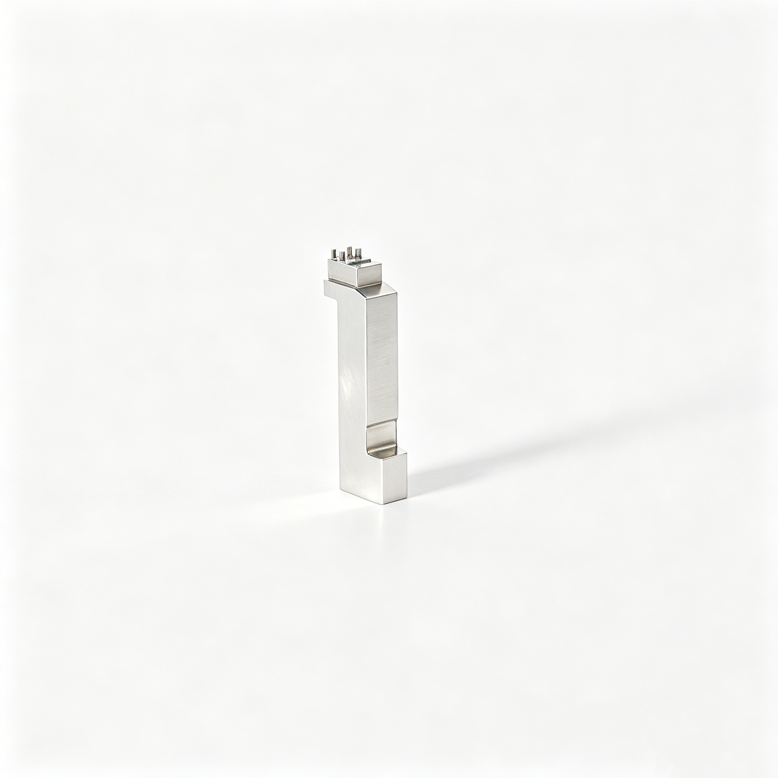
Featured Components for QSFP112 Connector Mold Insert Development








Related Component Families and Quotation









Why Choose SUUXIANG for QSFP112 Connector Mold Inserts
A drawing-led workflow that aligns manufacturability, critical dimensions, process routing, inspection, and revision control before production commitments.
Drawing-Led DFM Review
We review drawings, models, datums, tool access, and critical features to identify manufacturability questions before quotation and production planning.
Coordinated Process Routing
CNC machining, EDM, precision grinding, and fitting are planned together around geometry, access constraints, machining allowance, and surface requirements.
Critical Dimension Planning
Your QSFP112 connector mold inserts are reviewed around critical dimensions, tolerance relationships, datum strategy, and appropriate inspection methods.
Inspection Matched to Requirements
Inspection planning follows the order requirements, focusing on agreed dimensions, surface priorities, reporting needs, and traceable measurement evidence.
Visible Revision Control
Drawing revisions, manufacturing questions, and delivery information stay visible throughout project coordination, helping teams avoid producing against outdated requirements.
QSFP112 Inserts and Supporting Tooling Families
Drawing-driven component families for connector molds and related tooling, planned around critical geometry, process access, inspection requirements, and controlled revisions.

CNC Machining Services
Precision CNC machining services translate approved drawings into custom machined parts, tooling, and production components. Process planning reviews material, datums, critical dimensions, machining access, and inspection needs before a route combining milling, turning, EDM, grinding, or fitting is selected.
Upload a Drawing
CNC Milling
Custom CNC milling services support prismatic inserts, plates, mold bases, and contoured features. Tool access, clamping strategy, corner radii, surface requirements, and remaining grinding stock are reviewed to protect functional geometry through machining and inspection.
Upload a Drawing
CNC Turning
Precision CNC turning services produce rotational features such as pins, sleeves, bushings, and locating elements. Diameter tolerances, concentricity, thread details, shoulder relationships, material condition, and later grinding or heat-treatment requirements should be defined in the drawing package.
Upload a Drawing
5-Axis Machining
5-axis CNC machining helps reach compound surfaces, angled details, and multi-face geometry with fewer setups. For connector tooling, the route is assessed against tool reach, fixture stability, datum transfer, finish requirements, and whether EDM remains necessary.
Upload a Drawing
Swiss & Micro Machining
Swiss machining and micro machining address small, slender, or detail-dense components where support and handling affect results. Review should identify critical diameters, length-to-diameter relationships, burr control, feature accessibility, and the inspection method required for acceptance.
Upload a Drawing
Wire & Sinker EDM
Wire EDM services and sinker EDM services form narrow slots, sharp internal geometry, hardened details, and inaccessible features that conventional cutters cannot reach reliably. Electrode strategy, wire path, flushing, corner condition, recast-layer considerations, and finish expectations require early review.
Upload a Drawing
Precision Grinding
Precision surface and profile grinding establishes controlled flatness, parallelism, profiles, and final stock removal on functional tooling surfaces. The plan considers heat-treatment movement, grinding allowance, datum sequence, wheel access, surface requirements, and inspection of critical relationships.
Upload a Drawing
Mold Core Inserts & Mold Cavity Inserts
Precision mold core and cavity inserts are configured from part geometry, resin behavior, molding features, and maintenance needs. Drawing review should address shutoffs, venting, cooling interfaces, steel selection, finish zones, EDM detail, and inspection criteria before manufacture.
Upload a Drawing
Ejector & Ejection Components
Ejector pins, sleeves, and ejection components must move freely while protecting molded features from marking or deformation. Specifications should define fit relationships, working surfaces, hardness and finish needs, stroke context, lubrication considerations, and mating-component dimensions.
Upload a Drawing
Core Pins, Guide & Locating Components
Core pins, guide pins, and locating components establish repeatable relationships between mold elements. Their drawings should identify datum strategy, fit class, engagement length, alignment function, wear surfaces, material condition, and the inspection points that govern assembly performance.
Upload a Drawing
Slides, Lifters, Gates & Mold Accessories
Mold slides, lifters, gates, and accessories are planned as interacting mechanisms rather than isolated parts. Geometry review considers travel, clearances, shutoff conditions, gate location, wear surfaces, assembly datums, and fitting requirements needed for stable molding operation.
Upload a Drawing
Connector Mold Components
Precision connector mold components support tightly spaced cavities, terminal features, insulation geometry, and repeatable molding alignment. The manufacturing review focuses on fine details, steel condition, EDM access, polishing boundaries, mating interfaces, critical dimensions, and inspection evidence.
Upload a Drawing
Stamping Die Components
Precision stamping die components are produced for forming, blanking, piercing, guiding, and locating operations. Process decisions depend on material and hardness, cutting-edge geometry, clearance relationships, grinding sequence, surface finish, assembly fit, and dimensional traceability.
Upload a Drawing
Injection, MIM, CIM & Overmolding Tooling
Injection, MIM, CIM, and overmolding tooling components are evaluated against the specific molding process and part behavior. Reviews can address feature definition, feed or gate interfaces, shrinkage inputs, material requirements, tool access, finishing, fitting, and inspection plans within verified scope.
Upload a Drawing
Machining Materials
CNC machining materials are selected against function, machinability, wear, corrosion exposure, heat-treatment route, and required documentation. Buyers should specify material grade, condition, approved substitutions, application environment, and any traceability requirement before quotation and production planning.
Upload a Drawing
Surface Finishes & Heat Treatment
Surface finishing and heat treatment are coordinated with dimensions, wear requirements, corrosion resistance, cosmetic areas, and subsequent grinding or polishing. The drawing should state the required process, affected surfaces, target condition, masking needs, and inspection or certification documentation.
Upload a Drawing
Quality, Metrology & Documentation
Precision inspection, metrology, and quality documentation are planned from the drawing’s critical-to-quality features. Requirements may include dimensional reports, datum-based measurement methods, material records, revision confirmation, and order-specific documentation aligned with the verified inspection plan.
Upload a Drawing
Prototyping & Low-Volume Production
Rapid prototyping and low-volume manufacturing support drawing-based evaluation, tooling development, and controlled production quantities. An effective RFQ includes models, quantities, material and heat-treatment requirements, critical dimensions, surface priorities, delivery target, and inspection expectations.
Upload a DrawingMaterials for QSFP112 Connector Mold Inserts

Pre-Hardened Tool Steel
A practical option for connector mold components requiring balanced machinability and stable service performance. Grade selection, hardness condition, finishing allowance, and critical dimensions should be confirmed against the approved drawing and molding application.

Hardened Tool Steel
Considered for inserts exposed to repeated wear, localized pressure, or demanding shutoff geometry. Heat-treatment sequence, EDM strategy, grinding stock, and final inspection datums require coordinated review to protect critical connector features.

Stainless Tool Steel
May suit mold components where corrosion resistance and polished functional surfaces are relevant. The specific grade, heat-treatment condition, surface finish, and mating-material environment should be evaluated from project documentation before manufacture.

Copper Alloy Inserts
Used selectively where heat-transfer behavior is a design priority around a molding feature. Alloy choice, support geometry, joining method, machining access, and wear exposure need drawing-based assessment before this route is specified.

Tungsten Carbide Inserts
A candidate for concentrated wear areas and demanding small-feature applications. Its material behavior changes machining, EDM, fitting, and inspection planning, so SUUXIANG reviews geometry, tolerances, and interface conditions before confirming feasibility.
QSFP112 Connector Mold Inserts: Supported Precision Manufacturing Processes


Wire EDM
Wire EDM produces fine through-features, precise profiles, and difficult internal geometries after suitable access and start-hole provisions are reviewed. The route considers wire path, corner conditions, datum transfer, and finishing allowances.

Sinker EDM
Sinker EDM forms enclosed cavities, sharp internal features, and geometries beyond practical cutter access. Electrode design, spark allowance, surface requirement, and downstream polishing or fitting needs should be confirmed before production.


Tooling Fitting
Fitting verifies how inserts, pins, slides, and related tooling elements assemble against their intended datums. Controlled handwork addresses agreed contact and movement requirements without replacing the dimensions defined by the drawing.

Final Inspection
Inspection is planned around drawing-critical dimensions, surface requirements, and specified reporting needs. Results are documented against the agreed revision so engineering, sourcing, and quality teams can review delivered QSFP112 connector mold inserts clearly.
QSFP112 Connector Mold Inserts: Tooling Accessories

Core Pins
Precision core pins can form small connector features where diameter, concentricity, material condition, and replacement strategy are defined. Review unsupported length, EDM access, heat-treatment sequence, and measurement method with the mating insert.

Guide Elements
Guide pins, bushes, and wear-guidance elements support repeatable mold alignment during closing and cycling. Selection should reflect load direction, clearance, lubrication approach, mounting geometry, and the relationship to critical QSFP112 connector mold inserts.

Locating Components
Locating pins, keys, and datum features establish controlled orientation between inserts, plates, and fixture references. Provide datum definitions and positional tolerances so machining, fitting, and final inspection can follow the intended assembly relationship.

Slides And Lifters
Slides and lifters may create side features or controlled release paths when the approved mold design requires them. SUUXIANG reviews travel, interference risk, bearing surfaces, fit allowances, and inspection priorities from project-specific drawings.

Gate Components
Gate inserts, bushings, and related feed-area components can be considered for mold projects with defined resin flow and service requirements. Share gate geometry, material, surface condition, thermal considerations, and replacement expectations for review.

Ejection Parts
Ejector pins, sleeves, and return-related components support controlled part release in an assembled tool. Their fit, surface condition, stroke interface, and location relative to delicate connector geometry should be confirmed through the drawing package.
About QSFP112 Connector Mold Inserts
SUUXIANG is the international-facing brand of Dongguan SuuXiang Precision Mold Co., Ltd., established in 2010 and based at the 2nd Floor of Sanhe Industrial Park, Chang’an Town, Dongguan, Guangdong, China. XiaoCheng Huang is the founder and legal representative. We help engineering, sourcing, and quality teams translate drawings, models, and specifications into inspected precision components for connector tooling, molds, dies, and custom CNC manufacturing.
For qsfp112 connector mold inserts, our planning brings CNC milling and turning, multi-axis machining, wire and sinker EDM, precision grinding, fitting and inspection into a controlled process route. Before quotation or production commitments, we review critical dimensions, datums, material requirements, tool access, EDM needs, grinding allowance and inspection expectations.
What distinguishes SUUXIANG is disciplined project communication around the details that affect part performance and delivery. We keep revision control, manufacturing decisions and inspection requirements visible, so buyers can align drawing intent, quality evidence and delivery needs before production begins.

Core Capabilities for QSFP112 Connector Mold Inserts
DFM and Datum Review
QSFP112 connector mold inserts begin with a drawing-led review of critical dimensions, datums, mating geometry, tolerances, and surface requirements. The review identifies ambiguous callouts and manufacturability risks before quotation, helping align the process route with the intended connector-tooling function.
- Confirm functional datums and critical-to-quality features
- Review tolerance stack and feature accessibility
- Clarify mating, shutoff, and insert-interface requirements
- Record drawing revisions before production planning

Process Route Planning
SUUXIANG plans each insert around its geometry, material condition, heat-treatment sequence, and required finishing operations. CNC milling, turning, multi-axis machining, EDM, grinding, and fitting are assigned according to tool access and the dimensions that must be controlled through each stage.
- Match machining routes to geometry and access
- Plan stock allowance for later grinding or EDM
- Consider heat treatment within the dimensional sequence
- Define handoff points between machining operations

EDM and Grinding Strategy
For narrow ribs, deep details, sharp internal forms, or hard-material features, electrode design and wire paths must be considered early. Grinding strategy is equally important where flatness, parallelism, or controlled final stock affects fit, sealing, or repeatable mold assembly.
- Evaluate electrode access and burn sequence
- Review wire-EDM start holes and path constraints
- Protect grinding stock through earlier operations
- Coordinate fitting requirements with finished surfaces

Inspection Plan Alignment
Inspection planning links the drawing to a practical verification method before QSFP112 connector mold inserts move into production. SUUXIANG identifies measurable critical features, applicable datums, reporting expectations, and revision-controlled documentation so the final records correspond to the ordered part and agreed inspection plan.
- Define inspection methods for critical dimensions
- Align measurement setup with drawing datums
- Confirm report and traceability requirements
- Keep revision status visible through delivery

QSFP112 Connector Mold Insert Supplier Evaluation Checklist
Use these drawing-review, process-planning, inspection, and revision-control questions when evaluating a supplier for connector-tooling components.
← Swipe left or right to view →
QSFP112 Connector Mold Inserts: From Drawing Review to Delivery
A drawing-driven sequence that keeps critical dimensions, process decisions, inspection requirements, and revision status visible before shipment.
Review RFQ Package
Confirm the 2D drawing, 3D model, material, quantity, critical dimensions, surface requirements, delivery target, and inspection documentation needed for the requested component.
Plan Process Route
Assess datum strategy, tool access, machining allowance, heat-treatment sequence, electrode needs, wire path, grinding stock, and fitting requirements before production commitment.
Machine Critical Features
Apply the approved CNC milling, turning, multi-axis, micro-machining, or EDM route to form insert geometry while maintaining revision-controlled manufacturing information.
EDM Grind and Fit
Use wire EDM, sinker EDM, precision grinding, and fitting where required to finish detailed profiles, controlled interfaces, and functionally relevant mold features.
Inspect Pack Coordinate
Verify parts against the agreed inspection plan, prepare order-matched documentation, protect finished QSFP112 connector mold inserts in packing, and coordinate delivery information.
How to Work With SUUXIANG
Move QSFP112 connector mold inserts from drawing review to inspected delivery through a controlled, drawing-driven workflow.
Submit Your Drawing Package
Provide 2D drawings, available 3D models, quantity, application context, target date, and QSFP112 connector mold insert requirements for an initial technical review.
Define Critical Requirements
Confirm material, heat treatment, critical dimensions, datums, surface requirements, mating features, inspection needs, and revision status before production commitments are made.
Review DFM and Quotation
Evaluate the proposed machining, EDM, grinding, and inspection route, including tool access, electrode strategy, tolerances, delivery assumptions, and any manufacturability questions.
Approve Production Details
Align on the controlled drawing revision, agreed quality plan, sample or first-article expectations where applicable, and communication milestones before manufacturing begins.
Coordinate Inspection and Delivery
Receive order-specific inspection documentation and delivery updates aligned with the verified plan, while keeping technical changes and shipment requirements visible.
QSFP112 Connector Mold Inserts: Quality Documentation and Certification Evidence
QSFP112 Connector Mold Inserts: Customer Project Feedback
Approved customer feedback for QSFP112 connector mold inserts will be published here only after the customer confirms the quotation, application context, and attributable project outcome.
This reserved case record will document the drawing review scope, critical dimensions, manufacturing route, inspection evidence, and any customer-approved outcome without disclosing confidential program details.
SUUXIANG will publish customer feedback only when the source, role, company approval, and stated result can be verified against the completed precision manufacturing project record.
QSFP112 Connector Mold Inserts FAQ
Practical answers for engineering, sourcing, and quality teams preparing a drawing-based connector-tooling RFQ.
What information should I send for qsfp112 connector mold inserts?
Is there a minimum order quantity for qsfp112 connector mold inserts?
Can SUUXIANG review my qsfp112 connector mold inserts drawing before quoting?
Can you provide samples before a production order?
How should I plan lead time for precision connector mold components?
Can I request inspection reports and traceability documents?
How are drawing revisions and confidential files handled?
What payment and shipping details should be confirmed before ordering?
Customer Feedback Verification Policy
A practical decision framework for specifying precision inserts, comparing supplier capabilities, controlling validation risk, and avoiding drawing, material, tolerance, and launch mistakes in high-speed connector tooling programs.
1. What Are qsfp112 connector mold inserts?
QSFP112 is a four-lane QSFP form-factor system intended for 112 Gb/s-per-lane signaling and a 400G interconnect ecosystem, as described by the QSFP112 MSA (http://qsfp112.com). qsfp112 connector mold inserts are precision tooling elements that form the thermoplastic geometry of connector housings and related high-speed interconnect parts; they are not the finished connector, contacts, cage, or module.
Four functional insert types commonly divide the molding work: cavity inserts form exterior surfaces, core inserts form internal geometry, sliders release side features, and pins create small holes or passages. Insert-molded features instead retain or locate a separate component during molding, so their datum relationship and thermal behavior require separate review.
At SUUXIANG, drawing review should identify the dimensions governing contact-location features, mating interfaces, retention details, and assembly clearances before selecting CNC, EDM, grinding, fitting, and inspection steps. Surface condition, parting-line control, and repeatable insert seating matter because variation in the molded housing can change fit, support geometry, or the positional consistency surrounding signal-critical interfaces.
2. QSFP112 Evolution and Tooling Demands
112 Gb/s per lane is the QSFP112 MSA target for a four-lane QSFP system, enabling a 400G interconnect ecosystem. The MSA positions it as an evolution of legacy QSFP 40G, 100G, and 200G modules while preserving acceptance of those modules in the intended connector-and-cage family (http://qsfp112.com).
76 pads are used by the QSFP-DD edge connector—38 on each side of its paddle card—while the shared hardware specification addresses QSFP112 mechanical, electrical, and thermal requirements. It identifies QSFP112 as an improved QSFP+ form factor for 100 Gb/s-per-lane operation and 400 Gb/s aggregate bandwidth (http://www.qsfp-dd.com/wp-content/uploads/2022/07/QSFP-DD-Hardware-Rev6.3-final.pdf).
400G-class signaling tightens the practical interaction among connector geometry, cage alignment, thermal paths, and EMI interfaces. Mold inserts must therefore be reviewed against current datum schemes, shutoffs, pin and cavity locations, venting, and tool access; legacy QSFP tooling assumptions should not be copied without checking the applicable revision, mating hardware, and inspection plan.
3. Types of qsfp112 connector mold inserts
Six insert families determine how a QSFP112 connector tool is built, serviced, and revised. Drawing review should assign each feature a molding function, failure exposure, datum scheme, and replacement boundary before machining.
| Insert Category | Molding Role | Failure Exposure | Required Drawing Information |
|---|---|---|---|
| Cavity and core | Forms housing | Wear; dimensional drift | Datums; profiles; draft |
| Interchangeable detail | Local revision or repair | Mismatch; leakage | Replacement boundary; revision |
| Contact support | Locates terminal features | Pin shift; damage | Pin positions; mating geometry |
| Shutoff and seal-off | Controls flash boundary | Flash; galling | Shutoff angle; venting |
| Slider or lifter | Forms undercut | Interference; wear | Travel; clearance; actuation |
| Prototype or bridge-tool | Supports early builds | Frequent revision | Quantity; revision ID; acceptance |
Forming Inserts

Cavity and core inserts form the housing geometry; wear, flash, and dimensional drift are their primary exposures. Specify parting line, datums, draft, shrinkage basis, critical profiles, and texture limits.
Contact And Shutoff Features
Terminal-support, contact-support, shutoff, and seal-off inserts control delicate interfaces. Pin locations, steel-safe direction, mating geometry, allowable flash, venting, and electrode access belong on the drawing.
Moving And Development Details
Slider or lifter details create undercuts; prototype or bridge-tool inserts support controlled early changes. Define travel, clearance, wear faces, actuation datum, expected quantity, and revision identifiers.
4. Materials for qsfp112 connector mold inserts
Four inputs—resin chemistry, filler level, cycle temperature, and planned shot count—should set the insert material decision. qsfp112 connector mold inserts need hardness, polish, heat transfer, and repairability balanced against the actual molding duty.
| Material route | Strengths | Typical use |
|---|---|---|
| Hardened tool steel | Wear resistance; stable edges | High-volume or filled-resin features |
| Pre-hardened steel | Machinability; shorter rework path | Prototype and moderate-volume inserts |
| Stainless tool steel | Corrosion resistance; polishability | Corrosive environments or cosmetic surfaces |
| Copper alloy insert | Thermal conductivity | Localized cooling support |
| Surface coating | Wear or release improvement | Validated high-friction contact areas |
Select By Molding Duty
Filled resins raise abrasive wear; humid or corrosive resin systems raise corrosion risk. Confirm both before naming a steel grade.
Low-volume trials can favor easier machining, while sustained production often justifies hardened or corrosion-resistant routes.
Use Specialty Materials Carefully
Copper alloys can improve local heat extraction, but their lower wear resistance usually requires protected, non-contact locations. Coatings may reduce wear or sticking only after substrate, surface finish, and maintenance strategy are defined.
Verify The Material Plan
One drawing review should identify resin, glass or mineral content, molding temperature, cycle target, expected volume, polishing requirement, and repair history. SUUXIANG can assess the process route against those project inputs.
5. Custom qsfp112 connector mold insert features
Custom qsfp112 connector mold inserts should be configured from controlled drawings, not from a generic feature list. SUUXIANG reviews functional geometry, processing access, and inspection evidence before confirming a route.
Micro Geometry And Interfaces
A 2D drawing should identify micro ribs, shutoffs, gate land, vent interfaces, tolerances, and datum references.
A 3D model should show mating components and tool-access constraints. Tight internal corners or inaccessible electrodes can require EDM, smaller tools, or revised radii.
Wear Zones And Surfaces
Replaceable wear zones should be separated where repeated contact or abrasive resin makes serviceability important.
Surface finish and any coating requirement must name the functional area. Polish, texture, coating thickness, and post-treatment dimensions can change fit.
Marks And Inspection Control
Functional marks can identify cavity, revision, orientation, or inspection status; cosmetic decoration should not compromise a sealing or mating surface.
Revision history, critical tolerances, resin grade, and required report identifiers should accompany the RFQ. SUUXIANG can align marking and inspection plans to the released drawing.
6. Construction Quality Elements That Matter
Before cutting steel, convert ‘high precision’ into drawing-based acceptance criteria. For qsfp112 connector mold inserts, each criterion needs a datum, limit, inspection method, and revision-controlled record.
Datums And Critical Features
Three mutually perpendicular datums should locate cavity, connector-interface, and mounting features before GD&T is applied.
Each critical dimension should state its tolerance, measurement method, and sampling requirement; ambiguous datums can create mismatch and inconsistent connector fit.
Shutoffs, Edges, And Flow
A shutoff must specify contact land, allowable mismatch, and edge condition; insufficient support promotes flash and early wear.
Specified edge radii, vent depth, and gate location must preserve fill path and air escape; poor relationships can cause short shots or witness defects.
Finish, Treatment, And Verification
A stated surface-finish value and measurement direction prevent subjective polish acceptance and reduce friction-related wear.
Heat treatment, coating adhesion, alignment, and interchangeability need order-specific limits. Measurement access must be designed into the insert so critical features remain inspectable after finishing.
7. How to Choose a Mold Insert Manufacturer
Two teams—engineering and procurement—should evaluate the same drawing, not separate quotations. For qsfp112 connector mold inserts, award decisions should connect manufacturability evidence, quality planning, and a dated delivery path.
| Evaluation Area | Ask Jointly | Evidence Before Award |
|---|---|---|
| Drawing review | Are CTQs and datums understood? | Marked-up revision |
| Process fit | Which CNC, EDM, grinding route? | Process outline |
| Quality control | How is each CTQ verified? | Inspection plan |
| Program control | How are changes communicated? | Revision log and schedule |
Drawing Review Discipline
Before award, request a marked-up drawing that identifies datums, CTQs, tool access, EDM strategy, grinding stock, and assumptions. One quotation should name the exact revision reviewed.
- Ask how tolerance stacks affect mating features.
- Confirm material and heat-treatment requirements.
- Record unanswered drawing questions before release.
Process And Quality Evidence
Three capability areas—multi-axis CNC, EDM, and precision grinding—must fit the feature geometry, material condition, and finish requirement. Request equipment-relevant process planning rather than a generic capability statement.
- Material certificates and lot traceability
- Inspection plan and measurement method
- First-article report sample
Build Collaboration And Control
One controlled revision log should connect drawing changes, samples, inspection results, and shipment status. SUUXIANG can quote from drawings when buyers provide application context, quantities, and documentation expectations.
- Named technical communication owner
- Dated lead-time assumptions
- Sample and mold-build feedback path
8. Common qsfp112 connector mold insert Mistakes
Eight preventable release errors repeatedly cause QSFP112 insert rework, delayed trials, or weak acceptance evidence. Close them before the PO by converting assumptions into drawing notes, measurable criteria, and approved revision records.
Incomplete Design Inputs
2D geometry alone can hide molding conditions. Omitting resin grade and glass-fill percentage can change shrinkage assumptions and steel-safe decisions.
Before release, provide resin, filler, colorant restrictions, mating context, and the controlled 3D model.
Tolerance And Datum Gaps
Unrealistic bilateral tolerances raise cost without protecting function. Undefined primary, secondary, and tertiary datums make inspection results non-comparable.
Before PO release, identify CTQ dimensions, datum scheme, allowable measurement method, and any functional gauges.
Finish And Service Oversights
Surface finish affects release, wear, venting, and optical appearance; it is not merely cosmetic. Poor maintenance access can turn a minor insert repair into extended tool downtime.
Before trial molding, specify finish location and direction, polish limits, replaceable wear items, and access for cleaning or extraction.
Approval And Price Shortcuts
Unit price excludes the cost of undocumented assumptions, rejected parts, and revision loops. Approval without inspection criteria leaves acceptance open to interpretation.
Before award, approve a revision-controlled drawing, inspection plan, report format, sample quantity, and change-control path; compare suppliers on this evidence as well as price.
9. Steps to Launch a Tooling Program
A 9-gate launch sequence keeps qsfp112 connector mold inserts aligned to the released drawing, not verbal assumptions. Assign one revision owner and record decisions in a time-stamped action log.
| Stage | Decision Gate | Input And Owner | Output |
|---|---|---|---|
| NDA and capture | Scope released | NDA, RFQ; buyer | Controlled package |
| DFM review | Risks accepted | Datums, CTQs; engineering | Marked-up review |
| Quote alignment | Commercial approval | Route, quantity; procurement | Aligned quotation |
| Manufacturing plan | Plan released | Materials, controls; manufacturer | Process plan |
| First article | Dimensions accepted | Inspection plan; quality | FAI record |
| Mold tryout | Feedback closed | Trial results; mold team | Action list |
| Change control | Revision approved | ECR; revision owner | Released revision |
| Pilot approval | Pilot accepted | Pilot evidence; buyer | Production release |
| Repeat planning | Order releasable | History, wear; quality | Maintenance plan |
Freeze The Technical Baseline
Gate 1 freezes the controlled RFQ package before DFM begins. The buyer supplies models, drawings, application context, material, quantity, and inspection needs.
Close The Feedback Loop
Gate 6 converts mold-tryout findings into numbered, dispositioned actions. The program manager confirms whether each change affects form, fit, function, cost, or timing.
Maintain Repeatability
Gate 9 preserves approved process knowledge for repeat orders. The supplier-quality engineer reviews wear, inspection history, and revision status before release.
10. qsfp112 connector mold inserts Pricing
USD 600–1,200 per insert is an illustrative prototype range for a straightforward QSFP112 connector mold insert, before material, tolerance, and inspection requirements are confirmed.
±0.005 mm features, thin ribs, micro details, EDM electrodes, grinding, hardened material, fine finish, and CMM reporting can move cost materially; final pricing also depends on quantity and revision maturity.
2 quotations with similar unit prices may carry different program risk. Compare included process route, datum-based inspection, documentation, engineering-change handling, packaging, and delivery assumptions—not only the quoted part price.
| Illustrative tier | Quantity / complexity | Indicative unit price (USD) | Typical lead time | Included / excluded |
|---|---|---|---|---|
| Prototype | 1–2, simple geometry | 600–1,200 | 10–20 working days | Machining and basic inspection; excludes heat treatment, special finish, freight |
| Pilot | 5–20, EDM/grinding features | 350–850 | 15–25 working days | Process planning and inspection record; excludes major design revisions |
| Production | 50+, stable drawing | 120–400 | 20–35 working days | Repeat manufacture; excludes tooling redevelopment and expedited freight |
Upload QSFP112 Connector Mold Inserts Drawings for Review
Send drawings, material, quantity, quality requirements, and target delivery date for a disciplined manufacturing and inspection review.