
Injection Mold Inserts Built From Your Drawings
SUUXIANG reviews injection mold inserts for DFM, critical dimensions, process routing, and inspection requirements before production.
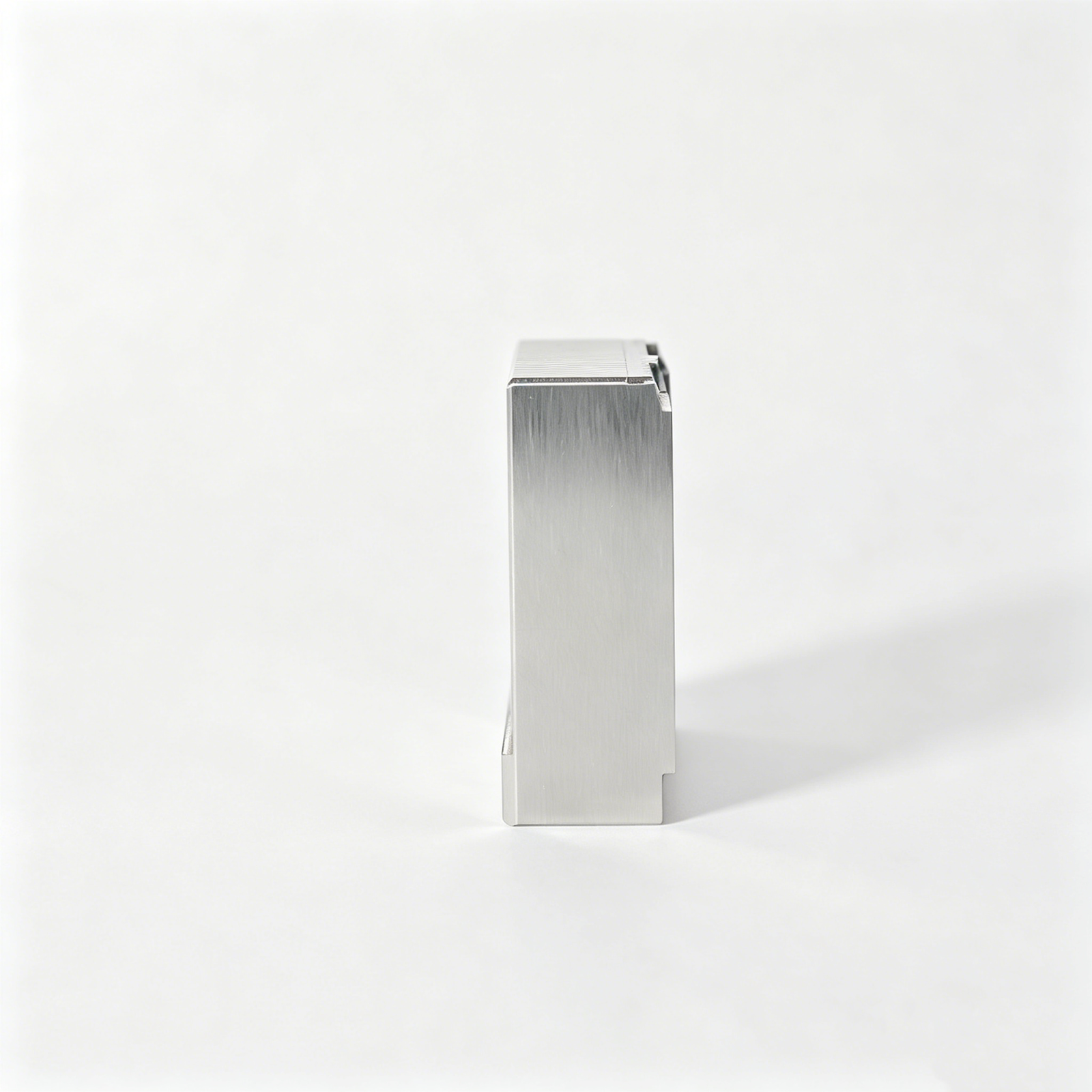
Representative Injection Mold Insert Components




Request a Quote for Related Injection Mold Insert Components










Injection Mold Inserts: Engineering Advantages
A disciplined workflow for turning drawings into inspectable mold components with clear technical decisions before production.
Drawing Review First
Review 2D drawings, models, materials, quantities, and application context to identify manufacturability questions before quotation or production planning begins.
Critical Dimensions Planned
Align critical-to-quality dimensions, datums, tolerance stacks, and surface priorities with practical machining access and an appropriate inspection method.
Process Route Selection
Select CNC machining, EDM, grinding, fitting, and finishing steps around geometry, hardness sequence, wire paths, electrode needs, and grinding stock.
Inspection Built In
Define measurement priorities and reporting expectations early, so final inspection documentation follows the drawing, revision, and verified order requirements.
Revision Control
Keep drawing revisions, technical clarifications, and production changes visible to reduce avoidable mismatches across machining, inspection, and delivery coordination.
Traceable Communication
Maintain clear project communication around technical decisions, quality expectations, delivery requirements, and evidence needed for injection mold inserts.
Configurable Precision Component Families
Drawing-driven process routes for mold, connector and custom components, reviewed around critical dimensions, materials, inspection requirements and production constraints.

CNC Machining Services
Precision CNC machining services for drawing-based custom parts and mold components, planned around material condition, datums, critical dimensions, tool access and inspection requirements before production commitments are made.
Upload a Drawing
CNC Milling
Custom CNC milling services for prismatic parts, inserts, plates and complex mold details. DFM review addresses clamping, cutter reach, corner radii, machining allowance and features that may require EDM or subsequent grinding.
Upload a Drawing
CNC Turning
Precision CNC turning services for rotational components such as pins, sleeves, bushings and locating features. Review focuses on concentricity, runout, shoulder geometry, thread requirements, material condition and how dimensions will be verified.
Upload a Drawing
5-Axis Machining
5-axis CNC machining supports multi-face and contoured features where fixture changes or limited tool access could affect accuracy. The process route is selected after evaluating geometry, datum relationships, cutter reach and critical surface requirements.
Upload a Drawing
Swiss & Micro Machining
Swiss machining and micro machining support small, slender and detail-intensive components where handling, deflection and measurement require careful control. Drawings are reviewed for feature scale, tolerances, material behavior and inspection practicality.
Upload a Drawing
Wire & Sinker EDM
Wire EDM and sinker EDM services address profiles, narrow slots, sharp internal geometry and hardened-tool features beyond practical cutter access. Electrode strategy, wire path, recast-layer considerations and finishing allowances are defined against drawing requirements.
Upload a Drawing
Precision Grinding
Precision surface and profile grinding is used where flatness, parallelism, profile control or fine finishing requires a controlled stock-removal stage. Grinding allowance, heat-treatment sequence, datum protection and inspection method should be agreed in advance.
Upload a Drawing
Mold Core & Cavity Inserts
Precision mold core and cavity inserts are configurable from the customer drawing and mold design. Manufacturing planning considers steel selection, heat treatment, cooling or vent features, parting surfaces, EDM access, grinding stock and critical molding interfaces.
Upload a Drawing
Ejector & Ejection Components
Ejector pins, sleeves and related ejection components are produced to drawing-defined fit, guidance and surface requirements. Review covers working length, clearance relationships, hardness condition, lubrication context, mating components and dimensional inspection needs.
Upload a Drawing
Core Pins, Guide & Locating Components
Core pins, guide pins and locating components are planned around alignment, wear interfaces and repeatable assembly. Drawing review should establish datum strategy, fit class, straightness or concentricity priorities, material and heat-treatment requirements.
Upload a Drawing
Slides, Lifters, Gates & Mold Accessories
Mold slides, lifters, gates and accessories are manufactured as configurable components rather than stock items. Process planning evaluates travel interfaces, shutoff geometry, sliding contact, clearance, wear treatment, assembly fitting and inspection of functional dimensions.
Upload a Drawing
Connector Mold Components
Precision connector mold components support high-density, alignment-sensitive tooling features. Review concentrates on fine pitch geometry, pin or cavity relationships, material and hardness requirements, EDM strategy, polishing needs and measurement access.
Upload a Drawing
Stamping Die Components
Precision stamping die components are made from drawing-defined geometry for cutting, forming, guiding and locating functions. Manufacturing planning considers working edges, clearance relationships, material and heat-treatment sequence, grinding stock and assembly interfaces.
Upload a Drawing
Injection, MIM, CIM & Overmolding Tooling
Injection, MIM, CIM and overmolding tooling components are evaluated within verified production scope. The review addresses feed and gate features, shrinkage-related design inputs, molding interfaces, material condition, machining route and inspection requirements.
Upload a Drawing
Machining Materials
CNC machining materials are selected against the drawing, functional environment and processing route. Buyers should identify specified grade, material condition, traceability needs, heat-treatment requirements and any properties that influence machining, EDM or grinding.
Upload a Drawing
Surface Finishes & Heat Treatment
Surface finishing and heat treatment are specified by functional requirement, not assumed. Review should clarify finish target, corrosion or wear need, hardness range, sequence relative to machining and grinding, masking needs and acceptance criteria.
Upload a Drawing
Quality, Metrology & Documentation
Precision inspection, metrology and quality documentation are aligned to critical dimensions, datums and the agreed inspection plan. Required reports, measurement methods, revision status, material documentation and traceability should be defined with the RFQ.
Upload a Drawing
Prototyping & Low-Volume Production
Rapid prototyping and low-volume manufacturing are managed from the same drawing and revision controls used for production components. Quantity, target date, material, critical features, inspection scope and expected follow-on demand guide the proposed process route.
Upload a DrawingMaterials for Injection Mold Inserts

Pre-Hardened Tool Steel
Often considered for general-purpose cavity and core insert work where balanced machinability and service hardness are needed. Final grade, hardness range, polish requirement, and corrosion exposure should be defined in the drawing package.

Through-Hardened Tool Steel
Used when injection mold inserts require higher wear resistance for repeated contact, sliding features, or abrasive resin conditions. Machining allowance, heat-treatment sequence, distortion risk, and final grinding stock require review before production.

Corrosion-Resistant Tool Steel
Considered for molds exposed to humid processing conditions, corrosive resin systems, or storage environments requiring improved rust resistance. Material grade, heat treatment, surface finish, and any polish-critical cavity surfaces must be confirmed.

High-Wear Tool Steel
Suitable for insert areas facing concentrated abrasion, gate wear, glass-filled material flow, or frequent mechanical contact. The required hardness, toughness, EDM strategy, and finishing route depend on geometry and the stated molding application.

Copper Alloy Inserts
Applied where localized thermal management may be part of the mold design, such as around heat-sensitive geometry or cooling-limited regions. Alloy selection, strength needs, fastening details, and interface tolerances require drawing-based engineering review.
Machining Processes for Injection Mold Inserts

CNC Milling
Milling creates cavities, profiles, pockets, and accessible three-dimensional features in injection mold inserts. Tool access, corner radii, stock condition, and datum setup are reviewed before selecting the machining sequence.

CNC Turning
Turning supports concentric diameters, shoulders, bores, and rotational features on round inserts, core pins, and locating components. The route is chosen when axial geometry and runout relationships are critical to mating performance.

Wire EDM
Wire EDM cuts accurate through-features, narrow slots, sharp internal profiles, and hardened workpieces where milling access is limited. Wire path, start-hole location, corner requirements, and finish-pass needs should be defined on the drawing.

Sinker EDM
Sinker EDM forms deep ribs, blind corners, detailed cavities, and other enclosed geometry that conventional cutters cannot reach. Electrode design, flushing, burn allowance, and surface requirements guide the planned EDM strategy.


Fitting Inspection
Fitting and inspection confirm functional relationships between injection mold inserts and mating components. Measurements follow the agreed drawing revision and inspection plan, with attention to critical dimensions, contact areas, and required reporting.
Injection Mold Inserts and Compatible Mold Hardware

Guide Pins
Guide pins support repeatable mold-half alignment and are specified by drawing-defined diameter, fit, hardness condition, and working length. Coordinate mating bushings, lubrication provisions, and datum relationships during project review.

Locating Elements
Locating elements establish controlled position between inserts, cavities, slides, or fixture interfaces. Provide the functional datum scheme, engagement geometry, tolerance priorities, and mating-part information so SUUXIANG can assess machining and inspection access.

Ejector Components
Ejector pins, sleeves, and related ejection parts are considered where release force, clearance, and surface contact affect molded-part quality. Define the component interface, heat-treatment requirement, finish, and critical running fit for review.

Gate Features
Gate-related features can be machined into injection mold inserts when the drawing defines the gate geometry, flow direction, surface requirements, and service considerations. Tool access, EDM strategy, and polishing allowance require early confirmation.

Connector Tooling
Connector-tooling features may include precision cores, cavity details, locating interfaces, and terminal-related geometry. Share mating-part context, critical pitch dimensions, datum references, material requirements, and inspection expectations for a disciplined manufacturability review.
Injection Mold Inserts, Drawing-Driven
SUUXIANG is the public-facing brand of Dongguan SuuXiang Precision Mold Co., Ltd., established in 2010 in Chang’an Town, Dongguan, Guangdong, China. Founded by XiaoCheng Huang, the company supports international teams with drawing-driven production of precision mold components, connector tooling, die components, and custom CNC-machined parts.
For injection mold inserts and related components, our work begins with drawing review: critical dimensions, datums, material and heat-treatment requirements, machining access, EDM or grinding strategy, and inspection expectations. CNC machining, EDM, precision grinding, fitting, and inspection are planned as a controlled workflow, with revision visibility and order-matched documentation kept central to project coordination.

Deep-Dive Capabilities for Injection Mold Inserts
DFM and Datum Review
SUUXIANG reviews the drawing and available 3D model before quotation to identify critical dimensions, datum relationships, tolerance stack concerns, machining access, and material or heat-treatment dependencies. The discussion establishes what must be controlled before a process route is committed.
- Identify critical-to-quality dimensions and functional interfaces
- Confirm datum scheme before machining and inspection planning
- Review wall conditions, corner relief, and tool-access constraints
- Clarify material, heat treatment, quantity, and application requirements

CNC and EDM Strategy
Each injection mold insert requires a route that matches its geometry, tolerance priorities, and surface requirements. SUUXIANG considers CNC milling, multi-axis machining, wire EDM, sinker EDM, and electrode planning together, so inaccessible features and wire paths are resolved before production.
- Match machining method to geometry and critical features
- Review electrode needs for deep ribs, corners, and cavities
- Plan wire paths, start holes, and cut sequence where applicable
- Keep process decisions aligned with the approved drawing revision

Grinding and Fitting Allowance
Precision faces, shutoff conditions, and mating relationships often depend on controlled stock allocation rather than a single machining step. SUUXIANG evaluates grinding allowance, heat-treatment sequence, fitting requirements, and adjacent component interfaces to support a practical finishing plan for the insert.
- Allocate grinding stock for critical faces and fits
- Consider dimensional movement after heat treatment
- Review shutoffs, locating surfaces, and mating components
- Define fitting scope and acceptance criteria before release

Inspection and Revision Control
Inspection planning follows the order requirements and the features that drive mold function. SUUXIANG aligns measurement methods, reporting needs, drawing revision status, and delivery information so engineering, sourcing, and quality teams can review the same controlled production record.
- Link inspection points to critical drawing dimensions
- Confirm required reports and acceptance expectations
- Maintain visibility of approved drawing revisions
- Coordinate delivery details with the verified inspection plan

Why Choose SUUXIANG for Injection Mold Inserts
Compare a drawing-driven component workflow with quotation-only sourcing for critical mold work.
← Swipe left or right to view →
Injection Mold Inserts: Our Precision Manufacturing Process
A controlled workflow that keeps critical dimensions, process decisions, inspection expectations, and revisions visible from RFQ through delivery.
Review Drawings and RFQ
We review 2D drawings, available 3D models, material, quantity, application context, delivery target, and inspection requirements before confirming the quotation basis.
Plan Critical Process Route
The team identifies critical dimensions, datum strategy, machining access, heat-treatment sequence, EDM needs, grinding allowance, and inspection methods for the requested components.
Machine and EDM Features
CNC milling, turning, multi-axis machining, wire EDM, sinker EDM, and micro-machining are selected according to feature geometry, tool access, and drawing requirements.
Grind and Fit Components
Precision grinding and fitting address final functional surfaces, controlled stock removal, mating relationships, and assembly-sensitive details defined by the approved drawing revision.
Inspect Against Approved Plan
Inspection follows the agreed plan, focusing on critical dimensions, datums, surface requirements, and any reporting or traceability documentation specified with the order.
Pack and Coordinate Delivery
Completed injection mold inserts are packed according to component condition and shipment needs, with revision, inspection, and delivery information coordinated before dispatch.
Work With SUUXIANG on Injection Mold Inserts
Move from drawing review to inspected delivery through a defined, revision-controlled manufacturing workflow.
Submit Your Requirements
Share 2D drawings, 3D models when available, material, heat-treatment, quantity, critical dimensions, inspection needs, application context, and target delivery date.
Align DFM and Quotation
Review datums, tolerance stack, machining access, EDM or grinding requirements, finishing sequence, inspection method, and revision status before production commitments are made.
Approve First Articles
Where the project requires it, evaluate sample or first-article results against the agreed drawing, critical dimensions, surface requirements, and inspection plan.
Coordinate Production and Delivery
Proceed through the approved CNC, EDM, grinding, fitting, and inspection route while SUUXIANG maintains visible revision, documentation, and delivery coordination.
Quality Records for Injection Mold Inserts
Customer Evidence for Injection Mold Inserts
Customer testimonials and case summaries are published only after SUUXIANG verifies the customer’s approval, project scope, and documented engineering, quality, or delivery outcome.
No customer endorsement is presented for this injection mold insert page without written approval and project records that support the stated manufacturing or inspection result.
Approved case information will identify the relevant drawing-review, machining, EDM, grinding, inspection, or delivery outcome without disclosing confidential customer specifications or unsupported performance claims.
Injection Mold Inserts FAQ for RFQ Preparation
Practical guidance for aligning drawings, quality requirements, timing, and commercial details before production planning.
What files should I send for injection mold inserts?
Is there an MOQ for custom injection mold inserts?
How long do injection mold inserts take to manufacture?
Can I order samples before a production run?
What materials and heat treatments can be specified for injection mold inserts?
What inspection reports are available for injection mold inserts?
How are drawing revisions controlled during manufacturing?
How do payment, shipping, and IP protection work for a custom order?
Buyer’s Guide to Injection Mold Tool Inserts
Use this decision framework to specify injection mold inserts, compare materials and retention designs, evaluate capable suppliers, control tooling and production costs, and avoid common sourcing, DFM, and quality-validation mistakes.
1. What Are Injection Mold Tool Inserts?
Injection mold tool inserts are removable or replaceable precision components that form, locate, vent, guide, or support features within a mold. Core inserts create internal molded-part geometry; cavity inserts form external geometry. Depending on the tool design, inserts can also provide wear surfaces, shutoffs, gate details, cooling interfaces, or serviceable feature changes.
They should not be confused with insert molding. Insert molding embeds a preformed component in a molded part; mold tool inserts are components of the production mold itself. The drawing review should establish the insert’s datums, parting and shutoff relationships, molding interfaces, material condition, heat-treatment sequence, machining access, and inspection requirements.
A practical insert design defines functional geometry, mating components, steel or alloy requirement, critical dimensions, surface condition, and any fitting or assembly acceptance criteria. These inputs allow the manufacturing route to be planned around CNC machining, EDM, grinding, fitting, and inspection rather than a nominal tolerance alone.
2. Evolution of injection mold inserts
One traditional route molded the plastic body first, then added threaded hardware, contacts, or pins through separate fastening or assembly operations. That sequence can divide responsibility for alignment, retention, and inspection across more than one process.
One insert-molding cycle instead locates a preformed component in the cavity before polymer is injected around it, integrating the insert with the molded part. As loading became more repeatable through dedicated fixtures and automated handling, the tool had to control insert orientation, support, gate flow, and removal without damaging functional features.
Five application groups—connectors, electronics, automotive, medical, and industrial equipment—now commonly drive tighter requirements for positional accuracy, electrical interfaces, mechanical retention, and traceable inspection. For injection mold inserts used to create these parts, drawing review must therefore link datums and critical dimensions to the loading method, cavity support, ejection path, and measurement plan before production release.
3. Types of injection mold inserts
Six insert families cover most injection-molded assemblies. Classification should follow load, alignment, conductivity, and how the mold locates the part before resin flow.
Threaded Inserts
1. Threaded inserts provide reusable fastening. Knurls, grooves, or undercuts resist torque-out; bosses can crack when resin support or gate placement is ignored.
Pins And Shafts
2. Pins and shafts locate, hinge, or transmit motion. Plain, stepped, or cross-drilled forms serve latches; deflection or flash at locating features risks misalignment.
Stamped Contacts And Terminals

3. Stamped contacts carry electrical paths in connectors. Windows, holes, and barbs retain them; thin terminals can bend during loading or under melt-front pressure.
Bushings And Sleeves
4. Bushings and sleeves provide wear surfaces or precise bores. Flanges or knurls anchor them; inadequate core support can shift concentricity.
Reinforcement Plates
5. Reinforcement plates spread load in housings or mounts. Perforations or embossed features lock plastic; sharp edges can concentrate stress or impede flow.
Specialty Functional Inserts
6. Specialty functional inserts add sensing, shielding, heat transfer, or magnets. Purpose-built pads or tabs require polarity, cleanliness, and thermal-expansion review.
4. Materials for injection mold inserts
Material selection for injection mold inserts is a system decision, not a metal preference. Resin chemistry, service exposure, thermal expansion, electrical function, and any coating must be reviewed against the drawing.
| Material | Corrosion | Strength | Conductivity | Machinability | Magnetic / Cost |
|---|---|---|---|---|---|
| Brass | Good | Medium | Good | High | No / Medium |
| Stainless steel | High | High | Low | Medium | Some / High |
| Carbon steel | Low | High | Low | High | Yes / Low |
| Aluminum | Medium | Medium | High | High | No / Low |
| Copper alloy | Medium | Medium | High | Medium | No / High |
| Ceramic | High | High | Low | Low | No / High |
| Pre-molded plastic | Resin-dependent | Low | Low | High | No / Low |
Read The Comparison
Seven material families cover most insert decisions. Ratings are relative; confirm grade, heat treatment, and coating before release.
Match The Resin System
Two interfaces govern reliability: insert-to-resin adhesion and insert-to-mold location. Expansion mismatch can create stress, cracking, or retention loss during molding and service.
Specify Evidence Upfront
Six drawing inputs prevent generic substitutions: material grade, hardness, coating, critical dimensions, resin, and environment. Request certificates and inspection evidence appropriate to the order.
5. Customizing injection mold inserts
2D drawings should define the insert datum scheme before nominal dimensions, tolerance zones, and surface callouts are quoted. Functional details belong in the model and drawing; cosmetic requests should be separately identified.
| Customization | Primary Purpose | Drawing Evidence |
|---|---|---|
| Knurl or groove | Retention, torque resistance | Profile, datum, excluded areas |
| Hole, flat, or undercut | Location and anti-rotation | Position tolerance, fixture access |
| Finish, plating, heat treatment | Corrosion and wear behavior | Condition, coverage, inspection method |
| Marking and packaging | Traceability and automation | Content, orientation, protection |
Retention And Torque Features
Knurls, grooves, undercuts, cross-holes, and flats create mechanical engagement, but each also changes resin-flow paths and toolholding requirements.
One gate-side view should identify features exposed to melt flow, placement fixtures, and torque direction. Retention features are a recognized insert-molding design consideration: https://www.fictiv.com/articles/insert-molding-guide
Interfaces And Edge Conditions
Threads, blind holes, chamfers, and locating flats require datum-referenced dimensions, thread specification, depth limits, and acceptable burr direction.
Two mating-part views help evaluate insertion clearance, torque transfer, inspection access, and whether automated loading needs a poka-yoke orientation.
Finish, Identification, And Handoff

Heat treatment, plating, and surface finish must state the required condition and any prohibited masking areas because they affect corrosion behavior, dimensions, and verification.
One RFQ package should include 2D drawing, 3D model, material, quantity, critical dimensions, inspection report needs, revision, marking, and packaging orientation.
6. Construction and quality essentials
Two interfaces govern insert reliability: the mechanical lock to the polymer and the insert’s stability during filling. Review both against the drawing’s datums, loads, resin, and molding orientation before tooling release.
Retention And Support
Two retention features—knurls, undercuts, grooves, or cross-holes—can resist pull-out and torque better than a smooth shank. Specify the required test load or torque and the datum from which insert position is controlled.
One boss needs adequate, reasonably uniform surrounding wall and positive support against injection pressure. Unsupported slender inserts can bend; locator pins or nests should contact nonfunctional surfaces where practical.
Flow, Venting, And Flash

One gate location should let melt divide and rejoin predictably around the insert without striking a delicate pin or contact directly. Flow imbalance can shift an insert, leave weld-line weakness, or concentrate deformation.
0.01 mm-class clearances are sometimes cited for precise locating, but the approved tolerance must match the tool, resin, and process evidence. Vent paths must evacuate air; shutoffs require controlled contact to limit flash without damaging plated surfaces.
Inspection Evidence
Six inspection priorities are critical dimensions, datum-to-insert location, thread-go/no-go gauge results, burr condition, plating appearance, and specified pull-out or torque testing. Define sample quantity, acceptance criteria, and test method on the inspection plan.
One traceability record should link the part revision, material or treatment requirements, inspection result, and lot identity. Thermal-expansion mismatch between insert and resin also warrants application-specific review for cracking or retention loss.
7. Choosing an injection mold insert manufacturer
A capable supplier translates a controlled drawing into an agreed process plan, rather than quoting a nominal tolerance alone. For injection mold inserts, nomination should follow evidence review across engineering, quality, and delivery.
Drawing Review And DFM
Before nomination, ask for a marked-up drawing review identifying CTQ dimensions, datums, machining access, EDM or grinding needs, and heat-treatment sequence.
A 3D model, mating-part context, and revision history should accompany the review; unresolved assumptions must be logged before release.
- Which dimensions require CMM, microscope, or functional-gage verification?
- Where are electrode, wire path, and grinding allowances required?
- Who approves DFM changes and records the revision?
Process And Material Fit
For each part family, request the proposed CNC, EDM, grinding, fitting, and inspection route. Confirm that material sourcing, hardness requirements, and certificates can be traced to the order.
For connector or stamping-related tooling, ask how delicate features will be supported, clamped, and protected between operations.
Evidence Before Nomination
Before release, request a sample or first-article plan, dimensional report format, capacity view, and realistic lead-time milestones. Compare communication response, open-issue handling, and change-control discipline during the quotation stage.
A supplier should state constraints early, including unavailable processes, inspection gaps, or schedule risks, rather than converting assumptions into production commitments.
- Marked-up drawing and process-flow proposal
- Material and heat-treatment traceability plan
- First-article and final-inspection records
- Revision, packing, and delivery-control procedure
8. Common injection mold insert mistakes
These failures usually originate before steel is cut: an unclear functional requirement becomes a costly tool or launch change. Review retention, material behavior, handling, and inspection together during drawing review.
Retention And Thermal Mismatch
Smooth inserts can spin, pull out, or shift under molding pressure. Specify knurls, grooves, holes, or other retention geometry, plus the datum that locates it.
Resin-to-metal expansion differences can concentrate stress during cooling or service. Confirm resin, insert alloy, operating temperature, and boss geometry with the molder before release.
Unnecessary Precision And Missing Data
Over-tight tolerances raise grinding, EDM, inspection, and scrap risk without improving function. Mark critical dimensions, mating datums, and allowable noncritical variation.
Incomplete drawings leave surface finish, heat treatment, plating, burr limits, and revision status open to interpretation. Issue a controlled 2D drawing with the 3D model and acceptance criteria.
Automation And Validation Gaps
Poorly presented inserts can jam feeders, misorient in end effectors, or damage delicate features. Define presentation, orientation, packaging, and protected contact surfaces early.
First-article approval alone may miss molding-induced movement or cracking. Validate retention, location, cosmetic condition, and functional mating using production-representative resin and conditions.
Piece-Price-Only Selection
Lowest piece price can omit inspection evidence, revision control, suitable packaging, or process coordination. Compare quotations against the same drawing revision, inspection plan, material condition, and delivery scope.
9. From drawing to production launch
A controlled launch for injection mold inserts begins before machining: the buyer defines function, mating conditions, resin exposure, and program timing. SUUXIANG can use those inputs to organize drawing review, sample evidence, and revision visibility.
Define The Acceptance Baseline
1 approved 2D drawing should identify datums, critical dimensions, material, heat treatment, surface requirements, and measurement methods.
2 parties should assign ownership: the buyer owns functional acceptance criteria, while the supplier confirms manufacturability and records agreed inspection evidence.
- Specify mating-part and molded-assembly context
- Mark CTQ dimensions and cosmetic surfaces
- Name required reports and sample quantity
Review Before Cutting Steel
1 DFM review should check tool access, EDM or grinding allowances, datum accessibility, and risks of distortion after heat treatment.
1 prototype or first sample should be inspected against the agreed plan, then evaluated in the actual molded assembly for fit, retention, flash risk, and function.
- Confirm material and finish route
- Approve sample disposition in writing
- Record deviations before next build
Lock Repeat Production Controls
1 released revision must govern the drawing, model, inspection plan, packaging, and purchase order before repeat production starts.
100% change notifications should be contractually defined for material, process route, datum interpretation, inspection method, or delivery-impacting revisions; no change should proceed without buyer disposition.
- Use revision-controlled files
- Retain approved sample records
- Define notification recipients and timing
10. Injection mold insert pricing and cost
Three pricing questions should be separated before comparing quotations: what material condition is required, which dimensions are critical, and what evidence must accompany shipment. For injection mold inserts, geometry complexity, tight tolerances, EDM or grinding, threads and knurls can change both machining time and inspection scope.
Two non-part costs often decide small-run economics: dedicated fixtures or electrodes, and controlled packaging or freight for finished surfaces. Heat treatment and coating should be priced with sequence, masking, distortion allowance, and post-process verification defined on the drawing.
| Quantity tier | Principal cost drivers | Expected unit-price direction | Typical lead-time effect |
|---|---|---|---|
| Prototype or first article | Setup, fixture design, electrodes, inspection planning | Highest | Longer review and setup share |
| Low volume | Complex geometry, tolerance, secondary operations | Decreases as setup spreads | Depends on process routing |
| Repeat batch | Revision control, material lot, inspection level | Lower when process is stable | Can shorten with confirmed routing |
| Higher volume | Cycle-time reduction, packaging, freight consolidation | Usually lower; validate capacity | May require staged deliveries |
Request a Quote for Injection Mold Inserts From Your Drawing
Upload your 2D drawing, 3D model where available, material, quantity, critical dimensions, inspection requirements, and target delivery date for review.