
CIM Tooling Components, Built From Your Drawing
Move from drawing review to inspected CNC parts, precision mold components, and CIM tooling components with disciplined DFM, machining, EDM, grinding, and quality planning.
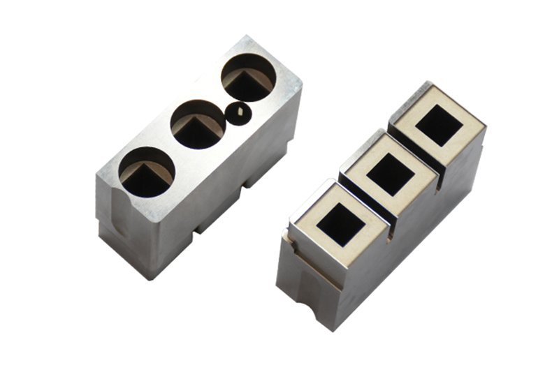
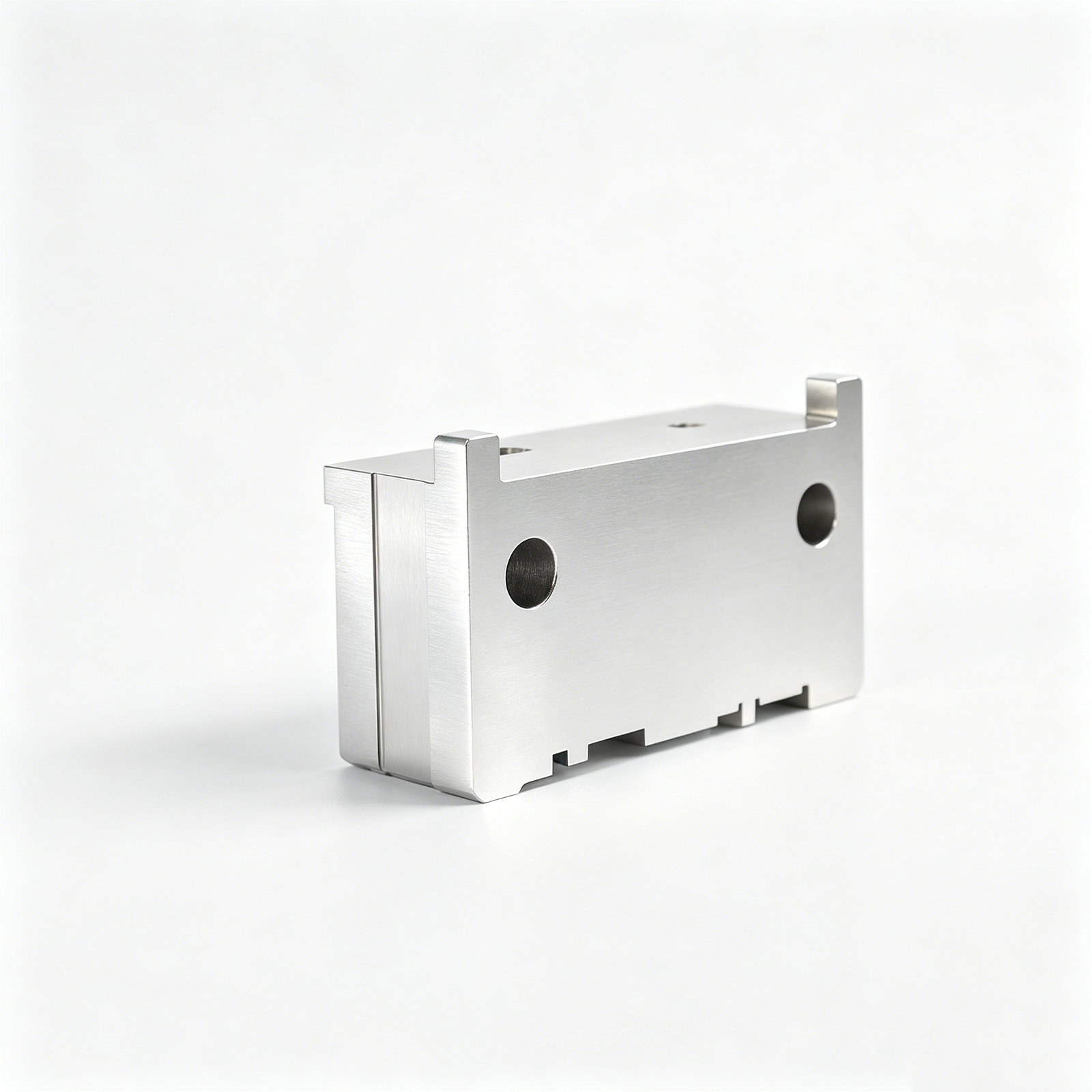
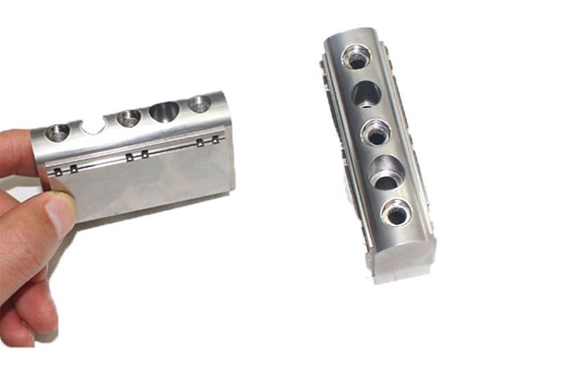
Representative CIM Tooling Components




Related Drawing-Based Parts and RFQ Options




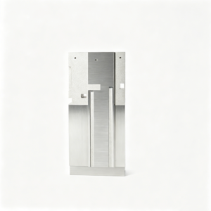





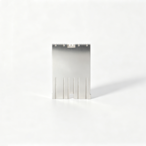
CIM Tooling Components, Planned Around Critical Details
A disciplined drawing-to-inspection workflow for complex tooling parts, with manufacturability, process decisions, and revision status kept visible.
Drawing-Based DFM Review
We review geometry, datums, tolerances, tool access, and material requirements before quotation so manufacturability questions are addressed early.
Process-Route Planning
CNC machining, EDM, grinding, fitting, and inspection are considered together to align each operation with feature requirements.
Critical-Dimension Focus
Critical-to-quality features, tolerance stacks, surface requirements, and datum relationships guide machining strategy and measurement planning throughout the project.
EDM and Grinding Strategy
Electrode needs, wire paths, heat-treatment sequence, and grinding stock are reviewed where fine features or hardened surfaces demand control.
Inspection Plan Alignment
Inspection methods and reporting expectations are defined against the drawing, helping final documentation match the agreed order requirements.
Revision Visibility
Drawing revisions, production information, and delivery coordination remain visible, supporting traceable communication from technical review through final inspection.
CIM Tooling and Configurable Part Families
Explore process routes and component families reviewed against drawings, critical dimensions, material requirements, inspection needs, and production constraints before commitment.

CNC Machining Services
Precision CNC machining services for drawing-based custom parts, planned around material, datums, critical dimensions, tool access, surface requirements, and the inspection evidence required for the order.
Upload a Drawing
CNC Milling
Custom CNC milling services for prismatic, plate, insert, and complex-profile components. Review focuses on feature access, clamping strategy, machining allowance, internal-corner limits, and dimensions that require controlled inspection.
Upload a Drawing
CNC Turning
Precision CNC turning services for shafts, sleeves, pins, bushings, and rotational parts. Diameter relationships, concentricity, runout, thread details, surface requirements, and post-heat-treatment finishing must be defined from the drawing.
Upload a Drawing
5-Axis Machining
5-axis CNC machining supports multi-face features, compound angles, and contoured geometry where fewer setups can protect datum relationships. Feasibility depends on part geometry, reach, clamping access, material condition, and inspection strategy.
Upload a Drawing
Swiss & Micro Machining
Swiss machining and micro machining support small-diameter, slender, and detail-intensive components such as pins, sleeves, and miniature connector-tooling parts. Review addresses feature stability, tolerances, deburring, material condition, and measurement access.
Upload a Drawing
Wire & Sinker EDM
Wire EDM and sinker EDM services address hardened materials, fine profiles, narrow slots, deep features, and geometry beyond conventional cutter access. Electrode strategy, wire path, corner conditions, recast-layer considerations, and finishing requirements are reviewed upfront.
Upload a Drawing
Precision Grinding
Precision surface and profile grinding is applied where flatness, parallelism, profile control, or post-heat-treatment size correction is required. Grinding stock, datum sequence, wheel access, and final measurement criteria should be defined before machining.
Upload a Drawing
Mold Core & Cavity Inserts
Precision mold core inserts and mold cavity inserts are produced from customer drawings for injection mold component and related tooling applications. Manufacturing planning considers parting features, cooling or detail access, heat-treatment sequence, EDM requirements, fitting interfaces, and critical dimensions.
Upload a Drawing
Ejector & Ejection Components
Ejector pins, sleeves, and ejection components are configured to the drawing and mold function rather than offered as assumed stock items. Diameter fit, bearing length, tip geometry, hardness requirements, surface condition, and mating-part relationships require review.
Upload a Drawing
Core Pins, Guide & Locating Components
Core pins, guide pins, and locating components support repeatable alignment and controlled mold movement. SUUXIANG reviews fit class, datum references, engagement length, wear surfaces, material and heat-treatment requirements, and inspection points before production.
Upload a Drawing
Slides, Lifters, Gates & Mold Accessories
Mold slides, lifters, gates, and accessories are made as drawing-defined tooling components. Geometry review should address travel interfaces, clearance, shutoff conditions, fitting allowances, wear areas, lubrication provisions, and the dimensions governing mold function.
Upload a Drawing
Connector Mold Components
Precision connector mold components support fine-pitch and interface-sensitive tooling work. Production planning considers pin or cavity geometry, positional relationships, material condition, EDM or grinding needs, mating features, and inspection methods appropriate to the drawing.
Upload a Drawing
Stamping Die Components
Precision stamping die components include drawing-based punches, dies, inserts, guide elements, and related wear parts. Critical review covers cutting geometry, clearance relationships, material and heat-treatment sequence, grinding stock, surface condition, and fitting requirements.
Upload a Drawing
Injection, MIM, CIM & Overmolding Tooling
Injection, MIM, CIM, and overmolding tooling components are evaluated within verified production scope. Drawing review examines feed or gate features, parting and shutoff geometry, material behavior, finish needs, mold interfaces, and required inspection evidence.
Upload a Drawing
Machining Materials
CNC machining materials are selected against the drawing, application, hardness condition, corrosion exposure, and downstream processes. Material grade, supply condition, traceability expectations, and any substitution restrictions should accompany the RFQ.
Upload a Drawing
Surface Finishes & Heat Treatment
Surface finishing and heat treatment are planned as part of the manufacturing sequence, not added after quotation. Specify required process, hardness or finish target, masking or critical surfaces, dimensional effects, and any reporting or traceability expectations.
Upload a Drawing
Quality, Metrology & Documentation
Precision inspection, metrology, and quality documentation are matched to the order’s critical dimensions and agreed inspection plan. Define datum references, measurement method, sampling needs, report format, revision level, and material or process documentation before release.
Upload a Drawing
Prototyping & Low-Volume Production
Rapid prototyping and low-volume manufacturing support engineering validation, tooling development, and controlled production needs. Submit the drawing, model when available, material, quantity, delivery target, dimensional priorities, and inspection requirements for a practical review.
Upload a DrawingMaterials for CIM Tooling Components

Tool Steel
Common for mold cores, cavity inserts, slides, and wear-critical tooling. Grade selection, heat-treatment sequence, machining allowance, EDM strategy, and final grinding requirements should be reviewed against hardness, load, and surface needs.

Stainless Steel
Used where corrosion resistance, cleanliness, or moisture exposure matters in tooling and precision components. Specific grade, heat treatment, passivation needs, machining access, and surface-finish priorities require confirmation from the drawing and application context.

Alloy Steel
Suitable for guide, locating, structural, and die-component applications requiring balanced strength and machinability. Confirm the exact grade, heat-treatment condition, critical fits, grinding stock, and inspection method before finalizing the manufacturing route.

Aluminum Alloys
A practical option for lightweight fixtures, prototype tooling, and components where rapid machining is valuable. Alloy selection should consider stiffness, wear exposure, anodizing requirements, thread strength, and dimensional stability during drawing review.

Copper Alloys
Applied when thermal conductivity, electrical performance, or EDM electrode behavior influences the tooling design. Confirm alloy grade, electrode geometry, wear allowance, surface condition, and any mating-material considerations before machining begins.
CIM Tooling Components: Machining and Finishing Routes

CNC Milling
Mills prismatic forms, pockets, contours and locating features with tool access reviewed early. Multi-axis strategies may reduce setups while protecting datum relationships and leaving suitable stock for finishing.

CNC Turning
Turns concentric diameters, shoulders, threads and axial features for pins, sleeves and cylindrical tooling parts. The route is assessed against runout, workholding, wall rigidity and mating-feature requirements.

Wire EDM
Cuts intricate profiles, narrow slots, sharp internal geometry and hardened workpieces without conventional cutting forces. Wire path, start-hole access, corner conditions and datum strategy are reviewed against the required profile.

Sinker EDM
Forms deep cavities, detailed internal features and difficult-to-reach geometry using a planned electrode strategy. Electrode wear, flushing, corner detail and subsequent finishing needs are considered before machining.


Fitting and Inspection
Confirms functional interfaces through controlled fitting and inspection of critical dimensions. Assembly context, mating parts, clearance intent and documentation requirements help define the appropriate verification plan.
Applied Accessories for CIM Tooling Components

Guide Elements
Guide pins, bushings, and alignment elements support repeatable mold or die movement. Specify datum relationships, fit requirements, lubrication provisions, and mating-part details so the selected configuration supports the intended assembly.

Ejector Hardware
Ejector pins, sleeves, retainers, and related hardware are applied where controlled part release is required. Drawing review should confirm clearance, head retention, travel, surface condition, and interaction with cores or inserts.

Die Springs
Compression springs can support return, preload, or controlled movement within tooling assemblies. Define installed height, working travel, load expectations, available space, and service conditions before a spring arrangement is evaluated.

Assembly Fasteners
Screws, dowel pins, and retaining hardware secure plates, inserts, and replaceable elements. Call out thread standards, engagement, counterbore geometry, tightening access, and locating relationships to avoid assembly conflicts.

Locating Components
Stops, keys, locating pins, and wear interfaces establish repeatable position between tooling elements. Their dimensions should relate to functional datums, tolerance stack, assembly sequence, and any intended replacement or adjustment procedure.

Identification Options
Part marks, cavity identifiers, revision labels, and traceability features help distinguish interchangeable tooling components. Provide marking location, method preference, readable orientation, and any restrictions that protect critical surfaces or fits.
About SUUXIANG Precision Manufacturing
SUUXIANG is the sole public-facing brand of Dongguan SuuXiang Precision Mold Co., Ltd., established in 2010 in Chang’an Town, Dongguan, Guangdong, China. XiaoCheng Huang is the company’s founder and legal representative. We help international teams turn drawings, models, and specifications into inspected custom CNC parts, precision mold components, connector tooling, and stamping-die components.
Our work combines DFM review with CNC milling and turning, multi-axis machining, wire EDM, sinker EDM, precision grinding, fitting, and inspection. For CIM tooling components, process planning begins with critical dimensions, datums, material requirements, machining access, EDM strategy, grinding allowance, and the inspection evidence required for the order.
What distinguishes SUUXIANG is disciplined technical coordination from RFQ through delivery. We review revisions, clarify manufacturing risks before commitments, and align final documentation with the verified inspection plan. Send the drawing, quantity, material, quality requirements, and target date so the appropriate manufacturing route can be assessed.

CIM Tooling Components: Critical Feature Control
DFM Before Process Commitment
SUUXIANG reviews drawings, models, material requirements and application context before committing to a process route. The discussion identifies critical dimensions, datum relationships, machining access, tolerance stack risks and inspection expectations so quotations reflect the actual tooling requirement.
- Confirm critical-to-quality dimensions and functional datums
- Review tool access, wall geometry and feature sequence
- Separate drawing assumptions from project-specific requirements
- Align material, heat treatment and quantity before production

EDM Strategy for Difficult Geometry
For CIM tooling components with sharp internal details, narrow slots or hardened-feature requirements, SUUXIANG evaluates whether wire EDM or sinker EDM is appropriate. Electrode design, wire path, flushing access, recast-layer considerations and downstream finishing are reviewed against the approved drawing.
- Evaluate wire EDM versus sinker EDM by feature geometry
- Plan electrode access and reference surfaces
- Consider EDM sequence alongside heat treatment
- Define finishing and inspection needs for critical EDM features

Grinding and Fitting Control
Precision grinding and fitting are planned where mating surfaces, locating features or functional clearances require controlled finishing. SUUXIANG reviews grinding stock, datum transfer and assembly relationships so CNC, EDM and grinding operations support the intended fit rather than create avoidable rework.
- Reserve practical grinding allowance on finished surfaces
- Maintain datum logic across machining operations
- Review mating interfaces and clearance-critical features
- Use fitting only within the documented project requirement

Inspection and Revision Visibility
Inspection planning for CIM tooling components begins with the order’s critical features and agreed reporting needs. SUUXIANG keeps drawing revisions, dimensional priorities and delivery information visible through the project, with final documentation matched to the verified inspection plan and purchase requirement.
- Identify inspection methods for critical dimensions
- Control drawing revisions before machining release
- Align reporting scope with the purchase requirement
- Match final documentation to the verified inspection plan

Why Choose SUUXIANG for CIM Tooling Components
A drawing-led workflow for critical features, process decisions, inspection alignment, and revision visibility.
← Swipe left or right to view →
CIM Tooling Components: From Drawing to Inspection
A controlled workflow that aligns DFM, process planning, critical dimensions, inspection requirements, and delivery coordination before production commitments.
Review the RFQ Package
We review drawings, models, material, quantity, application context, delivery target, and requested documentation to identify missing information before quotation.
Confirm DFM and CTQs
Engineering reviews datums, tolerance stack, critical dimensions, tool access, surface requirements, and revision status to clarify manufacturability and inspection priorities.
Plan Material and Process
The route is defined around material condition, heat-treatment sequence, machining allowance, CNC operations, electrode strategy, wire paths, grinding, and fitting needs.
Machine Critical Part Features
CNC machining is coordinated with EDM, precision grinding, and fitting where required, with controlled attention to drawing revisions and critical features.
Inspect, Pack, Coordinate Delivery
Completed CIM tooling components are checked against the agreed inspection plan, documented as required, protected for shipment, and coordinated against delivery requirements.
How to Source CIM Tooling Components
Move from RFQ review to controlled manufacturing with clear technical inputs, documented decisions, and inspection expectations aligned before production begins.
Submit Your Technical Package
Provide 2D drawings, 3D models when available, material, quantity, critical dimensions, surface requirements, delivery target, and any application or mating-component context.
Review DFM and Quotation
Discuss manufacturability, datum strategy, machining access, EDM or grinding needs, heat-treatment sequence, inspection expectations, revisions, and the proposed production route before commitment.
Confirm Production Requirements
Approve the agreed drawing revision, material and quality requirements, sample approach where needed, inspection plan, and delivery details before manufacturing is released.
Proceed With Controlled Manufacturing
SUUXIANG coordinates CNC machining, EDM, grinding, fitting, and inspection according to the confirmed plan, keeping revision and delivery information visible through completion.
CIM Tooling Components: Certification and Quality Documentation Review
Customer Results and Application Cases
[PLACEHOLDER] Present three approved, attributable customer testimonials or anonymized cases only when concrete outcomes and permissions are verified; do
CIM Tooling Components FAQ
Practical answers for drawing-based sourcing, from early DFM review through inspection, shipment, and revision control.
What information should I send for a CIM tooling components quotation?
Is there a minimum order quantity for CIM tooling components?
Do you review CIM tooling components before issuing a quote?
Can I order samples before production of CIM tooling components?
What factors affect lead time for custom tooling parts?
Which materials can be considered for CIM tooling components?
Can you provide inspection reports with my order?
How are shipping, IP, and drawing revisions handled?
Complete Buyer’s Guide to cim tooling components
Use this decision framework to define requirements, evaluate DFM-led suppliers, control quality and lead-time risk, and avoid costly mistakes when sourcing precision tooling components for automated, connector, mold, stamping, and low-volume manufacturing programs.
1. What Are cim tooling components?
CIM, short for computer-integrated manufacturing, normally describes the connected CAD, CAM, production-control, and data systems that move manufacturing information through a factory; it is not a physical part. In sourcing usage, cim tooling components are the drawing-defined physical parts—cores, inserts, pins, guides, die details, fixtures, and connector-tooling elements—that enable those operations. https://sixsigmadsi.com/computer-integrated-manufacturing-cim
2D drawings and 3D models establish the geometry, datums, critical dimensions, surface requirements, and interfaces that determine whether a component locates, forms, cuts, ejects, or guides correctly. A nominally similar part can fail in service when tolerance stack, fit class, material condition, or accessible machining path differs from the approved design.
1 controlled process route links the released revision to material identification, heat-treatment sequence where specified, CNC, EDM, grinding, fitting, and the defined inspection method. That traceability lets engineering and supplier-quality teams evaluate functional risk, investigate deviations, and confirm that the delivered part matches the production release.
2. Evolution of cim tooling components
1950s-era numerical control began shifting toolroom work from manually laid-out features toward programmed machine motion, while hand fitting, grinding, and EDM remained essential for final relationships. Early drawings carried much of the process knowledge in the judgment of the toolmaker.
CAD/CAM later made the 2D drawing and 3D model a transferable manufacturing dataset: geometry could inform toolpaths, electrodes, wire paths, and revision review. Standardized mold and die elements then reduced repeated design effort, but critical fits still required datum discipline and part-specific tolerances.
Today, digitally connected cim tooling components should move with controlled revision identifiers from drawing review through machining, inspection, and production handoff. Buyers reasonably expect shorter prototype loops, repeatable replacement parts, documented measurement against critical dimensions, and a traceable record of what changed before release.
3. Types of cim tooling components
cim tooling components should be classified by the production interface they control, not merely by machining process. Each drawing must make function, datum scheme, and inspection priority explicit before routing begins.
Mold Components
Mold cores, cavity inserts, pins, slides, and lifters form or release molded features. Wear, flash, or sticking can result from unclear shutoff surfaces, parting lines, hardness sequence, and critical datums.
Stamping-Die Components
Punches, dies, stripper plates, and guide elements cut, form, or retain strip stock. Burrs, misalignment, and early breakage often trace to omitted clearances, edge condition, material, and grinding tolerances.
Connector-Tooling Parts
Connector-tooling parts locate delicate cavities, terminal features, and mating geometry. Poor positional control can create terminal mismatch; specify pin diameters, pitch datums, radii, and EDM-access constraints.
Fixtures And Jigs
Fixtures and jigs repeatably locate, clamp, or guide a workpiece during machining or assembly. Clamp distortion and setup variation require locating-point definitions, contact surfaces, load direction, and gauge references.
Automation-Interface Parts
Automation interfaces include nests, grippers, pallets, sensor brackets, and robot adapters. A missed pickup or collision can follow from unspecified mounting patterns, envelope limits, cable clearance, and repeatability-critical features.
Prototype And Low-Volume Spares
Prototype or spare parts restore trials, maintenance, or short runs without assuming production-tool economics. Revision errors are costly; identify interchangeable interfaces, legacy dimensions, material substitutes, and required inspection records.
4. Materials for cim tooling components
Six material families cover most cim tooling components, but selection should begin with load, temperature, media and required life. Price alone misses dimensional movement after heat treatment, coating and service exposure.
| Family | Strengths | Watchpoint |
|---|---|---|
| Tool steel | Hard, wear resistant | Heat-treatment distortion |
| Stainless steel | Corrosion resistant | Lower thermal conductivity |
| Aluminum alloy | Machinable, conductive | Limited wear resistance |
| Copper alloy | High conductivity | Soft; protect edges |
| Carbide | Extreme wear resistance | Difficult machining, brittle |
| Engineering plastic | Light, insulating | Creep and low heat resistance |
Match Material To Service
Tool steels suit high contact stress and wear; stainless steels suit humid, corrosive or cleanliness-sensitive service. Aluminum and copper alloys favor rapid heat transfer or low-load prototype tooling, while carbide targets severe localized wear.
Plan The Process Route
Heat treatment can change hardness and dimensions, so leave grinding stock and define datums before hardening. Coatings add thickness and may alter fit, edge break requirements and inspection limits.
- Specify hardness range and heat-treatment sequence.
- Reserve EDM and grinding allowance.
- State coating thickness and mating clearance.
Verify Stability And Evidence
Engineering plastics are appropriate for fixtures, insulation or low-load guides, not unreviewed high-wear duty. SUUXIANG should review material certification, critical dimensions and the inspection plan against the drawing before release.
5. Customization for cim tooling components
Each cim tooling components drawing can define size, fit, finish, identification, and assembly relationships. SUUXIANG should review these requirements against the functional application before committing a process route.
| Requirement | Specify | Avoid |
|---|---|---|
| Dimensions | Functional datum scheme | Chain dimensions |
| Tolerance | CTQ feature and method | Blanket tight tolerances |
| Finish | Ra, texture, or coating | Unstated cosmetic expectations |
| Identification | Location and marking method | Marks on sealing faces |
Define Functional Datums
Primary, secondary, and tertiary datums should reflect how the part locates in its mold or fixture.
Critical-to-quality features should be tied to those datums, not independently tightened across every surface.
- Identify mating faces and locating pins
- State runout, position, or profile where functional
- Separate reference dimensions from inspection dimensions
Control Requirements By Function
Threads, EDM details, ground faces, coatings, heat treatment, and engraving need explicit callouts.
Cosmetic surfaces should have separate acceptance criteria so appearance requirements do not constrain functional machining unnecessarily.
Release Matched Assemblies
Matched inserts, slides, and pins require mating-condition notes, clearance intent, and assembly identifiers.
Revision-controlled 2D drawings and models should name the governing revision before production release.
6. Construction Quality Elements
Before release, cim tooling components need a quality plan tied to functional datums, not a general tolerance note. The drawing should identify acceptance features, process-sensitive conditions, and the evidence required with the shipment.
Datums And Functional Geometry
Primary, secondary, and tertiary datums should reflect how the component locates in its mating tool. Stack-up review must link hole position, concentricity, flatness, and critical interfaces to those datum references.
- Define the functional locating faces
- Separate profile from size requirements
- State allowed edge-break limits
Process Effects And Finishing
Heat treatment can distort thin sections and precision bores, so stock, sequence, and post-treatment grinding require agreement. Coating buildup, burr removal, surface finish, cleanliness, and protected contact faces should be specified before routing.
- Nominate finish measurement direction
- Prevent burrs at ports and threads
- Define cleaning and packaging protection
Inspection Method Fit
CMM inspection suits datum-related position and form verification; dedicated gauges suit repeated functional checks. Optical checks can assess small edges or features, while material certificates and hardness verification should match the ordered specification.
- CMM for positional relationships
- Gauges for fit-critical features
- Optical checks for small details
- Verify material and hardness evidence
7. Choosing a cim tooling components Manufacturer
SUUXIANG should be evaluated through the evidence returned against a 2D drawing, 3D model, and stated CTQs. A quotation alone does not show whether a supplier can control the proposed process route.
| Order Phase | Supplier Evidence | Buyer Question |
|---|---|---|
| Prototype | DFM and first article | What risks remain? |
| Bridge | Capacity and inspection plan | What changes at volume? |
| Repeat | Traceability and corrective action | How are revisions contained? |
Review The DFM Response
Within the first drawing review, ask for datum interpretation, machining access concerns, EDM or grinding allowances, and unresolved tolerances.
A useful response identifies assumptions and proposes choices; it does not silently substitute material, finish, or inspection method.
- Which dimensions are CTQs?
- Which features require EDM or grinding?
- What assumptions need written approval?
Verify Production Evidence
For prototype, bridge, or repeat orders, define the first-article trigger and report format before release.
Request material identity, heat-treatment records when specified, dimensional results tied to drawing revisions, and nonconformance handling.
- First-article acceptance criteria
- Inspection equipment and sampling
- Material and revision traceability
- Corrective-action response path
Confirm Delivery Control
Before a repeat order, confirm available capacity against the required quantity and delivery window. Ask how parts are protected, labeled, separated by revision, and communicated through shipment.
- Capacity fit by order phase
- Revision-controlled labels
- Feature-protective packaging
8. Common cim tooling components Mistakes
Eight recurring RFQ errors create avoidable rework in cim tooling components: undefined geometry, unsuitable process assumptions, and mismatched commercial scope. Resolve each before release through a drawing review tied to inspection and production evidence.
Define Datums And Interfaces
Two drawings can show identical dimensions yet produce different parts when datum references are absent. Identify primary, secondary, and tertiary datums, plus every mating interface.
Ask: Which surfaces locate this part in the mold or assembly? Prevention: provide section views, mating-part details, and functional clearance targets.
Specify Material By Condition
A catalog alloy name alone does not define hardness, heat-treatment state, corrosion need, or finish. State the required material condition and any approved substitution limits.
Ask: What property controls function after processing? Prevention: review dimensional change and grinding allowance after heat treatment or coating.
Apply Tolerances Functionally
A tight tolerance on every feature raises machining and inspection effort without improving fit. Mark critical dimensions, surface requirements, and measurement method separately from general tolerances.
Ask: Which dimension changes performance? Prevention: confirm tool access and measurement feasibility before quoting.
Align Prototype And Quote Scope
One acceptable prototype does not establish a stable production route, inspection plan, or revision-control method. Compare quotations only after quantities, documents, treatments, inspection, packaging, and delivery terms match.
Ask: What evidence is included at each build stage? Prevention: request a scope matrix and production-release review.
9. From Drawing to Production Release
A production release begins when design, manufacturing, quality, and procurement share the same controlled requirements. For cim tooling components, treat each handoff as an evidence check, not an informal approval.
Define The Program
1. Design should state the component function, mating condition, annual and release quantity, material, hardness, and critical datums.
2. Procurement should provide target delivery, destination, packaging constraints, and the commercial quantity basis before quotation.
Review Drawings And DFM
3. Engineering should issue a revision-marked 2D drawing with tolerances, surface requirements, and a 3D model where available.
4. Manufacturing should return DFM feedback covering tool access, EDM or grinding needs, machining allowance, and unresolved datum interpretation.
Align Release Evidence
5. The quotation should record the agreed process route, material condition, inspection scope, lead-time assumptions, and exclusions.
6. Quality should approve the first article or sample against the controlled drawing, including the measurement method for each critical feature.
Control Repeat Orders
7. Release only one revision after design, supplier, and buyer confirm the approved sample and inspection criteria.
8. Procurement should track shipment milestones, while quality records nonconformities and manufacturing incorporates approved corrective actions before repeat orders.
10. Pricing and Cost Drivers
1-piece and prototype orders usually carry the greatest programming, fixturing, CAM verification, and first-article burden per component. For cim tooling components, material availability, multi-axis access, EDM electrodes or wire paths, tight tolerances, grinding time, finishing, and inspection reporting all change the quotation.
2D drawings, 3D models, revision level, quantity, material and heat-treatment callouts, CTQ dimensions, surface requirements, and target date allow a comparable quote. Expedited service may require schedule changes; confirm feasibility and inspection scope before release.
| Quantity tier | Setup or programming impact | Unit-cost direction | Typical lead-time consideration |
|---|---|---|---|
| 1–5 pieces | Highest per part; setup dominates | Highest | Allow drawing review, first-piece inspection, and routing |
| 6–25 pieces | Setup spreads across batch | Declines | Group compatible operations where practical |
| 26–100 pieces | Dedicated fixture or inspection planning may be justified | Further declines | Plan material, heat treatment, and external finishing early |
| 100+ pieces | Validate repeatability, tooling life, and sampling plan | Quote-specific | Confirm capacity, delivery cadence, and revision control |
Upload Your CIM Tooling Components Drawing
Submit drawings, material, quantity, critical dimensions, documentation requirements, and target delivery date for a disciplined DFM and quotation review.