
Connector Insulator Mold Inserts, Reviewed Before Machining
Submit your drawing for DFM-led CNC, EDM, grinding and inspection planning for connector insulator mold inserts.
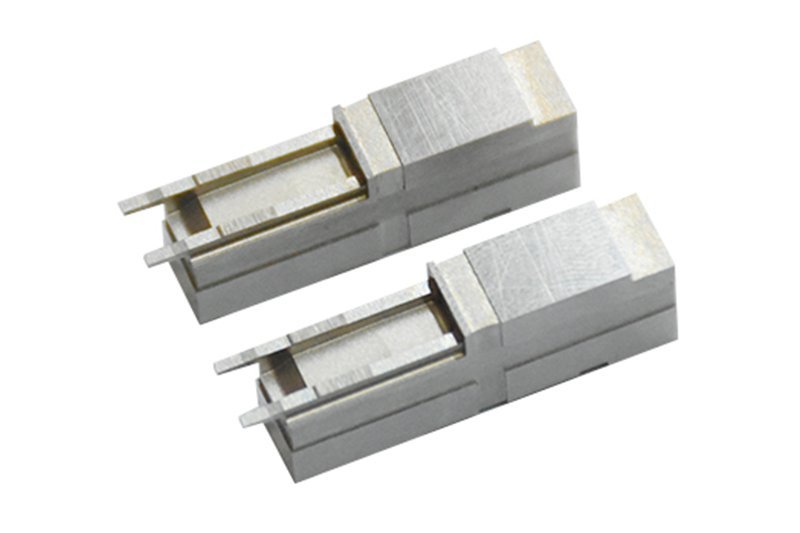
Featured Connector Insulator Mold Insert Configurations





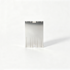
Related Configurable Tooling Components










Why Connector Insulator Mold Inserts Need a Controlled Process
Drawing-first review keeps critical connector-tooling requirements visible from DFM through inspection and delivery coordination.
Drawing Comprehension
We review 2D drawings, 3D models, datums, materials, and application context before establishing a practical manufacturing discussion.
Critical Dimension Review
Critical-to-quality dimensions, tolerance relationships, surface requirements, and mating features are identified early to guide process and inspection planning.
Process Route Planning
CNC machining, EDM, grinding, fitting, and heat-treatment sequence are considered against tool access, machining allowance, and feature geometry.
Revision Control
Drawing revisions and clarified requirements remain visible throughout coordination, helping prevent production against superseded geometry or undocumented assumptions.
Inspection Planning
Inspection methods are aligned with the drawing, critical features, datum strategy, and required reports before final documentation is prepared.
Traceable Communication
Material, quantity, quality expectations, delivery requirements, and inspection needs are documented to support clearer project decisions and handoffs.
Connector Mold Inserts and Tooling Families
Drawing-driven manufacturing categories for configurable precision parts, process planning and inspection requirements.

CNC Machining Services
Precision CNC machining services for drawing-based custom parts where datums, critical dimensions, material condition and inspection requirements must be reviewed before the production route is confirmed.
Upload a Drawing
CNC Milling
Custom CNC milling services for prismatic parts, plates, inserts and complex features. Tool access, clamping strategy, wall geometry, machining allowance and surface requirements are evaluated against the supplied drawing and model.
Upload a Drawing
CNC Turning
Precision CNC turning services for rotational parts such as pins, sleeves, bushings and locating features. Quotation review should define concentricity, runout, thread details, material condition and the dimensions requiring inspection.
Upload a Drawing
5-Axis Machining
5-axis CNC machining supports multi-face and contoured components where fewer setups can protect positional relationships. The process route depends on geometry, tool reach, fixture access, tolerance stack and the required inspection method.
Upload a Drawing
Swiss & Micro Machining
Swiss machining and micro machining address small, slender or detail-dense components that require controlled support during cutting. Drawings should identify critical diameters, transitions, threads, surface priorities and any mating-function requirements.
Upload a Drawing
Wire & Sinker EDM
Wire EDM and sinker EDM services support sharp internal geometry, narrow slots, hardened materials and features beyond conventional cutting access. Electrode strategy, wire path, corner requirements, recast-layer considerations and finishing expectations require early review.
Upload a Drawing
Precision Grinding
Precision surface and profile grinding supports controlled flatness, parallelism, profiles and finished mating surfaces. Grinding stock, heat-treatment sequence, datum references and measurement points should be defined before final finishing.
Upload a Drawing
Mold Core Inserts & Mold Cavity Inserts
Precision mold core and cavity inserts are configurable components manufactured from the approved drawing, material and heat-treatment requirements. Review focuses on parting geometry, cooling or vent features, EDM access, grinding allowance and critical molded-part surfaces.
Upload a Drawing
Ejector & Ejection Components
Ejector pins, sleeves and ejection components are reviewed for fit, sliding function, bearing lengths, clearance relationships and wear considerations. The manufacturing outcome must align with the mold’s datum scheme, material condition and inspection needs.
Upload a Drawing
Core Pins, Guide & Locating Components
Core pins, guide pins and locating components establish formed features, alignment and repeatable positioning within a mold assembly. Drawings should identify mating relationships, press or slip fits, hardness requirements and dimensions critical to interchangeability.
Upload a Drawing
Slides, Lifters, Gates & Mold Accessories
Mold slides, lifters, gates and accessories are produced as configurable tooling components for motion, release and material-flow functions. Design review considers travel geometry, interfaces, wear surfaces, machining access, EDM needs and fitting requirements.
Upload a Drawing
Connector Mold Components
Precision connector mold components support fine-pitch cavities, terminal-related features, insulator geometry and repeatable alignment. Buyers should provide application context, mating features, critical dimensions, material requirements and inspection priorities for a defensible process plan.
Upload a Drawing
Stamping Die Components
Precision stamping die components support cutting, forming, guiding and locating functions in die assemblies. Process planning considers tool-steel condition, clearance-sensitive geometry, heat-treatment sequence, grinding stock, EDM features and dimensional verification.
Upload a Drawing
Injection, MIM, CIM & Overmolding Tooling
Injection mold components and tooling for MIM, CIM, and overmolding are assessed within verified production scope. Drawings and application details should clarify material behavior, shrinkage inputs, parting requirements, insert interfaces, gate strategy, and component quality expectations.
Upload a Drawing
Machining Materials
CNC machining materials are selected from the drawing and functional requirements, including machinability, strength, corrosion resistance, wear behavior and heat-treatment compatibility. Final material acceptance depends on project-specific specification and traceability requirements.
Upload a Drawing
Surface Finishes & Heat Treatment
Surface finishing and heat treatment are planned around functional surfaces, corrosion or wear needs, dimensional change risk and post-treatment finishing. Buyers should specify finish callouts, hardness requirements, masking needs and dimensions affected by treatment.
Upload a Drawing
Quality, Metrology & Documentation
Precision inspection, metrology and quality documentation are aligned to the order’s critical dimensions, datums and reporting needs. The inspection plan should define methods, sampling or full-check expectations, record format, revision status and traceability requirements.
Upload a Drawing
Prototyping & Low-Volume Production
Rapid prototyping and low-volume manufacturing support drawing-driven validation, bridge quantities and controlled revisions. A practical RFQ identifies quantity, material, critical features, quality documentation, delivery target and any design changes expected during the program.
Upload a DrawingMaterials for Connector Insulator Mold Inserts

Pre-Hardened Tool Steel
Often considered for connector tooling components requiring a practical balance of machinability and service stability. Suitable use depends on cavity geometry, resin abrasiveness, expected production exposure, and the buyer’s specified hardness and inspection requirements.

Hardened Tool Steel
Considered for cores, cavity inserts, and wear-prone details where heat treatment, EDM strategy, grinding stock, and final dimensions must be planned together. The drawing should define critical interfaces, surface requirements, and revision-controlled acceptance criteria.

Stainless Tool Steel
May be specified for tooling exposed to moisture-sensitive environments or where corrosion resistance is an engineering priority. Material grade, heat-treatment sequence, polishing requirement, and mating-component conditions should be reviewed before the manufacturing route is confirmed.

Copper Alloy Inserts
Considered for localized thermal-management features in connector molds when the design calls for faster heat transfer near critical geometry. Insert retention, machining allowances, adjacent steel interfaces, and operating conditions require drawing-led review.

Tungsten Carbide
Used selectively for high-wear pins, punches, or fine features in demanding connector tooling. Its application depends on geometry, EDM or grinding access, brittle-feature risk, fit requirements, and the specified production and inspection conditions.
Precision Processes for Connector Insulator Mold Inserts


Wire EDM
Wire EDM produces fine profiles, narrow slots and controlled cut features where conventional tools cannot reach. Wire path, start-hole location and finish-pass requirements are reviewed to protect functional geometry.

Sinker EDM
Sinker EDM supports cavity details, internal forms and sharp-feature requirements through planned electrode strategy. Electrode wear, flushing access and subsequent finishing needs are considered before the process route is confirmed.


Component Fitting
Controlled fitting verifies how interdependent mold components assemble and move together. This step focuses on mating relationships, locating features and functional clearance while maintaining revision visibility throughout the project.

Final Inspection
Inspection is planned around critical-to-quality dimensions, datums and specified reporting needs. SUUXIANG checks finished connector insulator mold inserts against the order requirements and provides documentation consistent with the verified inspection plan.
Connector Insulator Mold Inserts: Supporting Components

Guide Pin Sets
Guide pins and matching bushings support repeatable mold-half alignment. Define the datum relationship, fit requirement, lubrication expectations, and material or heat-treatment specification so SUUXIANG can plan machining, grinding, and inspection accordingly.

Locating Components
Custom locating pins, blocks, and keys establish controlled positioning for inserts, cavities, or mating tooling elements. Share assembly datums, clearance conditions, and replacement requirements to review tolerance stack and practical machining access before production.

Ejector Parts
Ejector pins, sleeves, and related ejection components can be configured around part geometry and ejection strategy. Critical considerations include bearing lengths, clearance, surface condition, and interfaces that may require EDM, grinding, or fitting.

Gate Inserts
Gate inserts shape resin entry and must be evaluated with the connector part geometry, flow direction, and service expectations. Provide gate details, shutoff surfaces, material requirements, and revision-controlled drawings for a focused DFM discussion.

Slides and Lifters
Slides and lifters manage undercuts or side features where straight-pull tooling is insufficient. Their design review should address travel, guiding, wear interfaces, clearance, and assembly relationships before machining routes and inspection methods are confirmed.

Custom Machined Accessories
Custom stops, retainers, spacers, wear plates, and assembly aids can complement connector insulator mold inserts. Submit drawings with material, quantity, critical dimensions, surface priorities, and mating-component context to align the process plan with project needs.
About SUUXIANG Precision Manufacturing
SUUXIANG is the sole public-facing brand of Dongguan SuuXiang Precision Mold Co., Ltd., established in 2010 in Chang’an Town, Dongguan, Guangdong, China. Founder and legal representative XiaoCheng Huang leads the company. We help engineering, sourcing, and quality teams convert drawings and specifications into inspected custom CNC parts, precision mold components, connector tooling, and die components.
For connector insulator mold inserts, our work begins with DFM and critical-dimension review before quotation or production commitments. We assess datums, tolerance stack, material and heat-treatment requirements, machining access, EDM strategy, grinding allowance, inspection method, and revision status so the proposed route aligns with the drawing.
Our difference is disciplined coordination across CNC machining, EDM, grinding, fitting, and inspection. Rather than treating a drawing as a generic quotation request, SUUXIANG keeps technical questions, process decisions, inspection expectations, and delivery information visible throughout the project.

Connector Insulator Mold Inserts: Critical Tooling Controls
DFM and Datum Review
Before quotation, SUUXIANG reviews the drawing, 3D model, critical dimensions, datum scheme, material requirements, and mating context for connector insulator mold inserts. The objective is to identify manufacturing decisions early, before tool access, electrode design, or inspection planning become production risks.
- Confirm critical-to-quality dimensions and datum relationships
- Review wall conditions, shutoffs, draft, and feature accessibility
- Define machining, EDM, and grinding allowances
- Record revision status and open technical questions

CNC Access Planning
Connector tooling often combines fine pin features, narrow pockets, locating surfaces, and geometry that demands more than a standard milling route. SUUXIANG plans CNC milling, turning, multi-axis work, or micro-machining around reachable geometry, stable workholding, and the dimensions that govern final fit.
- Match cutter access to cavity, core, and insert geometry
- Plan workholding around datums and inspection references
- Identify features needing secondary EDM or grinding
- Separate roughing, semi-finishing, and finish-machining stages

EDM and Grinding Strategy
Where small internal corners, deep ribs, fine slots, hardened material, or close-fitting surfaces limit conventional cutting, the process route may require wire EDM, sinker EDM, precision grinding, and fitting. SUUXIANG evaluates electrode access, wire path, grinding stock, and sequence against the approved drawing.
- Review wire start-hole and contour access
- Plan electrode geometry for non-machinable details
- Reserve controlled grinding stock where required
- Sequence heat treatment and finishing to protect datums

Inspection and Revision Control
Inspection planning for connector insulator mold inserts begins with the dimensions that affect insert position, contact alignment, parting performance, and interchangeability. SUUXIANG aligns measurement methods and reporting expectations to the order, while keeping drawing revisions and delivery information visible throughout the project.
- Define practical measurement methods for critical features
- Align inspection records with the verified order requirements
- Control drawing, model, and change-revision status
- Escalate dimensional or process questions before release

Why Engineering Teams Choose SUUXIANG for Connector Insulator Mold Inserts
Compare SUUXIANG’s drawing-first review and process planning with a typical quote-only sourcing path before committing connector tooling decisions.
← Swipe left or right to view →
Connector Insulator Mold Inserts: From Drawing to Inspection
A drawing-first workflow that keeps DFM decisions, critical dimensions, process routing, inspection requirements, and revision status visible before delivery coordination.
Review RFQ Package
We review the 2D drawing, available 3D model, material, quantity, application context, delivery target, and requested inspection documentation before committing to a process route.
Confirm DFM Priorities
Project discussion identifies critical dimensions, datums, tolerance stack risks, surface requirements, machining access, heat-treatment sequence, and the appropriate EDM or grinding strategy.
Machine Core Features
CNC milling, turning, multi-axis work, and micro-machining are selected as applicable to establish insert geometry, stock allowances, reference surfaces, and accessible detail features.
Finish EDM And Grinding
Wire EDM, sinker EDM, and precision grinding address fine profiles, narrow features, hardened details, and final functional surfaces according to the approved drawing and process plan.
Fit Inspect Coordinate Delivery
Components are fitted where required, inspected against the agreed plan, and coordinated with revision-controlled records and delivery information matching the confirmed order requirements.
How to Work With SUUXIANG on Connector Insulator Mold Inserts
Move from a controlled drawing review to documented production coordination with requirements visible at each decision point.
Submit Your Drawing Package
Provide 2D drawings, available 3D models, material, quantity, application context, target date, and inspection requirements for connector insulator mold inserts.
Clarify Critical Requirements
Review datums, critical dimensions, surface requirements, heat-treatment sequence, machining access, EDM needs, grinding stock, and mating-component interfaces before process commitments.
Confirm the Production Route
Discuss DFM findings, feasible process routing, inspection approach, quotation details, and sampling needs so technical assumptions are agreed before production begins.
Coordinate Manufacturing and Inspection
Follow revision-controlled coordination through CNC machining, EDM, grinding, fitting, and inspection, with questions escalated when the drawing or manufacturing route requires clarification.
Review Final Documentation
Receive order-matched inspection documentation and delivery information aligned with the verified inspection plan, supporting traceable handoff for your connector tooling project.
Customer Outcomes: Case Studies Pending Verification
Connector Insulator Mold Insert RFQ FAQs
Customer feedback will be published after written approval and verification of the drawing revision, inspection scope, quantity, and measured project outcome.
This case-study slot is reserved for a verified connector-tooling project, including the documented process route, critical dimensions, and confirmed delivery or quality result.
A future customer testimonial may describe a specific outcome only when SUUXIANG has approval to publish the customer name, application context, and supporting project evidence.
Complete Buyer’s Guide to Connector Insulator Mold Inserts
Prepare a clearer drawing package, align inspection needs early, and request a project-specific review before production commitments.
What should I include when requesting connector insulator mold inserts?
Can SUUXIANG review my connector insulator mold inserts drawing before quotation?
What materials can be specified for connector insulator mold inserts?
Is there a minimum order quantity for custom connector tooling components?
How long do connector insulator mold inserts take to manufacture?
Can I request samples or first-article inspection before a larger order?
What inspection report can I request for connector insulator mold inserts?
How are payment, shipping, and intellectual property handled for an RFQ?
Complete Buyer’s Guide to connector insulator mold inserts
Use this decision framework to specify connector insulator mold inserts, compare tooling and material choices, evaluate capable suppliers, control validation risk, and avoid drawing, tolerance, and costing mistakes before production.
1. What Are connector insulator mold inserts?
One connector insulator mold insert is a precision-made portion of the production mold that creates dielectric polymer geometry: pin passages, polarization keys, contact-retention features, and mating faces. It is a tooling component, not the molded connector insulator that leaves the press; connector insulators commonly contain through-holes, alignment, keying, and retention features (https://www.activemolding.com/blog/micro-molded-insulators-connectors-engineering-guide).
Two material systems must remain distinct in the drawing review. The finished insulator is the molded nonconductive polymer body, while contacts or pins are conductive metal parts that may later be assembled or molded in; insert molding can encapsulate metal inserts with plastic (https://www.newayprecision.com/study-cases/insert-molding-for-electrical-connector-ensuring-reliability-and-performance).
Three functional dimension groups should be assigned to the insert: passage location and size relative to datums, retention-form geometry, and mating/keying position. Buyers should identify which of those dimensions must remain reliable after molding shrinkage, wear, and any assembly relationship, then state the inspection method and revision-controlled acceptance criteria in the RFQ.
2. Why Connector Tooling Became More Demanding
At 2.54 mm pitch, a small hole-location error may be manageable; at 0.635 mm pitch, the same error consumes far more of the available positional margin. Industry discussion of micro-molded connectors identifies the shift from 2.54 mm to 1.27 mm, 0.635 mm, and below as a key reason tooling precision has tightened: https://www.activemolding.com/blog/micro-molded-insulators-connectors-engineering-guide
At 50, 100, or 200-plus contact positions, each added cavity feature increases the need to control pin straightness, insert alignment, and the datum relationship between holes, keying, and retention geometry. Complex through-holes also make core-pin stiffness and support a tooling issue, because injection pressure can deflect slender pins.
Five linked tooling decisions—alignment, venting, cooling, ejection, and service access—should therefore be reviewed together for connector insulator mold inserts. Vent locations must release air without flashing critical features; cooling must be balanced around dense pin fields; and replaceable wear items should be accessible without disturbing established cavity-to-core alignment.
3. Types of connector insulator mold inserts
Connector insulator mold inserts are best classified by the feature they create and the service action they permit. A drawing’s pin count, undercuts, wear zones, and molded-in metal usually reveal the required configuration.
| Type | Forms | Service And Design Choice |
|---|---|---|
| Cavity | Exterior keys, walls | Split for repairable local detail |
| Core | Bores, pockets | Monolithic for shared datums |
| Pin array | Contact passages | Replace bent or worn pins |
| Wear insert | Gates, shutoffs | Modular replacement limits repair |
| Slide or lifter | Undercuts, side holes | Modular moving wear surfaces |
| Insert fixture | Terminal location | Modular for format changes |
Forming Inserts
Cavity inserts form exterior walls, keys, and latch geometry; core inserts form bores, pockets, and internal retention details. Use monolithic blocks when datum continuity dominates; split inserts when polishing, EDM repair, or local replacement is expected.
Pin And Wear Modules
Multi-pin arrays create contact passages, while interchangeable wear inserts protect gates, shutoffs, and abrasion-prone details. Pin bending and flash risk increase with unsupported length; modular retention enables replacement without rebuilding the main block.
Moving And Insert Fixtures
Slide or lifter inserts release side holes and undercuts; insert-molding fixtures locate terminals before resin encapsulation. Choose modular moving elements for recurring wear or setup changes, but keep a stable datum structure monolithic where positional stack-up is critical.
4. Materials for connector insulator mold inserts
Connector insulator mold inserts are tool components, not the insulating resin. Select steel or carbide against resin chemistry, glass loading, thermal demand, geometry, and planned repair route.
| Insert material | Best use | Tradeoff | Inspection concern |
|---|---|---|---|
| H13 | Tough, repairable cores | Moderate wear | Heat-treatment distortion |
| S136 stainless | Corrosive resin, polished cavities | Higher cost | Corrosion and surface finish |
| D2 or high-wear steel | Glass-filled resin | Lower toughness | Edge chipping |
| Carbide | Micro pins, severe abrasion | Brittle; difficult repair | Cracks and pin runout |
Material Selection Matrix
Four common choices require different inspection priorities.
Resin Drives Wear
Glass-filled resin abrades gates, pin bores, and shutoffs; favor wear-resistant grades or carbide locally.
High-temperature PEEK, PPS, or LCP raises thermal and polishing demands; confirm the resin grade and molding window.
Repair Before Release
H13 supports robust welding and re-machining; carbide usually needs replacement rather than weld repair.
Inspection should target pin diameter, positional datums, shutoff damage, and polished surfaces after each intervention.
5. DFM for connector insulator mold inserts
2D drawings for connector insulator mold inserts should be reviewed as a molding system, not isolated steel geometry. Resin shrinkage, core-pin deflection, cooling, and ejection can each move functional features.
Pin Geometry And Datums
Pin pitch, hole diameter, and hole depth need a common datum and an explicit functional measurement condition. 3D models should identify contact entry, alignment features, minimum wall thickness, draft direction, and radii before core pins or EDM details are released.
Steel And Flow Review
Gate and vent locations should be assessed against weld-line, vestige, and trapped-air risk at thin sections. 2D sections should show shutoffs, steel-safe directions, machining access, electrode strategy, and grinding allowance where geometry closes.
Stack-Up And Ejection
Tolerance stack-up must include molded-part shrinkage, insert geometry, and the mating contact or housing. Ejection layout should identify push surfaces, pin marks, retention features, and release-force risks; resolve these questions during drawing review before machining.
6. Quality Elements That Protect Connector Performance
Connector performance depends on the mold controlling pin geometry, parting-line behavior, and thermal evacuation as one system. For connector insulator mold inserts, verification should follow the drawing datums and the mating interface.
Pin Location And Support

Two linked controls—true position and concentricity—keep pin holes aligned to the connector datum scheme. Core pins need support near their working length; unsupported slender pins can deflect under molding load.
A drawing review should identify pin pitch, perpendicularity, and the features used to locate the finished insulator in an assembly gauge.
Pocket, Finish, And Wear

One insert-to-pocket fit must locate consistently while allowing planned service removal. Mating faces, shutoffs, and cavity surfaces require a specified finish because damage or poor closure can create flash.
Cooling and vent paths should be reviewed beside the gate and thin sections. Coatings are a wear or release decision, not a default; high-wear zones should be replaceable where practical.
Evidence Before Release
First-article measurement should report the agreed critical dimensions against drawing datums and revision. The report should state the inspection method, measured values, and any deviations requiring disposition.
Trial-shot feedback should include flash observations, fill behavior, ejection condition, and results from an agreed assembly or mating gauge. SUUXIANG can align this evidence with the order-specific inspection plan and revision record.
7. How to Choose a Connector Insert Manufacturer
Two documents reveal supplier discipline: a drawing-review record and an inspection plan. For connector insulator mold inserts, evaluate the response before comparing quotations.
| Evaluation Area | Ask For | Acceptance Signal |
|---|---|---|
| DFM | Written review | Risks linked to datums |
| Metrology | Inspection plan | Methods match CTQs |
| Change Control | Revision record | Approval before release |
| Spare Support | Part identification | Repeatable reorder path |
Review DFM And Processes
1. Ask for DFM comments tied to datums, critical dimensions, tool access, electrode strategy, and wire paths. A usable review identifies risks and proposed decisions.
2. Confirm CNC, wire EDM, sinker EDM, grinding, and fitting are available for the required route. Ask which operations are controlled internally versus coordinated.
Verify Quality Evidence
3. Request material identification, heat-treatment records where specified, and an inspection-method proposal. Measurement evidence must correspond to drawing revision and agreed critical features.
4. Review mold-assembly experience, sample approval steps, and nonconformance handling. Define who approves deviations before parts or spares proceed.
Control Handoffs And Spares
5. Establish a revision-controlled contact path for technical questions, status, and delivery changes. Confirm how replacement pins, inserts, or wear parts are identified and reordered.
6. Supply 2D and 3D files, resin, annual volume, critical dimensions, mating parts, quality plan, and target timing. State application constraints that affect sampling.
8. Common connector insulator mold insert mistakes
Seven preventable errors usually surface first as rework, delayed trials, or unstable connector fit. Review connector insulator mold inserts as a tooling system, not only as a finished-part drawing.
Separate Part And Tooling Tolerances
One finished-part tolerance does not automatically define a mold-component tolerance. The consequence is misallocated machining effort or an insert that cannot compensate for molding variation.
Two tolerance columns—part and tool—should identify the functional dimension, datum, and adjustment path. Confirm which dimensions are verified after molding versus during insert manufacture.
Define Inputs And Support
Three missing inputs—datums, resin grade, and shrinkage assumptions—can shift pin locations before steel is cut. Long, slender core pins without adequate support can deflect, wear, or break.
Two corrective actions are essential: supply resin and molding conditions, then review the datum scheme. Add support, reduce unsupported length, or plan replaceable pin details before release.
Validate What Can Change
One unmeasurable requirement, such as an undefined cosmetic limit, cannot drive inspection. Every feature treated as permanent also converts normal wear into costly insert replacement.
Two checkpoints—mold-flow review and trial feedback—should precede final lock-in. Compare suppliers on inspection evidence, revision control, and lifecycle cost rather than unit quote alone.
9. From RFQ to Validated Production Tooling
Two controlled gates prevent an RFQ from becoming an unverified tooling release: engineering acceptance of the manufacturability route, then customer acceptance of the inspection evidence. Timing remains conditional on geometry, material, and confirmed supplier capacity.
Requirements And Review
Stage 1 starts with the current 2D drawing, 3D model, material, quantity, application context, CTQs, and reporting requirements. Procurement confirms commercial assumptions; quality identifies required records.
Stage 2 produces a DFM review covering datums, tool access, EDM or grinding strategy, heat-treatment sequence, and open risks. SUUXIANG should return revision-marked questions; the customer owns drawing revisions.
Approval And Build Plan
Stage 3 closes only when the customer approves the tool concept, critical dimensions, and revision baseline. The deliverable is an approved design package with controlled change ownership.
Stage 4 defines material traceability, machining sequence, inspection points, and tryout plan. Procurement approves the purchase basis; quality approves the inspection plan before release.
Tryout And Production Release
Stage 5 records tryout results, dimensional evidence, deviations, and corrective actions against the approved baseline. Sample approval should identify any conditional acceptance and remaining actions.
Stage 6 releases controlled production only after engineering, procurement, and quality accept the sample package. Later changes require a new revision, impact review, and documented approval.
10. Connector Insulator Mold Insert Pricing and Cost Drivers
3 quotation scenarios separate nonrecurring tooling effort from repeat-part economics. Connector insulator mold inserts cost more when fine pins, tight datums, hardened material, EDM electrodes, grinding, or dedicated inspection increase process steps.
2 RFQ inputs often change the quotation immediately: annual quantity and the approved drawing revision. State interchangeability requirements, trial expectations, material and heat-treatment specification, inspection report scope, and required delivery date before comparing suppliers.
| Scenario | Main cost drivers | Relative tooling investment | Lead-time factors | Buyer action |
|---|---|---|---|---|
| Prototype | Single insert, complex geometry, EDM, first-article inspection | Lower repeatability investment; high unit effort | Material availability, programming, EDM and inspection queue | Freeze critical dimensions; request a DFM review and inspection plan. |
| Bridge | Interchangeable inserts, trial changes, moderate quantity | Medium; shared bases can reduce rework | Revision maturity, trial results, fitting and replacement components | Define spare-insert strategy and approval gates before release. |
| Production tooling | Multi-cavity consistency, hardened components, documented inspection | Higher upfront investment; lower cost per repeated part | Heat treatment, precision grinding, validation trials and capacity planning | Provide forecast, service-life expectation, and traceability requirements. |
Start Your Connector Insulator Mold Inserts Review
Send your 2D drawing, 3D model, material, quantity, quality priorities, and delivery requirements for a disciplined tooling review.