
Connector Mold Slider Inserts, Reviewed Before Machining
Submit your drawing for connector mold slider inserts with DFM, CNC, EDM, grinding, and inspection planning aligned to critical dimensions.
Representative Connector Mold Slider Insert Components







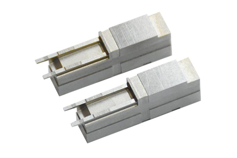

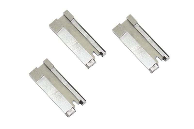




Related Product Catalogue and Quotation










Why Source Connector Mold Slider Inserts from SUUXIANG
A drawing-driven workflow for aligning manufacturability, critical features, process planning, and inspection expectations before production.
Drawing-Led Review
We review drawings, models, datums, mating context, and functional requirements to clarify manufacturability before quotation or production commitments.
Practical DFM Discussion
DFM discussions address tool access, side-action interfaces, electrode needs, wire paths, grinding allowance, and serviceable insert design.
Process-Route Planning
CNC machining, EDM, grinding, fitting, and inspection are considered as an integrated route for the specified component geometry.
Critical-Dimension Focus
Critical-to-quality dimensions, datum relationships, surface requirements, and inspection methods are identified so priorities remain visible throughout manufacturing.
Revision-Controlled Execution
Drawing revisions and project information stay traceable, helping teams prevent avoidable mismatches between approved requirements and shop-floor execution.
Inspection-Matched Delivery
Final delivery documentation is aligned with the order and verified inspection plan, supporting clear acceptance review for connector mold slider inserts.
Precision Tooling and Machined Component Families
Drawing-driven process routes for configurable components, from critical features and tooling interfaces to inspection-ready delivery.

CNC Machining Services
Precision CNC machining services for drawing-based components requiring controlled dimensions, material traceability, and an appropriate route through milling, turning, EDM, grinding, fitting, and inspection. DFM review identifies critical features and manufacturability considerations before quotation and production planning.
Upload a Drawing
CNC Milling
Custom CNC milling services for prismatic parts, inserts, plates, and complex machined features. Tool access, datum selection, wall geometry, corner radii, and machining allowance are reviewed so the programmed route supports the drawing’s critical dimensions and surface requirements.
Upload a Drawing
CNC Turning
Precision CNC turning services for shafts, pins, bushings, sleeves, and rotational features where concentricity, runout, diameters, and shoulder relationships affect function. The process plan considers workholding, material condition, secondary operations, and inspection points identified in the drawing review.
Upload a Drawing
5-Axis Machining
5-axis CNC machining supports components with angled features, compound surfaces, and multiple critical relationships that may benefit from fewer setups. Feasibility depends on geometry, tool reach, workholding, material, tolerance requirements, and the verified route for the specific part.
Upload a Drawing
Swiss & Micro Machining
Swiss machining and micro machining support small-diameter, slender, and detail-intensive components where part support, tool geometry, burr control, and measurement method require careful planning. Drawings should identify critical diameters, lengths, threads, surface needs, and mating-function requirements.
Upload a Drawing
Wire & Sinker EDM
Wire EDM and sinker EDM services address hardened materials, narrow slots, sharp internal profiles, deep features, and geometry inaccessible to conventional cutting. Electrode strategy, wire path, flushing conditions, recast-layer expectations, and finishing requirements are reviewed against the application.
Upload a Drawing
Precision Grinding
Precision surface and profile grinding is used to establish controlled flatness, parallelism, profile, and finished dimensions on hardened or precision tooling components. Grinding stock, heat-treatment sequence, datum references, and inspection method should be agreed before the final process route is released.
Upload a Drawing
Mold Core Inserts & Mold Cavity Inserts
Precision mold core and cavity inserts are manufactured from customer drawings and models for defined molding functions. Reviews address parting-line interfaces, cooling or feature access, steel condition, EDM requirements, polishing allowances, critical cavity dimensions, and inspection expectations.
Upload a Drawing
Ejector & Ejection Components
Ejector pins, sleeves, and ejection components are planned around fit, travel, alignment, wear conditions, and mating-part relationships. The drawing package should define dimensions, materials, heat treatment, surface condition, and any assembly or motion requirements affecting manufacturability.
Upload a Drawing
Core Pins, Guide & Locating Components
Core pins, guide pins, and locating components require controlled relationships to cavities, inserts, or mating tooling. SUUXIANG reviews diameters, engagement lengths, datum strategy, concentricity, fit requirements, material condition, and inspection criteria before selecting the manufacturing sequence.
Upload a Drawing
Slides, Lifters, Gates & Mold Accessories
Mold slides, lifters, gates, and accessories are configurable tooling components whose function depends on movement, shutoff geometry, clearances, and assembly interfaces. Manufacturing planning considers machining access, EDM or grinding needs, heat-treatment sequence, fitting requirements, and drawing revision control.
Upload a Drawing
Connector Mold Components
Precision connector mold components support tooling features where pitch, alignment, pin geometry, insert relationships, and repeatable mating function are critical. Manufacturing plans are based on supplied drawings, material requirements, tool-access constraints, EDM strategy, and defined inspection priorities.
Upload a Drawing
Stamping Die Components
Precision stamping die components are produced for drawing-defined cutting, forming, guiding, and locating functions. Reviews focus on material and hardness requirements, clearance-related geometry, wear surfaces, grinding stock, wire-EDM paths, mating relationships, and measurement requirements.
Upload a Drawing
Injection, MIM, CIM & Overmolding Tooling
Injection, MIM, CIM, and overmolding tooling work is assessed within verified production scope for the requested component or tooling task. The review considers molding-function interfaces, material selection, shrinkage inputs supplied by the customer, tool access, inserts, and required dimensional evidence.
Upload a Drawing
Machining Materials
CNC machining materials are selected from the drawing, application, and customer-specified requirements rather than assumed from a generic list. Material grade, supply condition, hardness, corrosion resistance, machinability, heat-treatment needs, and traceability expectations should accompany the RFQ.
Upload a Drawing
Surface Finishes & Heat Treatment
Surface finishing and heat treatment are planned as part of the dimensional process route, not as an afterthought. Required finish, coating, polishing, hardness, treatment sequence, masking needs, and post-treatment grinding or inspection requirements should be stated before production commitment.
Upload a Drawing
Quality, Metrology & Documentation
Precision inspection, metrology, and quality documentation are aligned to the agreed drawing revision and inspection plan. Customers should identify critical dimensions, datum scheme, sampling or reporting expectations, material records, and any documentation needed for receiving or supplier-quality review.
Upload a Drawing
Prototyping & Low-Volume Production
Rapid prototyping and low-volume manufacturing support drawing-based evaluation parts, tooling components, and controlled production quantities. A useful RFQ includes models, drawings, material, quantity, critical dimensions, finishing needs, inspection requirements, target delivery date, and application context.
Upload a DrawingMaterials for Connector Mold Slider Inserts

Pre-Hardened Tool Steel
Often considered for slider bodies and inserts requiring balanced machinability before final fitting. The drawing review should define hardness condition, wear zones, machining allowance, and whether later EDM or grinding is needed.

Hot-Work Tool Steel
A candidate for connector mold slider inserts exposed to repeated thermal cycling or demanding molding conditions. Selection depends on specified heat treatment, required toughness, surface condition, feature geometry, and the planned finishing sequence.

Cold-Work Tool Steel
Considered where wear resistance and dimensional stability are important for sliding, shutoff, or forming areas. Confirm the requested grade, heat-treatment route, grinding stock, and EDM strategy from the drawing before material commitment.


Tungsten Carbide Inserts
Evaluated for localized high-wear features where insert geometry, support, joining method, and grinding access can be validated. Material use remains dependent on drawing requirements, application loads, tolerance priorities, and manufacturability review.
Connector Mold Slider Inserts: Machining, EDM and Inspection Routes

CNC Milling
CNC milling establishes accessible profiles, pockets, mounting faces and reference surfaces for connector mold slider inserts, with tool approach, corner radii and machining allowance reviewed against the drawing and subsequent finishing route.

CNC Turning
CNC turning supports rotational features such as guide diameters, cylindrical seats and threaded details where concentricity and datum relationships matter. The route is selected when the component geometry can be reliably referenced from a rotational axis.

Wire EDM
Wire EDM cuts precise through-features, narrow slots and difficult internal profiles without conventional cutter access. Wire-path planning, start-hole location, corner conditions and allowable overcut are reviewed against functional dimensions and mating-component requirements.

Sinker EDM
Sinker EDM forms deep cavities, sharp internal detail and enclosed geometry that is impractical for milling. Electrode strategy, flushing access and finishing requirements are defined during drawing review to support the specified feature intent.

Precision Grinding
Precision grinding finishes critical flats, guide surfaces and datum-related dimensions after appropriate stock allowance is retained. The method supports controlled surface condition and dimensional refinement where milling or EDM alone does not satisfy drawing priorities.

Fitting Inspection
Fitting and inspection verify motion interfaces, contact relationships and critical dimensions before delivery. Inspection methods and reporting expectations are aligned to the order, including specified datums, surface priorities, revision status and required traceability.
Connector Mold Slider Inserts and Supporting Accessories

Guide and Locating
Guide elements and locating features support repeatable slider travel and assembly positioning. Specify datum relationships, contact surfaces, fit requirements, and replacement expectations so the selected components can be reviewed against the tooling design.

Retention Fasteners
Fasteners secure inserts, wear parts, and supporting hardware within the slider assembly. Drawing review should confirm thread engagement, head clearance, access for assembly, locking method, and any countersunk or concealed mounting requirement.

Return Springs
Springs may support defined return, retention, or sequencing functions in a slider mechanism. Provide installed space, working travel, force requirement, operating conditions, and service-access needs before a spring arrangement is included.

Wear Components
Wear plates, gibs, and replaceable contact components help manage sliding interfaces where the drawing defines them. Review lubrication provisions, material or heat-treatment requirements, running clearance, backing support, and inspection criteria together.

Identification Markings
Part numbers, revision marks, cavity identifiers, or orientation marks can be added when specified and validated. Define marking location, method, legibility requirements, and whether identification must align with inspection records or assembly documentation.
About Connector Mold Slider Inserts
SUUXIANG is the sole public-facing brand of Dongguan SuuXiang Precision Mold Co., Ltd. Established in 2010, the company is based on the 2nd Floor of Sanhe Industrial Park in Chang’an Town, Dongguan, Guangdong, China. Founder and legal representative XiaoCheng Huang leads the company serving global engineering and sourcing teams with inspected custom CNC parts, precision mold components, connector tooling, and die components made to controlled drawings and specifications.
For connector mold slider inserts, our work begins with drawing review: critical dimensions, datums, material and heat-treatment requirements, machining access, EDM or grinding needs, and inspection expectations. Production planning may combine CNC milling or turning, multi-axis machining, wire or sinker EDM, precision grinding, fitting, and documented inspection.
What distinguishes SUUXIANG is disciplined project coordination before production commitments. We treat slider inserts as configurable, drawing-based components rather than assumed catalog parts, keeping revision control, process decisions, and quality requirements visible throughout the project.

Connector Mold Slider Inserts: From DFM to Inspection
DFM and Datum Review
SUUXIANG reviews the drawing, 3D model, mating context, critical dimensions, datum scheme and surface priorities before quotation. For connector mold slider inserts, this discussion identifies undercut geometry, tool access, tolerance-stack risks and the information needed to define a controlled manufacturing route.
- Confirm critical-to-quality dimensions and functional datums
- Review slider travel, release direction and forming access
- Identify material, heat-treatment and surface requirements
- Record revision status and open technical questions

Planned CNC, EDM and Grinding
The process route is selected around feature geometry, material condition and inspection needs rather than a generic machining sequence. CNC machining establishes accessible geometry; wire or sinker EDM can address constrained details; grinding is planned where flatness, fit or finish requirements call for controlled stock removal.
- Assess machining access before committing to the route
- Plan EDM electrodes, wire paths and flushing considerations
- Allow stock for heat treatment and finish grinding where required
- Align process sequence with the approved drawing revision

Fitting and Inspection Evidence
Fitting strategy focuses on the interfaces that govern slide movement, insert retention and molding function. Inspection planning connects critical features to suitable measurement methods and agreed reporting requirements, so final documentation reflects the order, the verified inspection plan and the delivered connector tooling components.
- Define fit-sensitive interfaces and inspection priorities
- Check critical dimensions against drawing datums
- Match reports and records to agreed quality requirements
- Maintain visible revision and delivery coordination

Connector Mold Slider Inserts: Drawing-Based Review vs. Quote-Only Sourcing
Compare the engineering evidence needed before production—not just the quoted unit price.
← Swipe left or right to view →
Production Workflow for Connector Mold Slider Inserts
A drawing-led route from engineering review through inspected delivery coordination.
RFQ and Drawing Review
Review 2D drawings, 3D models, quantities, application context, critical dimensions, datums, material requirements, surface priorities, inspection needs, revisions, and target delivery requirements before quotation.
DFM and Process Planning
Confirm machining access, slider geometry, EDM requirements, wire paths, electrode strategy, grinding stock, heat-treatment sequence, fitting interfaces, and inspection methods for the approved revision.
Material and Job Preparation
Plan material against the drawing specification, identify traceability needs, release controlled manufacturing information, and align the work route with agreed quality and delivery expectations.
Machining and EDM Execution
Machine connector mold slider inserts using the appropriate CNC, multi-axis, wire EDM, sinker EDM, and turning operations, with process decisions governed by feature access and geometry.
Grinding Fitting and Inspection
Apply precision grinding and fitting where required, then inspect critical dimensions and functional interfaces against the order-specific inspection plan before final release and documentation.
Packing and Shipment Coordination
Protect approved components for shipment, match supplied records to the verified inspection plan, and keep revision, delivery, and project communication visible through dispatch coordination.
Start Your Connector Mold Slider Inserts Project
Provide the engineering inputs early so DFM, process planning, inspection, and production release can be aligned to your drawing requirements.
Submit Complete Design Inputs
Send the 2D drawing, 3D model when available, material, heat-treatment requirement, quantity, application context, and target delivery date for an informed initial review.
Define Critical Requirements
Identify critical-to-quality dimensions, datums, surface requirements, mating relationships, and requested inspection records so the proposed machining, EDM, grinding, and measurement plan addresses project risk.
Review DFM and Quotation
SUUXIANG reviews tool access, machining allowances, electrode or wire paths, heat-treatment sequence, and inspection scope before providing a drawing-based quotation and agreed revision basis.
Approve First-Article Evidence
Confirm first-piece or sampling evidence against the agreed critical dimensions and inspection plan, resolve revisions where needed, then authorize controlled production release.
Connector Mold Slider Inserts: Certifications and Quality Documentation
Customer Reference Publication Policy
Customer testimonial pending written approval. No project outcome or performance claim is published until the customer, project context, and supporting evidence are verified.
Customer testimonial pending written approval. SUUXIANG will publish only feedback tied to a confirmed drawing-based project and documented inspection or delivery evidence.
Customer testimonial pending written approval. Measured outcomes, quantities, lead times, and application results require customer authorization before publication.
Connector Mold Slider Inserts FAQ
Practical RFQ, quality, revision, and delivery questions for drawing-based connector tooling components.
What information should I send for a connector mold slider insert RFQ?
Is there a minimum order quantity for connector mold slider inserts?
Can I order a sample before full production of connector mold slider inserts?
What materials and heat-treatment details do you need?
Can you work from a revised drawing after I submit an RFQ?
What inspection reports can be requested for slider insert components?
How are shipping, payment, and delivery dates handled?
How is confidentiality and IP handled when I share connector mold slider inserts drawings?
Complete Buyer’s Guide to Connector Mold Slider Inserts
Use this practical framework to define functional requirements, evaluate supplier engineering and quality controls, compare tooling options, and avoid drawing, material, tolerance, and cost mistakes before committing to production.
1. What Are Connector Mold Slider Inserts?
1. Connector mold slider inserts are replaceable precision steel components mounted in a side-action assembly. They form geometry that cannot clear a straight opening direction, including side openings, undercuts, latch windows, retaining grooves, and local shutoff details.
2. The insert is the feature-forming, serviceable element; the slider body carries and guides it through its stroke. It is not the main core or cavity, which form primary part geometry, and it is not the complete mold, which also includes plates, ejection, guidance, cooling, and actuation.
3. For connector programs, separating the insert from the slider body lets teams replace or revise the wear-prone feature-forming steel without rebuilding the entire side-action mechanism. The practical objective is controlled side withdrawal before ejection, preserving release clearance while making fitting, inspection, maintenance, and drawing revisions traceable.
2. How Connector Mold Slider Inserts Evolved
Two-piece, straight-pull mold layouts could form only features that released along the opening direction. Side recesses, latch windows, and other trapped geometry were instead addressed by fixed steel, changed parting lines, or hand-loaded pieces when production conditions allowed.
Side-facing connector features created a need for steel that could withdraw laterally before ejection. As housings became more compact and terminal locations more closely related to molded features, separately made slider inserts made it easier to control the forming surface without remaking the complete slide body.
Replaceable inserts also separate wear-prone or damage-sensitive detail from the larger moving mechanism. In repeated production, this supports planned servicing, controlled replacement, and interchangeability when the insert’s datums, fit, revision level, and inspection requirements are defined on the drawing.
3. Types of Connector Mold Slider Inserts
Two drawing views establish the selection: the molding direction and the feature’s release path. Connector mold slider inserts should be classified by the formed feature, retention method, and available travel—not by insert shape alone.
| Configuration | Typical Feature | Movement Or Retention | Benefit And Limit | Drawing Inputs |
|---|---|---|---|---|
| Side-core insert | Side hole or latch recess | Withdraws laterally | Forms undercuts; needs travel clearance | Undercut depth, slide direction, section |
| Shutoff insert | Window or slot edge | Locks against mating steel | Avoids a separate core; flash-sensitive | Shutoff angle, datum, sealing line |
| Interchangeable profile | Pin pattern or cavity detail | Fixed, replaceable pocket insert | Supports variants; interface must repeat | Profile revision, pocket datum, tolerance |
| Hand-loaded insert | Low-volume special feature | Manually placed and retained | Low mechanism cost; slower, operator-dependent | Quantity, loading orientation, retention |
| Angle-pin or cam slide | Side feature with automatic action | Driven during mold opening | Automates motion; requires drive and guide space | Stroke, angle, clearance, timing |
Choose The Release Mechanism
One internal hook may favor a lifter when ejector travel can provide angled release. One side opening may instead be split at the parting line when that avoids a slide without compromising flash control.
Two checks decide the route: complete steel withdrawal and clearance throughout motion. Provide section views, opening direction, ejection stroke, mating-part context, and allowable witness lines.
4. Materials and Heat Treatment for Slider Inserts
Material choice controls whether a slider insert resists resin abrasion, condensation-related corrosion, and repeated side-loads without becoming impractical to machine or repair. Final grade, hardness, and heat-treatment sequence require application-specific engineering review.
| Material Family | Best Fit | Main Trade-Off |
|---|---|---|
| Pre-hardened mold steel | Machinability and repair | Lower wear reserve |
| H13-type steel | Toughness and thermal cycling | Requires controlled heat treatment |
| Stainless mold steel | Corrosion resistance and polish | Higher machining effort |
| High-wear tool steel | Filled-resin abrasion | Toughness and repairability may fall |
Match Steel To Exposure
H13-type hot-work steel is often selected where toughness and thermal-fatigue resistance matter. Pre-hardened mold steels can shorten machining time, while stainless mold steels suit corrosive resin, humid storage, or water-contact risk.
Plan Heat Treatment
Heat treatment changes distortion risk, grind allowance, EDM response, and repair options. Define stress relief, hardening, tempering, and any nitriding or coating only after reviewing geometry, datum surfaces, mating wear plates, and inspection method.
Use Coatings Selectively
PVD coatings may reduce adhesive wear and improve release on suitable, stable substrates. They do not correct poor guidance, inadequate lubrication, cracked edges, or an unsuitable base material.
5. Designing Connector Mold Slider Inserts from Drawings
Two controlled inputs—a dimensioned 2D drawing and native or neutral 3D CAD—should be reviewed with resin, molding direction, and mating-part conditions before machining connector mold slider inserts.
Set Functional Datums
Three datum levels should locate the insert: a mounting datum to the slider body, a molding datum to the cavity or core, and a feature datum for connector geometry. Apply position, profile, and perpendicularity only to interfaces whose variation affects fit, sealing, or terminal alignment.
Define Release Geometry
2–3 mm of preliminary release clearance is sometimes used for compact straight pulls, but actual travel must clear the formed plastic along the real slide axis. Review draft, parting and shutoff surfaces, vent locations, stroke-end interference, and the sequence of slide withdrawal versus ejection.
Specify The Replaceable Interface
Four interface details need explicit control: mounting faces, locating keys or dowels, fastener access, and allowable fitting stock. Ask whether the insert is replaced independently, how it seats against the slider body, which surfaces require grinding, and what inspection datum governs acceptance.
6. Construction and Quality-Control Essentials
Repeatable slide performance is established at the pocket, guide, lock, and service interfaces—not by a final dimensional check alone. SUUXIANG should convert each drawing’s critical features into measurable acceptance criteria and a revision-controlled inspection plan.
Fit And Guided Motion
Specified pocket datums should control insert location, while the drawing defines fit, parallelism, and contact length. Guided travel must be checked across the full stroke for binding, interference, and repeatable return position.
Defined wear faces need accessible lubrication grooves or ports where the mold design requires them. Cooling and vent interfaces must be verified for sealing, clearance, and clean service access.
Locking And Fastening
Positive locking must carry molding load through intended bearing faces, not solely through screws or dowels. Fastener size, thread engagement, torque requirement, and anti-loosening method belong on the assembly record when specified.
Controlled end stops and positioning features should be inspected against their functional datum relationship. A technician should be able to remove the insert without disturbing unrelated guided components.
Inspection Evidence And Trials
A dimensional report should identify measured critical dimensions, instruments, datums, revision, and acceptance result. Material certificates and heat-treatment records should accompany the order when they are specified requirements.
Visual inspection should record burrs, EDM damage, corrosion, and edge condition. Assembly verification and molding-trial feedback should confirm travel, locking, release, witness marks, and any corrective revision before production release.
7. How to Choose a Slider-Insert Manufacturer
One drawing package should reveal whether a supplier can control the slider insert’s functional interfaces. Compare evidence, response quality, and documented process planning—not broad capability claims.
| Evaluation Area | Ask For | Decision Signal |
|---|---|---|
| Engineering | Written DFM | Specific, traceable questions |
| Manufacturing | Process plan | CNC, EDM, grinding rationale |
| Quality | Inspection sample | Revision-linked measurements |
| Delivery | Capacity update | Visible risks and changes |
Engineering Review
Ask the supplier for DFM feedback that identifies datums, inaccessible features, EDM or grinding needs, and unresolved tolerances before production commitments.
A useful response separates assumptions from drawing requirements and records open questions.
- Which dimensions are critical-to-quality?
- What process route protects each datum?
- What changes require drawing approval?
Quality Evidence
Before production, request the proposed inspection method, material traceability, heat-treatment sequence where specified, and sample or first-article records.
A credible plan links measured features to the current revision and inspection equipment.
- Can material certificates accompany the order?
- Which features receive reportable measurements?
- How are nonconformances communicated?
Delivery And Support
At quotation, require capacity and lead-time assumptions, revision-control ownership, protective packaging details, and an after-sales response path.
A supplier should flag schedule changes early rather than treat the quoted date as unconditional.
- Who approves revision release?
- How are inserts protected in transit?
- What support follows receipt?
8. Common Buyer Mistakes with Slider Inserts
2D drawings and 3D models can describe the same insert differently when datums are unstated. Preventable sourcing errors become rework, mold downtime, or disputed acceptance unless questions are resolved before release.
Data And Datum Gaps
2D dimensions without a datum scheme leave suppliers to infer functional relationships, risking mismatched fits. Ask: Which datums govern every critical interface, and does the released CAD match the drawing?
Resin And Cycle Blind Spots
Glass-filled resins, molding temperature, and cycle rate affect wear, thermal behavior, and surface selection. Ask: What resin, filler, molding conditions, and expected production cycle will the insert see?
Tolerance And Material Shortcuts
0.001 mm callouts applied broadly can add grinding and inspection cost without improving function. Ask: Which dimensions are truly critical, and what material properties beyond hardness—wear, toughness, corrosion resistance—are required?
Motion, Spares, And Evidence
3D endpoint checks alone can miss an interference during slider travel; no spare plan can turn a worn insert into downtime. Ask: Has the full stroke been collision-checked, which spares are needed, and what inspection report proves acceptance?
9. From RFQ to Production Release
A controlled release uses defined gates so technical decisions are made before steel is cut. For connector mold slider inserts, the buyer and supplier should record each approval against the current drawing revision.
RFQ And DFM Gate
First, engineering supplies the 2D drawing, 3D model, resin or mating-part context, annual quantity, and critical dimensions. SUUXIANG reviews datum strategy, slide travel, tool access, EDM needs, grinding stock, and inspection feasibility.
Before quotation, unresolved assumptions become written questions rather than implied requirements.
Commercial And Technical Release
Second, procurement aligns price, delivery target, scope, exclusions, and the revision identifier with the reviewed process route. Quality defines material certificates, heat-treatment evidence, inspection points, and reporting format.
Only approved drawings and documented deviations should authorize production release.
First Article And Change Control
Third, SUUXIANG inspects the first article to the agreed plan; the buyer reviews dimensional results and, where applicable, fitting or mold-trial evidence. Engineering owns design changes, quality owns acceptance criteria, and procurement owns commercial authorization.
After release, every change needs a new revision, impact review, and traceable disposition. Spare inserts and replenishment quantities should be planned from wear risk, interchangeability, and lead-time needs.
10. Connector Mold Slider Insert Pricing and Cost Drivers
2 quotation inputs change cost before machining begins: drawing completeness and batch strategy. A dimensioned 2D drawing, 3D model, material, heat treatment, critical datums, finish, quantity, and inspection request let SUUXIANG select a defensible CNC, EDM, grinding, and fitting route.
3 common request categories illustrate the trade-off: simple replacement inserts concentrate cost in setup; complex or hardened inserts add process steps; urgent releases may require different scheduling. Request a drawing-based quote for the specific mating context, revision, and documentation level rather than relying on a unit-price comparison.
| Illustrative request category | Primary cost drivers | Batch strategy and quotation evidence |
|---|---|---|
| Simple prismatic replacement insert | Geometry, material, tolerance, surface finish | Combine identical revisions; provide 2D drawing and quantity |
| EDM-detail or undercut-forming insert | Electrode or wire path, tool access, fitting, critical dimensions | Group related inserts; identify datums and mating surfaces |
| Hardened precision slider insert | Material, heat-treatment sequence, grinding stock, finish | Confirm hardness requirement and post-treatment inspection plan |
| Expedited or documented release | Lead-time urgency, inspection reporting, revision control | State target date, report format, and approval checkpoints |
Upload Connector Mold Slider Inserts Drawings for Review
Include 2D and 3D files, material, quantity, critical dimensions, inspection requirements, and target delivery date for a disciplined DFM and quotation review.