
Custom Core Pins Built From Your Drawing
Move from drawing review to inspected core pins with DFM, CNC machining, EDM, grinding, and controlled quality documentation.
Representative Core Pin Configurations


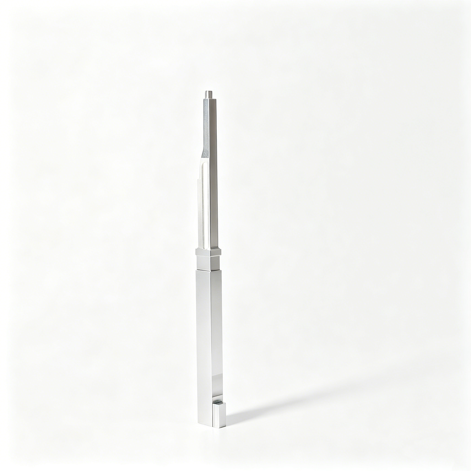


Related Core Pin Configurations and RFQ Options






Why Engineering Teams Source Core Pins from SUUXIANG
A drawing-led workflow for custom core pins, with process decisions and inspection expectations reviewed before production commitments.
Drawing-Led DFM Review
We review geometry, datums, tool access and critical features so the core pin process route reflects the supplied drawing.
Process Route Planning
CNC machining, EDM, grinding and fitting are considered together to match geometry, material condition and functional requirements.
Critical Dimensions First
Project discussions identify dimensions, surface requirements and tolerance relationships that need focused control during manufacturing and inspection.
Revision Visibility
Drawing revisions, clarified requirements and delivery information remain visible through coordination to reduce avoidable production misunderstandings.
Inspection Plan Alignment
Inspection methods and reporting expectations are defined against the order and verified plan before final documentation is issued.
Precision Tooling and Machined-Part Families
Drawing-driven process routes for critical mold, connector, die, and custom-part requirements—from DFM review through inspection documentation.

CNC Machining Services
Precision CNC machining services for drawing-based parts requiring coordinated milling, turning, EDM, grinding, fitting, and inspection. The process route is defined around material, critical dimensions, datum strategy, surface requirements, quantity, and the evidence needed before production is released.
Upload a Drawing
CNC Milling
Custom CNC milling services for prismatic parts, plates, inserts, and features requiring controlled tool access. Drawing review addresses datum selection, pocket geometry, wall conditions, machining allowance, surface requirements, and inspection points before the milling route is confirmed.
Upload a Drawing
CNC Turning
Precision CNC turning services for shafts, pins, sleeves, bushings, and rotational features. Diameter relationships, runout, concentricity, shoulder geometry, material condition, and secondary-operation needs are reviewed against the drawing and mating-part function.
Upload a Drawing
5-Axis Machining
5-axis CNC machining for multi-face components, contoured geometry, and features where additional tool approach can reduce setups. Feasibility depends on part geometry, workholding, tool reach, datum control, material condition, and the required inspection method.
Upload a Drawing
Swiss & Micro Machining
Swiss machining and micro machining for small, slender, and detailed turned components where support, tool access, and feature sequence affect stability. Review includes diameter-to-length relationships, tolerances, burr control, cross features, material, and inspection practicality.
Upload a Drawing
Wire & Sinker EDM
Wire EDM and sinker EDM services for hardened features, narrow slots, internal profiles, sharp-corner requirements, and geometry not accessible by conventional cutting. The route considers wire path or electrode strategy, flushing, recast-layer expectations, stock condition, and finishing needs.
Upload a Drawing
Precision Grinding
Precision surface and profile grinding for controlled flatness, parallelism, profile, and finished-size requirements. Grinding stock, heat-treatment sequence, datum condition, wheel access, surface specification, and measurement approach should be agreed before final grinding.
Upload a Drawing
Mold Core & Cavity Inserts
Precision mold core and cavity inserts configured from drawings for molding surfaces, shutoffs, cooling-related interfaces, and mating geometry. Manufacturing planning considers steel selection, heat-treatment sequence, machining and EDM access, polishing or texture requirements, and critical inspection dimensions.
Upload a Drawing
Ejector & Ejection Components
Ejector pins, sleeves, and ejection components manufactured to the fit, movement, and wear conditions of the mold assembly. Review focuses on diameters, clearance relationships, head and retention features, hardness requirements, surface condition, and mating-component data.
Upload a Drawing
Core Pins, Guide & Locating Components
Core pins, guide pins, and locating components for repeatable mold alignment, feature formation, and assembly positioning. Critical considerations include datum relationships, fit classes, straightness, concentricity, wear surfaces, heat treatment, and inspection of functional interfaces.
Upload a Drawing
Slides, Lifters, Gates & Mold Accessories
Mold slides, lifters, gates, and accessories produced as configurable tooling components rather than assumed stock items. Drawings should define travel or interface geometry, shutoffs, bearing areas, material and hardness, lubrication needs, machining access, and assembly-critical dimensions.
Upload a Drawing
Connector Mold Components
Precision connector mold components for tightly spaced, repeatable features in connector tooling. Component review addresses pin and cavity geometry, pitch relationships, positional control, EDM and grinding requirements, material condition, and inspection methods appropriate to the mating system.
Upload a Drawing
Stamping Die Components
Precision stamping die components for cutting, forming, guiding, and retaining functions within die assemblies. Process planning considers tool-steel condition, heat treatment, clearance-critical features, profile accuracy, grinding stock, wire EDM strategy, and functional datum references.
Upload a Drawing
Injection, MIM, CIM & Overmolding Tooling
Injection, MIM, CIM, and overmolding tooling components produced within verified project scope. RFQs should clarify molding process, material behavior, parting and shutoff requirements, insert interfaces, surface needs, heat-treatment sequence, and the dimensions most critical to molding performance.
Upload a Drawing
Machining Materials
CNC machining materials selected against drawing requirements, application conditions, machining behavior, heat treatment, corrosion exposure, and inspection needs. Submit the specified grade, condition, approved alternatives if any, traceability expectations, and material documentation requirements with the RFQ.
Upload a Drawing
Surface Finishes & Heat Treatment
Surface finishing and heat treatment planned as part of the dimensional process route, not added after machining without review. Specify coating, polishing, texture, hardness, case depth, corrosion needs, masking, critical surfaces, and any post-treatment dimensional verification required.
Upload a Drawing
Quality, Metrology & Documentation
Precision inspection, metrology, and quality documentation aligned to the drawing and agreed inspection plan. Define critical dimensions, tolerancing standard, datum references, sampling or full-inspection expectations, report format, material records, revision status, and traceability requirements before production.
Upload a Drawing
Prototyping & Low-Volume Production
Rapid prototyping and low-volume manufacturing for teams validating geometry, assembly fit, process assumptions, or early production demand. Provide the drawing and model, material, quantity, target date, critical dimensions, surface priorities, inspection needs, and revision-controlled requirements.
Upload a DrawingCore Pins Material Options for Precision Tooling

H13 Tool Steel
A practical option for core pins exposed to repeated thermal cycling in molding or die applications. Selection should be reviewed with heat-treatment requirements, feature geometry, grinding allowance, and the specified inspection plan.

Stainless Tool Steel
Considered where corrosion exposure, resin chemistry, or storage conditions influence tooling decisions. Drawing review should confirm the required grade, hardness condition, surface requirement, critical dimensions, and any documentation expectations before machining.

Tungsten Carbide
Often evaluated for wear-sensitive core pins and fine features where rigidity matters. SUUXIANG reviews geometry, support conditions, mating features, EDM or grinding strategy, and inspection requirements before confirming a viable process route.

Pre-Hardened Steel
Useful when the drawing and application support machining from a supplied hardness condition. The review should address machining access, finish requirements, subsequent EDM needs, dimensional priorities, and the expected operating environment.

Custom Material Grades
For customer-specified grades, production planning begins with the drawing, material designation, heat-treatment requirements, quantity, wear conditions, and quality expectations. Material availability and process compatibility are confirmed before quotation or production commitment.
Core Pins: Machining, EDM and Grinding Processes

CNC Milling Turning
CNC milling and turning establish core pin profiles, shoulders, flats and datum features. The route is selected for accessible geometry and controlled stock, creating a stable foundation for downstream EDM, grinding or fitting where required.


Wire EDM Cutting
Wire EDM produces precise through profiles, narrow slots and complex contours after material condition and wire-path access are reviewed. It is useful where conventional cutters cannot maintain the specified geometry without compromising adjacent features or datums.

Sinker EDM Forming
Sinker EDM forms detailed blind geometry, sharp internal features and difficult-to-access profiles using a planned electrode strategy. Electrode wear, spark clearance and finishing requirements are considered before the process route is committed for core pins.


Fitting Inspection
Fitting and inspection confirm interfaces, functional relationships and drawing-defined critical dimensions before release. The inspection method and required records are aligned with the order, helping teams maintain traceability across revisions, quality expectations and delivery coordination.
Core Pins with Configurable Tooling Features

Locating Features
Shoulders, locating diameters, and anti-rotation flats can establish repeatable position within a mold assembly. Their dimensions, datum relationship, and mating-component fit should be defined on the drawing for engineering review.

Guide Components
Guide pins, bushings, and related alignment interfaces can be coordinated with core pins where mold movement requires controlled guidance. Confirm clearance, lubrication considerations, hardness sequence, and assembly references before manufacturing.

Ejection Interfaces
Ejection-side heads, retention details, and contact surfaces can be incorporated when a component must interface with an ejector system. Review stroke, support condition, surface requirements, and potential wear areas against the complete tooling layout.

Gate Features
Gate-adjacent pins and formed flow features may require precise geometry to support the intended molding design. Provide the part, runner, and cavity context so machining access, EDM strategy, and inspection points can be assessed.

Fastening Details
Threads, cross holes, retaining grooves, and fastening interfaces can be added to support installation or replacement. Thread standard, engagement depth, datum scheme, and any post-treatment requirements should be stated in the RFQ package.
About SUUXIANG Core Pins Manufacturing
SUUXIANG is the sole international-facing brand of Dongguan SuuXiang Precision Mold Co., Ltd., established in 2010 and based in Chang’an Town, Dongguan, Guangdong, China. Founded by XiaoCheng Huang, the company helps engineering, sourcing and quality teams convert drawings and specifications into inspected core pins, precision mold components, connector tooling and custom machined parts.
Our work combines CNC milling and turning, multi-axis machining, wire and sinker EDM, precision grinding, fitting and inspection. For each project, the process route is shaped by the drawing: critical dimensions, datums, material and heat-treatment requirements, machining access, EDM strategy and inspection needs.
What distinguishes SUUXIANG is disciplined project control before production begins. We review DFM and manufacturability, keep revision information visible, and align final documentation with the agreed inspection plan. This evidence-led workflow helps buyers assess feasibility and submit a better-defined RFQ.

Core Pins Capability: From DFM to Inspection
Drawing Review Before Quotation
SUUXIANG reviews core pin drawings alongside 3D models, material requirements, quantities and application context before committing to a process route. The discussion identifies functional geometry, molding interfaces, critical dimensions and revision status so quotation assumptions remain visible.
- Confirm 2D drawing and available 3D model
- Identify critical-to-quality dimensions and datums
- Review material, heat treatment and surface requirements
- Record revision and application context

Machining Routes Matched to Geometry
Core pin geometry may require coordinated CNC machining, EDM and precision grinding rather than a single process. SUUXIANG evaluates tool access, slender features, profile detail, electrode needs, wire paths and grinding allowance to establish a practical, drawing-led manufacturing sequence.
- Assess CNC access for forms and shoulders
- Plan wire EDM or sinker EDM where needed
- Allow grinding stock for final functional surfaces
- Review handling risks for slender pin geometry

Critical Dimensions Planned Early
Dimensional priorities should guide the route before material removal begins. For core pins, SUUXIANG aligns datums, tolerance relationships, concentricity requirements, surface requirements and mating conditions with an inspection approach, helping teams focus controls on the features that affect tooling function.
- Define functional datums and measurement references
- Review tolerance stacks across mating features
- Separate critical features from general dimensions
- Align surface requirements with process planning

Inspection Evidence Prepared to Order
Inspection planning is tied to the approved drawing, revision and agreed reporting needs. SUUXIANG prepares measurement expectations for applicable core pin features and keeps project communication traceable, so final documentation can be checked against the order and verified inspection plan.
- Confirm required inspection and reporting scope
- Match records to the approved drawing revision
- Plan measurement methods for specified features
- Keep delivery and revision information visible

Core Pins: A Controlled Drawing-Driven Workflow
Compare drawing review, process planning, inspection and revision visibility before production commitments.
← Swipe left or right to view →
Core Pins Production Workflow
A drawing-driven path from DFM review to documented inspection and coordinated delivery.
Review RFQ Package
We review drawings, models, quantity, application context, material requirements, critical dimensions, surface priorities, inspection needs, and target delivery before confirming the production route.
Plan Material and Process
The team aligns datum strategy, machining access, heat-treatment sequence, machining allowance, electrode or wire path, grinding stock, and inspection methods with drawing requirements.
Machine Core Pin Geometry
CNC milling, turning, multi-axis machining, Swiss machining, or micro-machining are selected as appropriate to establish the configured core pin geometry and reference features.
Apply EDM and Grinding
Wire EDM, sinker EDM, and precision grinding address profiles, narrow details, hardened features, and finish-critical dimensions according to the approved process plan.
Fit and Inspect Parts
Fitting is completed where required, followed by inspection against the agreed drawing revision, critical dimensions, datum references, and order-specific reporting plan.
Pack and Coordinate Delivery
Verified parts are packed for shipment with documentation matched to the order, while revision status and delivery coordination remain visible to the project team.
Documentation Available by Project Requirement
Provide the engineering inputs early so DFM, process planning, inspection expectations, and delivery coordination can be reviewed before quotation or production.
Send Your Drawing Package
Upload the 2D drawing and, where available, 3D model for the core pins, including revision status, datum references, and mating-component context.
Define Material and Quantity
Specify material, heat-treatment requirements, quantity, application, and expected production conditions so the proposed machining, EDM, and grinding route fits the design.
Identify Critical Requirements
Highlight critical dimensions, tolerances, surface requirements, inspection methods, reporting needs, and any acceptance criteria that must guide DFM and quality planning.
Confirm Timing and Revisions
Share the target delivery date and confirm the latest drawing revision. SUUXIANG reviews manufacturability, process risks, and information gaps before quotation or sampling.
Customer References
Core Pins Customer Feedback and Project Outcomes
Approved customer testimonial pending. Publish only after the customer has confirmed the wording, project scope, measurable outcome, and permission to identify their organization.
Approved customer testimonial pending. Document the drawing revision, critical dimensions, inspection evidence, delivery result, and any quantified outcome before this reference is released.
Approved customer testimonial pending. Use a verified project record that identifies the core pin application, process route, quality requirements, and customer-approved performance result.
Core Pins FAQ for RFQ and Tooling Buyers
Project-specific answers for buyers preparing drawings, quality requirements, and delivery expectations.
What files should I send for a custom core pins RFQ?
Can SUUXIANG manufacture core pins from my drawing?
What materials are available for core pins?
What tolerance can you hold on core pins?
Is there a minimum order quantity for custom core pins?
Can I order samples before a production run?
How long does a core pin order take to manufacture and ship?
What inspection evidence can be supplied with an order?
The Complete Buyer’s Guide to core pins
Use this decision framework to specify core pins, compare materials and manufacturing controls, qualify drawing-driven suppliers, and avoid costly failures involving deflection, wear, tolerances, heat treatment, and inspection.
1. What Are core pins?
One core pin is a precision mold or die component placed in the cavity to occupy the volume that becomes a hole, bore, slot, hollow section, or other internal feature. Resin or molten metal flows around it; after solidification, its displaced volume remains in the part. https://www.sunshinepro.net/core-pins-injection-molding
Two cycle stages make pin stability consequential: filling and packing apply load around the pin, while cooling fixes the feature geometry before release. A slight deflection, wear change, or positional error can shift a hole, alter wall thickness, create flash, or make a mating component fail.
One fixed core pin primarily forms geometry and normally remains stationary through molding and cooling. An ejector pin instead moves during ejection to push the part from the tool; a component can be designed to combine functions, but the drawing must define its intended motion, support, datum, and inspection criteria. https://www.sunshinepro.net/core-pins-injection-molding
2010 is the founding year of Dongguan SuuXiang Precision Mold Co., Ltd.; for drawing-driven work, SUUXIANG should review critical dimensions, material and heat-treatment requirements, machining access, and inspection expectations before confirming a process route. Small pin errors can become recurring part-quality losses and tooling downtime over repeated cycles.
2. How core pins Evolved
Two design shifts changed core-pin practice: molds moved from integral, machined core features and broadly standardized steel pins toward separately mounted, replaceable components made to the drawing. A separate pin localizes wear and damage, so a tool can often be repaired without remachining the entire core block.
Four demanding conditions accelerated that shift: tighter internal geometries, glass- or mineral-filled resins, higher cycle counts, and die-casting heat loads. Medical consumables and connector features also made pin straightness, controlled surface finish, cooling access, and repeatable mating geometry more consequential.
One practical procurement result is that a pin is no longer adequately defined by diameter and length alone. The RFQ should identify datums, functional tip geometry, material and heat-treatment requirements, finish, cooling or vent details, inspection method, revision level, and the replacement-interchangeability requirement; SUUXIANG can review those inputs against a verified machining, EDM, grinding, and inspection route.
3. Types of core pins
Nine core-pin forms address different internal geometries and release conditions. Select geometry from the part function, then confirm support, access, cooling, venting, and inspection requirements on the drawing.
| Type | Geometry Created | Typical Use Or Constraint | Required RFQ Input |
|---|---|---|---|
| Straight | Uniform bore | Simple mold hole; support slender lengths | Diameter, length, datum |
| Stepped | Bore and shoulder | Locating or clearance features; shoulder seating | Step dimensions, tolerances |
| Tapered | Drafted passage | Easier release; taper affects function | Angle, small-end size |
| Headed | Bore with stop | Retention or mounting; head clearance | Head profile, seating |
| Threaded | Internal thread | Unscrewing or release strategy required | Thread standard, pitch |
| Formed-profile | Nonround cavity | Connector or precision features; EDM/grinding access | 2D/3D model, datums |
| Vented | Vented feature | Gas escape; vent must resist blockage | Vent location, resin |
| Cooling | Cooled core | Hot internal zones; channel access limits | Cooling layout, fittings |
| Ejector-style | Feature plus ejection | Moving pin; wear and timing matter | Stroke, fit, surface |
Fixed Geometry Pins
Three fixed forms—straight, stepped, and tapered—create round bores, shoulders, or drafted passages.
Pin diameter, unsupported length, datum, and exit condition govern the design.
Functional Feature Pins
Four specialized forms add retention, threads, profiles, or gas escape.
Their feasibility depends on machining access, release direction, and maintenance access.
Standard Or Custom
Standard pins suit published diameters, simple ends, and conventional seating.
Connector cavities, tight positional relationships, difficult profiles, or combined functions require drawing-based custom design.
4. Materials for core pins
Material selection begins with the resin, casting temperature, pin geometry, finish, and planned replacement method. SUUXIANG should review the drawing’s critical dimensions, heat-treatment callout, and service conditions before confirming a process route.
| Material Family | Main Advantage | Key Limitation | Relative Cost |
|---|---|---|---|
| Tool steel | Balanced toughness and machinability | Moderate corrosion resistance | Low–medium |
| Stainless steel | Corrosion resistance | Lower wear than carbide | Medium |
| H13-type steel | Hot-strength and toughness | Requires controlled heat treatment | Medium |
| HSS or PM steel | Abrasive-resin wear resistance | Higher machining difficulty | Medium–high |
| Tungsten carbide | Wear resistance and stiffness | Brittle; costly | High |
| Copper alloy | Thermal conductivity | Limited wear resistance | Medium |
Match Material To Service
D2-type tool steel suits general wear duty; H13-type steel retains toughness and heat resistance for hot die-casting exposure.
420 stainless steel adds corrosion resistance where molding conditions, resin chemistry, or storage demand it.
Escalate For Wear Or Heat
M2 and PM grades raise wear resistance for abrasive filled resins, but machining and replacement cost increase.
Tungsten carbide provides exceptional wear resistance and stiffness; its brittleness requires sound support, especially on slender pins.
Plan Thermal And Replacement Strategy
Beryllium-free copper alloys can improve local heat transfer where thermal control matters, but they are not default wear materials.
High-volume tools justify replaceable inserts; low-volume work may favor a machinable steel route with documented inspection criteria.
5. Custom core pins and finishes
A custom core pin is defined by its functional interfaces, not its nominal diameter alone. SUUXIANG reviews geometry, process access, and inspection requirements against the drawing before confirming a manufacturing route.
| Option | Useful For | Drawing Requirement |
|---|---|---|
| Shoulder and relief | Location and stress transition | Diameter, radius, datum |
| Thread or mounting head | Retention and replacement | Thread class, engagement |
| Nitriding or PVD | Wear conditions | Treatment, coating area |
| Polishing | Release or cosmetic formed surface | Finish value and area |
Geometry And Mounting

Typical geometry includes straight or stepped diameters, points, flats, threads, reliefs, shoulders, non-round forms, and head or mounting features. Each transition needs a radius, relief, or EDM access strategy where a sharp internal corner is functionally required.
- Identify the locating and forming ends.
- Define thread class and engagement length.
- Show anti-rotation flats or keyed profiles.
Finish Selection
Grinding controls round, cylindrical, and datum-related surfaces; wire or sinker EDM can form inaccessible profiles. Polishing, nitriding, PVD coating, or corrosion protection should be selected for the actual resin, wear, release, and environment—not specified as universal upgrades.
Drawing Information
A production drawing should mark critical dimensions and their datum scheme, required surface finish, hardness, coating specification, and mating conditions. Functional notes should state the formed feature, expected wear mechanism, ejection or sealing role, and inspection or reporting requirement.
6. Core pin Quality Elements
A core pin inspection plan should tie each drawing requirement to a molding failure mode. SUUXIANG reviews material, heat-treatment sequence, geometry, surface condition, and the measurement method before production.
Material And Heat Treatment
Material identity must be traceable to the ordered grade, and heat treatment must follow the agreed sequence. Where case hardening applies, specify required effective depth and the test location; weak or inconsistent hardness can accelerate wear or galling.
Form And Size Control
Straightness, concentricity, and diameter tolerance should reference functional datums and the unsupported working length. A slender pin that deflects can produce oval holes, flash, unequal walls, or inconsistent molded dimensions.
Surface And Geometry Condition
Surface roughness, edge breaks, transition radii, and defect-free working faces require defined acceptance criteria. Sharp transitions concentrate stress, while scratches, burrs, or poor finish can promote sticking, resin pickup, premature wear, and difficult release.
7. Choosing a core pin Manufacturer
Two pre-award reviews should test a manufacturer’s drawing comprehension and evidence trail, not its quotation speed. For core pins, qualify the route from DFM feedback through controlled inspection and shipment.
| Qualification Area | Evidence To Request | Decision Risk |
|---|---|---|
| Engineering | DFM and datum review | Unmachinable feature |
| Materials | Certificates and heat-treatment record | Wrong hardness or grade |
| Quality | First-article report and inspection plan | Unverified CTQ result |
| Control | Revision log and delivery milestones | Wrong revision or late shipment |
Review The Engineering Route
One drawing review should identify CTQ dimensions, datum scheme, tool access, grinding stock, and whether wire or sinker EDM is required. Ask for manufacturability feedback before release, including risks from slender unsupported geometry.
- Which dimensions require grinding after heat treatment?
- What EDM electrode or wire-path constraints apply?
- Which revision governs the quotation?
Verify Process Evidence
Three traceability links matter: material certificate, heat-treatment record, and inspection result tied to the part revision. Confirm available machining, grinding, EDM, metrology, first-article reporting, and protective packaging before approving production.
- Request the proposed inspection plan.
- Define report format and sampling expectations.
- Specify corrosion protection and pack quantity.
Test Delivery Control
One named project owner should confirm capacity, milestone dates, change acknowledgment, and shipment status. Ask SUUXIANG or any candidate supplier how it prevents an obsolete drawing, delayed outside process, or incomplete report from reaching dispatch.
- Who approves engineering changes?
- What triggers a lead-time warning?
- How are first articles separated from production parts?
8. Common core pin Buying Mistakes
Eight preventable gaps commonly turn a simple pin order into rework, delayed tooling trials, or unstable molded features. Resolve them during drawing review, before material purchasing and machining release.
Nominal Dimensions Are Not Enough
1. A diameter and overall length alone omit datum, tolerance, runout, finish, and critical feature locations. The result can be a pin that measures nominally correct but will not seat or form the required feature.
2. Identify functional datums and CTQ dimensions on the 2D drawing, then provide the mating-component drawing or model for review.
Material And Support Gaps
3. Missing material grade, hardness, heat-treatment sequence, and slender-pin support assumptions can cause early wear, distortion, or deflection. Specify the molding environment and require the supplier to review support length, shoulder design, and process route.
4. Lowest unit price is not a material-selection rule. Compare wear, corrosion, thermal demand, replacement frequency, and inspection evidence against the application.
Unclear Interfaces And Inspection
5. Unstated mating tolerances can create interference, looseness, flash, or misalignment at assembly. Define fit relationships, datum transfer, and allowable stack-up with the cavity, insert, or retaining feature.
6. Ambiguous revisions and skipped first-article inspection allow errors to reach mold assembly. Issue a controlled drawing revision and agree the measured features, method, and report before production.
No Replacement Plan
7. A single nonstandard pin with no spare plan can extend downtime after wear or damage. Order traceable spares or retain the approved drawing, material, heat-treatment, and inspection records for repeat manufacture.
9. Launching a Custom Pin Program
One controlled 2D drawing and matching 3D model should anchor the program before quotation. Assign engineering, quality, and procurement owners so functional intent, acceptance evidence, and commercial commitments do not diverge.
Function And Drawing Release
Step 1: Engineering defines the molded feature, mating context, datums, critical dimensions, tolerances, material, heat treatment, finish, and revision level. Quality converts critical features into measurable inspection criteria before release.
- Include quantity and target delivery date.
- Mark dimensions requiring report evidence.
- Freeze the released revision and change route.
RFQ And DFM Closure
Step 2: Procurement issues one RFQ package containing released files, quantities, required documentation, and delivery target. SUUXIANG can review tool access, EDM or grinding needs, allowances, inspection approach, and revision risks; engineering must approve resulting DFM decisions.
- State packaging or traceability requirements.
- Record exceptions in the quotation review.
- Keep one owner for supplier questions.
Approval, Release And Reorder
Step 3: Quality approves a sample or first article against the agreed drawing revision and inspection plan. After approval, procurement releases production, performs incoming inspection against defined criteria, and sets reorder triggers using consumption, lead-time confirmation, revision status, and replacement-risk history.
- Archive approved inspection records.
- Quarantine revision-mismatched deliveries.
- Reconfirm requirements before replenishment.
10. core pins Pricing and Lead Time
2010 is SUUXIANG’s establishment year, but each core-pin quote remains drawing-specific rather than price-list based. Unit cost and schedule change with the manufacturing route, verification scope, and whether a replacement must match an existing mating condition.
3 RFQ files—the 2D drawing, 3D model when available, and revision-controlled specification—make quotations comparable. Include material, heat treatment, coating, critical dimensions, surface requirements, quantity, target date, and required inspection records before route selection.
4 buying situations need different planning: prototypes prioritize feasibility; low-volume orders spread setup across few parts; repeat production benefits from stable revisions; replacement parts require verified interfaces and wear context.
| Pricing or schedule driver | Unit-cost effect | Lead-time effect |
|---|---|---|
| Quantity tier | Prototype and low-volume setup is concentrated; repeat quantities can reduce unit cost | Repeat orders may shorten after revision confirmation |
| Geometry and material | Multi-axis, EDM, grinding, hard material, or difficult access adds process time | More operations and electrode or wire strategy add planning |
| Heat treatment and coating | External processing, distortion control, and post-process finishing add cost | Sequence and supplier coordination add time |
| Tolerance and documentation | Tighter tolerances and inspection reports require more machining and metrology | First-article or added inspection extends release |
| Expedited scheduling | Priority capacity can increase cost when feasible | Only confirm after current capacity review |
Send Your Core Pins Drawing for Review
Upload your drawing with material, quantity, critical dimensions, inspection needs, and target delivery date for a disciplined manufacturing review.