
Stable Narrow Insert for Drawing-Based Review
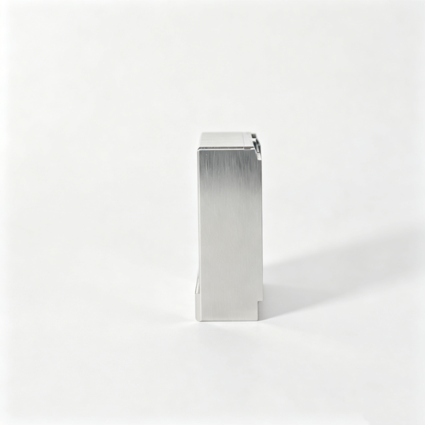
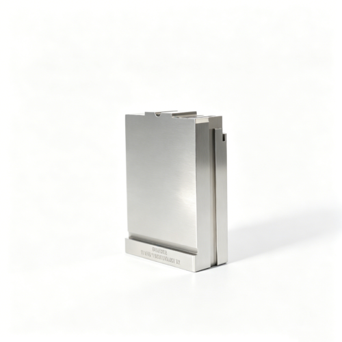
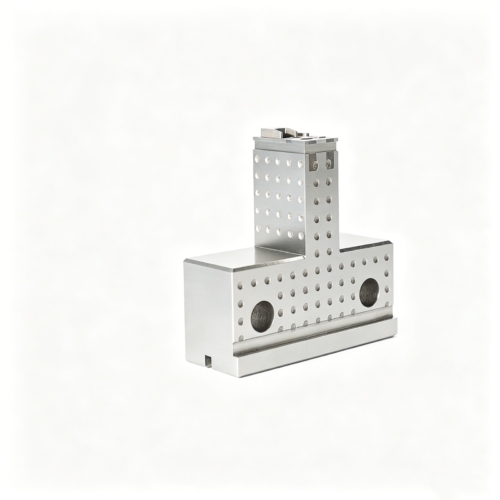
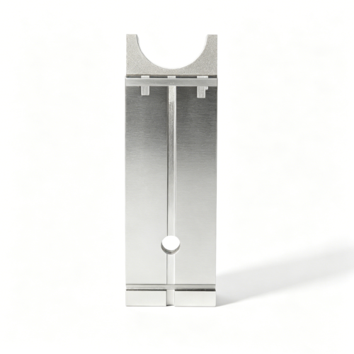
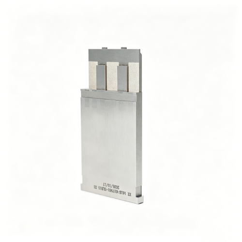
This narrow precision mold insert is intended for applications where width, parallelism, long-face condition and working-end position must remain controlled through machining and inspection. The distinct image from the same-company original product gallery 71792 is a visual reference for form only. It does not establish exact dimensions, material, end function, tolerance or manufacturing history. The approved customer drawing must define the datum sequence, support condition and any thermal or finishing requirements before a route is selected.
Protect the Narrow Body from Distortion
The central RFQ decision is how to maintain body width, parallelism and working-end position without creating clamp distortion. A narrow body may measure differently when it is strongly held, lightly supported or released between checks. The drawing package should identify the intended support points, clamping limits if relevant, and the faces that establish the measurement condition. A consistent datum sequence is especially important when side finishing, end work and optional thermal movement occur at different stages. If the insert is later fitted into a pocket, the locating faces and fit direction should be clearly separated from non-functional surfaces.
Establish a Datum Sequence
Before work is planned, define which long face is primary, which side controls orientation and which end establishes working-end position. The sequence should remain consistent for roughing, finishing and inspection unless the drawing explicitly permits another setup. Width and parallelism should be related to the selected faces, not inferred from a general outside silhouette. Straightness may require its own control or may be included in a profile requirement; that decision belongs in the drawing. If an end feature is critical, show its position from the established datum rather than from an unverified raw edge. These choices make the quotation measurable and reduce interpretation risk.
Conditional Machining Route
A conditional route may use supported roughing followed by heat treatment only when the approved specification requires it. Long faces can then be finished as required, with the working end formed and checked from those finished references. Cutting, grinding, EDM or another suitable method is chosen according to feature scale, access, material specification and the required edge condition. Support may need to change between operations, but each change should be documented and reflected in inspection. Any optional thermal movement or stress-management step must be treated as a drawing or engineering decision, not as an assumed product characteristic. The final sequence remains conditional until the package is reviewed.
Drawing Inputs for a Useful RFQ
Provide the latest controlled drawing, model when available, revision identifier, quantity, orientation and a marked view showing the working end. Include body width, length, parallelism, straightness, end position, corner or edge requirements and all functional fit faces. State whether heat treatment is required, prohibited or still under review. Identify surfaces that may receive support marks, surfaces that must remain cosmetic, and any area requiring later fitting. If the working end has a specific but undisclosed function, the drawing should define its geometry and acceptance criteria without relying on a photograph. This information allows process tradeoffs to be discussed transparently.
Inspection Under an Agreed Support Condition
Inspection should cover drawing-defined width, parallelism, straightness, working-end position and edge condition using an agreed support and measurement condition. Depending on actual size and geometry, checks may include dimensional measurement, optical comparison, profile verification, coordinate measurement or a controlled gauge. The report should state whether the insert was supported continuously, at defined points or in its intended assembly reference. This matters because a narrow part can deflect under clamping or handling. End position should be checked from the same finished faces used to form it. Visual review can identify burrs or damage, but it cannot replace a specified form or location check.
RFQ Communication and Revision Control
For a clear inquiry, identify SKU SUUXIANG-SAMPLE-009 and attach the controlled drawing, model and current revision. List the primary datum sequence, support expectation, required working-end position and any uncertain thermal or finishing decision. Ask for process feedback where a dimension, access direction or support method creates a tradeoff, and record the agreed assumption beside the relevant feature. If the revision changes body width, datum faces, end geometry or heat-treatment instruction, review both the manufacturing route and inspection setup. This revision discipline keeps a narrow insert from being quoted against a visually similar but technically different interpretation.
Part-Specific FAQs
Why is the support condition part of the inspection plan?
A narrow body may deflect or appear different when clamped strongly, lightly supported or released. The drawing and inspection report should therefore state the agreed support and datum condition for meaningful comparison.
Is heat treatment included automatically?
No. Heat treatment or any thermal movement consideration is included only when the approved drawing or engineering review requires it. The route remains conditional until that decision is documented.
Review the Narrow Insert Drawing
Share the current revision and support requirements for a controlled assessment of this precision mold insert.
Reviews
There are no reviews yet.