
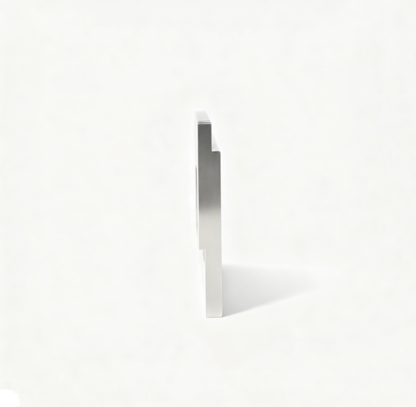
Drawing-Controlled Slim-Profile Insert with Stability-Focused Processing
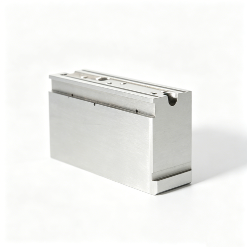
This custom slim-profile mold insert is intended for a drawing-based project where slender geometry, working details, and free-state stability must be managed together. The original gallery image is a visual reference to a slim form only. It does not establish exact profile size, material, tolerance, heat treatment, finish, application, or manufacturing history. The key engineering question is how stock removal, support, stress management, and final inspection will preserve the approved shape.
Slim insert planning with balanced roughing, staged removal, protected handling, intermediate checks, and defined support conditions.
Define the Slim Form in the RFQ
The quotation package should include the latest controlled drawing, revision, units, three-dimensional model if available, quantity, material direction if known, thermal instructions if applicable, surface notes, and inspection requirements. Show the complete envelope, section sizes, straightness and flatness requirements, working-detail position, mounting datums, and any support condition used during assembly or inspection. Enlarged views are useful when a narrow land, end feature, relief, radius, or edge break is functional.
Plan Balanced Stock Removal
Slender parts can bow when material is removed unevenly. A conditional route may use balanced roughing, staged removal from opposing faces, and intermediate checks before the final profile is approached. The amount and order of stock should be based on the approved material and condition. Removing one side to final size while leaving the opposite side heavy can create a temporary shape that changes after unclamping or after the next operation.
Support is part of the process decision. A fixture may reduce deflection during cutting, but a clamped size check can conceal free-state change. The process plan should state when the insert is supported, which surfaces carry the load, and when the part is released for verification. Temporary supports, soft contact points, or controlled orientation may protect the profile without becoming an unapproved feature of the finished component.
Manage Stress and Thermal Sequence
This page does not assign a fixed material or heat-treatment route. If the customer drawing specifies optional or required heat treatment, stress relief, or another material condition, the sequence should leave practical correction stock and stable references afterward. Thermal or stress-related movement may alter straightness, section size, and working-detail position. The final finishing operation should therefore occur only after the specified condition is stable.
Where material or condition remains open, the RFQ should state the assumption and identify the consequence for process planning. A harder condition may favor a different cutting or grinding strategy than a softer precondition. No coating, certification, or performance claim should be inferred. The engineering review should also identify whether the drawing requires a particular edge, surface, or dimensional state before or after any approved material treatment.
Use Light Final Operations
After roughing and stabilization, light final passes may help control the approved straightness, flatness, section size, and working-detail position. Grinding can be considered for accessible planes or edges, but it may introduce heat, alter a narrow section, or change a corner condition. Cutting may be suitable for profiles where access and support are reliable, while a delicate end feature may require a separate operation after the body is stable.
Process tradeoffs should be connected to named drawing requirements. If a plane is a mounting datum, its finish and flatness deserve priority. If an end detail is functional, protect its position while correcting the body. If a side is clearance only, it may not deserve the same finishing allowance. This feature-by-feature logic avoids applying one generic route to a part whose sections have different stability and fit needs.
Protect the Insert During Handling
A slim insert can be damaged before inspection through unsupported lifting, tray contact, clamping, cleaning, or accidental edge impact. Handling instructions may define supported contact zones, protective packaging, orientation, and limits on manual pressure. The working detail should remain protected until the final operation and inspection are complete. Visual review can be used after each major stage to identify chips, dents, burrs, or unexpected edge movement.
Protection must not prevent meaningful measurement. A support that holds the part straight may also mask a free-state bow. For that reason, the drawing or inspection plan should define the intended support condition for straightness, flatness, section size, and feature position. If both supported and free-state results matter, report them separately and explain the fixture or rest points used.
Inspect Shape in the Defined Condition
Inspection may combine optical measurement, surface or edge review, and datum-based dimensional checks. Straightness and flatness should be evaluated in the drawing-defined support condition, with clamping force controlled so the result is not artificially improved. Section size should be checked at the required locations, while working-detail position should be related to the approved mounting datums.
Intermediate checks are valuable before final stock removal. They can reveal bow, twist, local thinning, or movement while correction is still possible. Final review should include the specified profile, end form, edge condition, mounting relationship, and visible handling damage. If a feature is too slender for reliable contact probing, use an appropriate optical or supported method and document any access limitation.
Control the Slim-Insert Revision
For quotation, send the controlled drawing, revision, model, quantity, units, material direction, approved thermal instructions, surface requirements, and expected inspection documents. Mark support points, functional planes, working details, free-state requirements, and any protected edges. Keep the product image separate from contractual geometry. If a later revision changes section size, straightness, end position, or datum structure, reassess the support and finishing sequence.
Frequently Asked Questions
Does the image define the exact slim profile?
No. Profile size, section, straightness, and working-detail position come from the approved drawing.
Why not check a clamped part only?
Clamping can conceal free-state bow or twist. The support condition must match the drawing-defined requirement.
Is heat treatment included automatically?
No. Material and thermal requirements must be confirmed because they may affect stability and finishing allowance.
Submit the Slim-Profile Drawing
Share the controlled profile, support condition, and inspection requirements for a stability-focused RFQ review.
Reviews
There are no reviews yet.