
Engineering article
2D Drawing vs 3D Model Conflicts
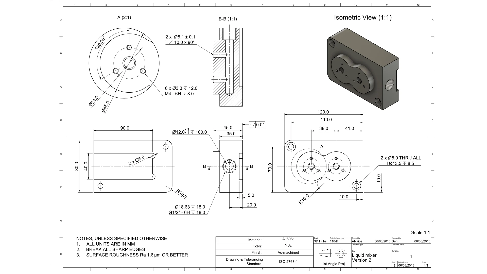
A 3D model and a 2D drawing can describe the same part differently, leaving manufacturing and inspection teams without a reliable acceptance basis. The practical solution is not to assume one format always wins. Establish authority by feature, revision, standard, and inspection method before quotation and release, then document every clarification in the controlled package.
On this page
- Why Conflicts Create Manufacturing Risk
- Define Authority Before Reading Details
- Compare Geometry, Dimensions, and Notes
- Protect Datum and Tolerance Intent
- Turn Resolution Into Inspection Handoff
- Balance Model Convenience and Drawing Control
- Use a Pre-Quote Resolution Checklist
- References and further reading
Why Conflicts Create Manufacturing Risk
A 2D drawing vs 3D model conflict is more than a documentation inconvenience. It can alter the geometry selected for machining, the datum structure used for setup, the gauge or measurement strategy used for verification, and the basis for acceptance. A mismatch may be obvious, such as two hole diameters, or subtle, such as a modeled fillet that differs from a drawing note, an omitted surface requirement, or a datum reference that cannot be inferred from the model.
The common failure is treating the model as visual context and the drawing as a separate administrative file. In production, geometry and requirements are connected. A dimension may establish a functional relationship; a geometric tolerance may constrain orientation; a note may define an edge condition or finish. If one document changes without the other, the package can contain two plausible but incompatible manufacturing instructions. Early resolution protects the design intent and avoids building an inspection record around the wrong definition.
Define Authority Before Reading Details
Before comparing individual features, identify the governing release framework. The purchase order, contract, customer standard, drawing title block, model-based definition policy, and revision-control procedure may establish whether the drawing, the native model, a neutral model, or a combined dataset is authoritative. That answer should be confirmed for the specific program; it should never be assumed from common practice or file format alone.
Authority may also be feature-specific. For example, a model can govern nominal form while the drawing governs dimensions, tolerances, material grade, threads, coatings, marking, or general tolerances. Conversely, a model-based definition package can carry annotations that define these requirements digitally. The controlled revision must be unambiguous across every applicable file. A current model paired with a superseded drawing is not a complete definition, even when the displayed part looks unchanged.
Where documents are silent or contradictory, pause the affected decision and obtain a written disposition from the responsible design authority. A verbal explanation can help a review move forward, but it should be captured in a controlled clarification, revised document, or engineering agreement before it becomes the basis for manufacture or acceptance.
Compare Geometry, Dimensions, and Notes
A useful review proceeds from global definition to feature-level detail. First compare the part envelope, stock assumptions, interfaces, and named coordinate systems. Then examine critical features: holes, threads, pockets, thin walls, radii, chamfers, patterns, seals, bearing locations, and mating faces. Finally, compare non-geometric instructions, including material grade, heat treatment, finish, deburring, cleanliness, identification, packaging, and applicable standards.
Do not limit the comparison to displayed dimensions. The model may show a nominal diameter while the drawing adds a tolerance, a positional control, a depth convention, or a thread callout. A dimension may be theoretically exact, basic, reference-only, or inspection-critical depending on the drafting standard and notation. General notes can apply to an entire part and may change how an apparently simple model feature is interpreted.
It is helpful to classify every discrepancy. Some are presentation differences with no functional effect. Others are missing requirements that require a clarification. The most consequential are direct conflicts: different nominal values, incompatible tolerances, conflicting datums, contradictory material definitions, or a geometry change under the same revision. Each direct conflict needs a recorded resolution, not an informal preference made during programming.
| Conflict type | What to establish before manufacture | Likely record |
|---|---|---|
| Model and drawing show different geometry | Authoritative feature definition and applicable revision | Engineering clarification or corrected release |
| Model lacks a drawing requirement | Whether the note, tolerance, or standard applies to the feature | Feature review note and inspection plan update |
| Drawing dimension is unclear in the model | Nominal geometry, datum interpretation, and measurement method | Controlled response from design authority |
| Files carry different revisions | Current complete document set and effective-date rules | Release-package reconciliation |
Protect Datum and Tolerance Intent
Many expensive disagreements arise when the nominal shape agrees but the tolerance scheme does not. A model can communicate where a feature appears in space; it does not necessarily communicate the functional datum sequence, allowable orientation, form constraint, or relationship to mating parts. A drawing or annotated digital definition may provide this information through dimensions, datums, and geometric controls. Those controls should be interpreted under the drawing standard identified by the released package.
The inspection strategy must follow the agreed definition. If position is controlled relative to a datum reference frame, measurement needs to establish that frame consistently. If profile governs a contoured surface, nominal model geometry alone is insufficient without knowing the specified tolerance zone and references. If a size limit interacts with a mating feature, the applicable material condition and standard determine the interpretation. These are engineering decisions governed by the released requirements, not universal rules.
Manufacturing planning should preserve this chain of intent. Setup surfaces, fixture references, machining sequence, and in-process checks may be selected to support the functional datums, but the process plan does not replace the product definition. When the preferred manufacturing reference conflicts with the specified inspection datum, identify the translation method and verify that it remains traceable to the authoritative requirement.
Turn Resolution Into Inspection Handoff
Resolving the conflict is only the first half of the task. The result must reach the people who program, machine, inspect, and accept the part. A concise feature-resolution log is often effective: identify the feature, cite the conflicting locations, state the governing requirement, identify the authorizing revision or clarification, and note the intended inspection method. This prevents a decision made during quotation from disappearing at release.
An inspection handoff should distinguish product requirements from manufacturing guidance. Product requirements include the accepted geometry, tolerance, datum references, material and finish requirements, and applicable standards. Manufacturing guidance may include suggested holding surfaces, measurement access concerns, or a recommended sequence. Keeping these categories separate avoids accidentally converting a shop preference into a contractual acceptance rule.
For critical interfaces, review measurement feasibility before production. Consider access for probes or gauges, the condition in which the part is measured, the alignment method, and whether surface condition affects the measurement. The drawing, specification, material grade, and engineering agreement control the actual acceptance criteria. When a chosen method cannot demonstrate the requirement clearly, resolve that limitation before production rather than substituting a convenient measurement.
Balance Model Convenience and Drawing Control
Three-dimensional models are highly effective for communicating complex surfaces, assemblies, visual interference, and machinable geometry. They can reduce transcription of nominal form and make spatial relationships easier to understand. Two-dimensional drawings remain valuable when they explicitly organize dimensions, tolerances, notes, datum schemes, and other contractual requirements. Neither format is automatically complete without the organization and controls defined for the program.
A drawing-first package can be easier to archive and review where established drafting standards and conventional inspection records are central. Its weakness is that complex geometry can be cumbersome to dimension fully and may invite manual recreation of nominal surfaces. A model-based package can provide richer geometry and embedded annotations, but it requires compatible viewing, revision, annotation, and archival practices. The right approach depends on the customer's controlled-definition method and the maturity of all downstream users.
The practical objective is a single coherent product definition. If both a drawing and a model are issued, their relationship must be stated. If the drawing is for reference, say so through the controlled release convention. If the model is reference-only, ensure critical requirements are complete elsewhere. If both carry requirements, establish precedence and verify consistency at each revision.
Use a Pre-Quote Resolution Checklist
A careful pre-quote review is the most economical time to surface conflicts. It is not a promise that every production issue has been eliminated; it is a structured check that the quoted scope reflects a usable definition. Reviewers should examine the full package together, including models, drawings, revision history, specifications, request documents, and known mating or functional context. Questions should focus on what governs acceptance and what information is missing to plan the work responsibly.
Escalate ambiguity that affects cost, feasibility, inspection, or risk. Examples include contradictory dimensions, absent tolerances on functional features, undefined material grade, unclear thread designation, missing finish requirements, inaccessible tolerance controls, incompatible units, and uncertainty about digital-model revision. Do not silently select a more convenient interpretation. The resulting assumption may change the product without the design authority's awareness.
Once questions are answered, attach the clarifications to the quote or release record in a form that can be carried forward. If the answer changes the supplied design, request an updated controlled file rather than relying indefinitely on an email thread. That discipline makes subsequent revisions easier to audit and gives engineering, manufacturing, and inspection the same decision trail.
- Confirm the authoritative document, feature-level precedence, revision identifiers, units, and applicable drawing standard.
- Compare critical geometry, dimensions, tolerance controls, datums, threads, material grade, finish, and general notes.
- Identify the planned acceptance method for functional and tightly controlled features, including required datum alignment.
- Record every assumption and unresolved discrepancy; obtain a controlled response before it affects quoted scope or production.
Questions engineers ask
Should the 3D model always override the 2D drawing?
No. The governing source is determined by the controlled release package, applicable standard, contract, and any stated precedence rule. Some programs use drawings as the primary definition; others use annotated digital models. Authority can also differ by feature. Confirm the rule in writing when the package does not make it clear.
What if the model matches the drawing but a note is missing from the model?
Treat the note as an active requirement if the controlled drawing governs it or the release rules incorporate it. Review its scope, the applicable standard, and how it will be verified. If the note changes geometry, material, finish, tolerance, or acceptance, include it in the process and inspection handoff.
Can manufacturing choose an interpretation to keep a quote moving?
A preliminary quote can identify an assumption, but an unresolved conflict should not quietly become the production definition. State the assumption, its impact, and the required clarification. Before manufacture, obtain a controlled resolution or revised package from the responsible design authority.
References and further reading
These resources explain related design and manufacturing principles. Project limits, acceptance criteria and process choices must be agreed against the current drawing.
Publication note: this article is general design guidance, not a material specification, a certified inspection report or a guarantee of process capability.
Turn the drawing into a clear manufacturing brief.
Share the current drawing, material, finish and inspection requirements for a project-specific discussion.