
Engineering article
Go No-Go Gauges vs Variable Measurement
Go no-go gauges give a fast decision against defined limits, while variable measurement produces a value that can support analysis and process control. The appropriate method depends on the feature’s function, tolerance scheme, production stage, risk, and data requirement. A robust drawing and inspection handoff defines the datum strategy, measurement method, sampling, records, and disposition path before production begins.
On this page
Start with the decision required
The central question in go no-go gauges vs variable measurement is not which instrument is more sophisticated. It is what decision the inspection result must support. A limit gauge answers whether a feature passes a defined acceptance boundary. Variable measurement returns a numerical result, allowing the team to compare that result with limits, targets, prior results, and process trends. Both can be appropriate for the same nominal feature at different points in a manufacturing route.
A go or no-go result is often useful where the feature must mate, locate, seal, assemble, or clear another component and the acceptance condition can be represented reliably by a gauge. A recorded value becomes more useful when the distance from a limit affects process adjustment, product behavior, sorting, supplier communication, or future investigation. The drawing, applicable standard, and engineering agreement should establish the controlling acceptance criteria.
- Choose the inspection output before selecting the inspection device.
- Separate functional acceptance needs from process-learning needs.
- Do not assume a pass result reveals how close a feature is to a limit.
What limit gauges establish
A go no-go gauge is designed around permitted boundary conditions. For a hole, a plug gauge may assess whether the opening accommodates the required mating condition and whether an opposing limit is violated. For an external diameter, ring-style or snap-style arrangements can provide comparable boundary checks. Thread gauges similarly assess defined acceptance conditions rather than producing a complete dimensional profile. Gauge selection must follow the feature type, drawing callout, material condition modifiers, and any applicable product standard.
The practical strength of this method is repeatability of a simple inspection action. The operator typically has less interpretation to make than when reading a scale or establishing a measurement strategy from scratch. That advantage depends on a gauge that is correctly specified, maintained, identified, and used at the intended temperature and handling condition. A limit gauge is not a universal substitute for measurement; it reports only the condition it was made to evaluate.
Limit gauging also demands careful interpretation of geometric dimensioning and tolerancing. A feature size limit, positional tolerance, datum reference framework, projected condition, or maximum material requirement may change what a functional gauge should represent. Treating a complex requirement as a simple diameter check can accept parts that do not satisfy the drawing intent or reject acceptable variation. Gauge design should therefore be reviewed against the complete requirement, not an isolated nominal dimension.
- Define which boundary each gauge represents.
- Review material condition and datum references before gauge design.
- State whether the gauge is for final acceptance, in-process checks, or both.
What recorded measurements reveal
Variable measurement provides numerical evidence. Calipers, micrometers, bore measurement systems, comparators, coordinate-based inspection, optical methods, and surface measurement methods can all generate values when their range, resolution, fixturing, uncertainty, and method are suitable for the requirement. The value alone is not enough: its relation to the correct datum system, measurement location, filtering rule where relevant, and environmental condition determines whether it supports a valid acceptance decision.
Recorded values make it possible to see direction and spread. A set of measurements may show a feature drifting toward one limit, widening after a tooling change, or differing among cavities, operations, or lots. This information supports structured corrective action and can support capability work when the sampling plan and measurement-system study are appropriate. A numerical result should not be mistaken for perfect knowledge; measurement uncertainty and method variation remain part of the decision.
Surface requirements illustrate why method definition matters. A roughness callout can affect fit, sealing, wear, coating behavior, or appearance, but the stated parameter does not by itself define every inspection detail. The drawing or applicable standard may need to identify the parameter, evaluation length, cutoff or filter, measurement direction, excluded areas, and acceptance basis. When surface texture is functionally important, a documented variable method is usually more informative than an informal visual judgment.
- Specify the required measured characteristic, not merely an instrument name.
- Identify datum setup, measurement locations, and reporting units.
- Match the method’s uncertainty and repeatability to the tolerance and risk.
Compare speed, information, and risk
The two approaches are complementary rather than mutually exclusive. A production cell may use a limit gauge for rapid routine screening and use variable measurement for first-piece verification, setup approval, periodic audit, investigation, or capability monitoring. This layered plan can preserve fast decisions without losing the information needed to understand a changing process. The right division of work depends on volume, criticality, access, feature geometry, change frequency, and the cost of an incorrect disposition.
Variable measurement can introduce more operator judgment, programming effort, fixture dependence, and cycle time. Limit gauging can conceal gradual drift until a boundary is reached. A sensible inspection plan recognizes these opposing risks. It also defines what happens when the two methods appear inconsistent: verify the part condition, gauge status, datum setup, measurement method, and governing requirement before assigning a disposition.
| Decision factor | Go no-go gauges | Variable measurement |
|---|---|---|
| Primary output | Pass or fail at a defined boundary | Measured value compared with requirements |
| Typical advantage | Fast, direct routine acceptance | Trend visibility and diagnostic information |
| Typical limitation | No indication of distance from a limit | More setup, interpretation, and recording effort |
| Best fit | Stable functional boundary checks | Analysis, verification, development, and controlled adjustment |
| Planning need | Gauge boundary and use conditions | Method, datum setup, uncertainty, and data format |
Translate the drawing into inspection
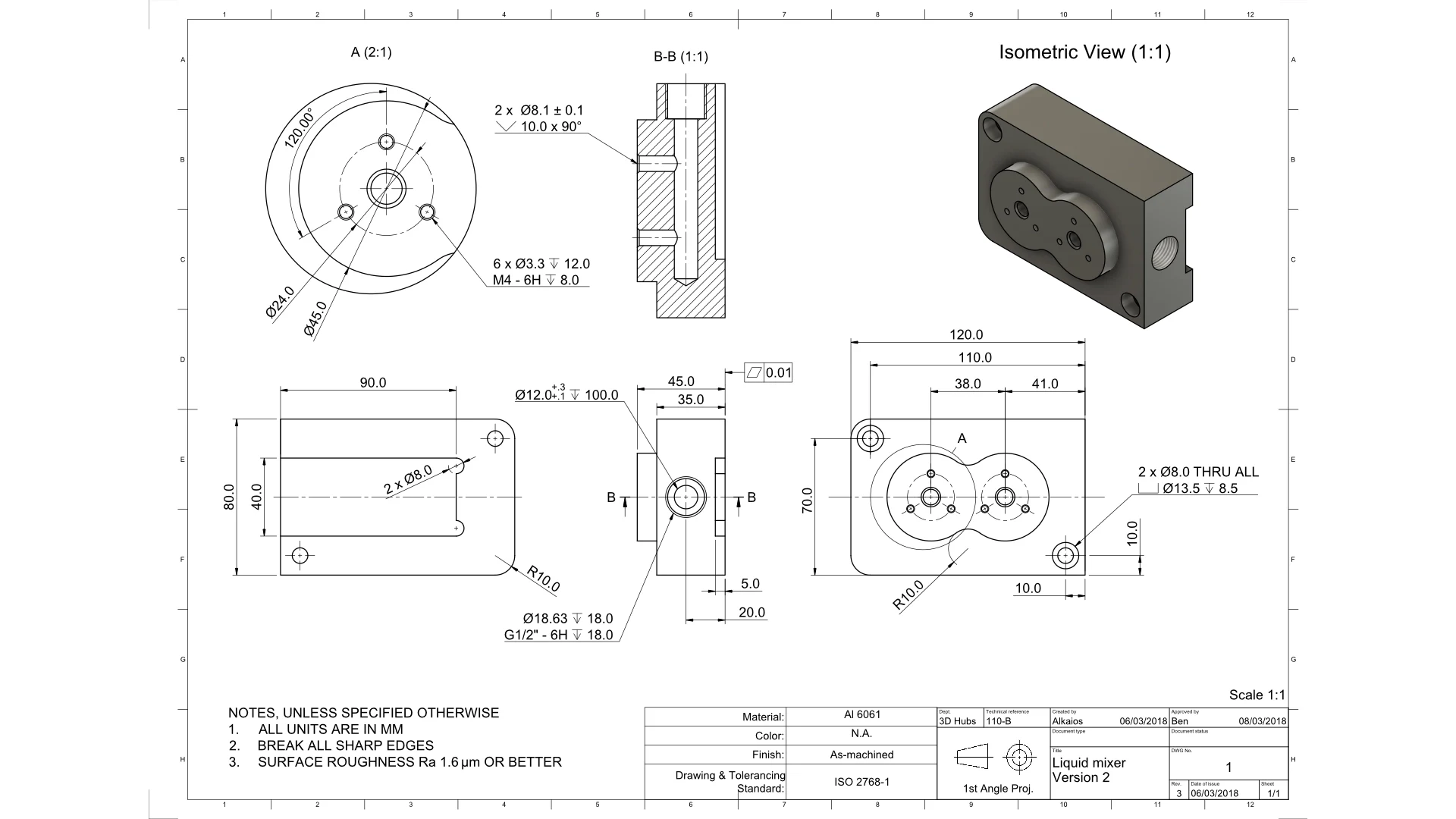
The drawing handoff should begin with feature classification. Identify dimensions that are simple size controls, those governed by geometry, those linked to assembly interfaces, and those with surface, thread, edge, coating, or cosmetic requirements. Then identify the datum structure and the sequence in which the part can be located without creating a different condition from the design intent. A feature may be easy to measure in isolation but difficult to verify meaningfully when its relationship to other features controls function.
For each key characteristic, document the acceptance rule and the planned evidence. The record may be a gauge result, a numerical value, a first-article report entry, a sample log, a controlled program output, or a combination. State the sampling frequency and lot definition only when they are governed by a customer requirement, standard, control plan, or engineering agreement. Avoid inserting a generic frequency because inspection risk varies materially by product and process.
A clear handoff also identifies the authority for ambiguous cases. If a limit gauge is proposed as the acceptance method, establish whether it is a functional gauge, a production check, or a simplified screen. If variable results are required, define rounding, reporting format, data retention, and the rule for values near a specification boundary. These choices should be resolved before conflicting records appear.
- Map every critical feature to an acceptance method and evidence type.
- Link geometric controls to the required datum setup.
- Document escalation for unclear, conflicting, or near-limit results.
Set the plan before quotation
Inspection requirements affect the practical scope of a manufacturing quotation. A request that only names a tolerance may leave unanswered questions about acceptance method, traceability, records, special fixtures, first-piece review, and final documentation. Early agreement prevents one party from assuming rapid attribute checks while another expects complete variable data for every part. It also helps separate essential functional controls from information that is useful but not required for routine release.
The pre-quote review should cover the latest drawing revision and all referenced specifications, material grade where applicable, critical features, datum scheme, inspection stages, and required records. It should also identify customer-supplied gauges or masters, gauge ownership, calibration expectations, handling restrictions, and the disposition process for nonconforming material. Where an inspection approach depends on a process plan or functional interpretation, that dependency should be stated rather than implied.
For SUUXIANG, the most useful technical discussion is one that connects the part’s functional risks to a defined inspection output. A well-prepared package allows the parties to decide where a limit gauge gives sufficient assurance, where a variable value is necessary, and where both forms of evidence are justified. That is a design and quality planning decision, not an automatic choice based solely on production quantity.
- Provide the current drawing, referenced specifications, and revision status.
- List characteristics requiring recorded values or special reports.
- Clarify whether gauges, masters, and inspection data are customer-controlled or supplier-provided.
- Agree on acceptance and disposition rules before commercial scope is finalized.
Questions engineers ask
Can a go no-go gauge replace variable measurement?
It can support acceptance where its boundary condition properly represents the governing requirement and the agreed plan calls for attribute inspection. It does not replace variable data when recorded values, trend analysis, process adjustment, or a different geometric evaluation are required.
Should every drawing dimension have a recorded value?
Not necessarily. The drawing, customer requirements, applicable standards, control plan, and engineering agreement determine which characteristics need variable records. Recording every dimension can add effort without improving the decision, while omitting data from critical features can limit investigation and control.
How should near-limit measurements be handled?
Use the documented acceptance rule, including the specified method and its uncertainty treatment where applicable. Confirm the correct drawing revision, part condition, datum setup, and instrument or gauge status. Escalate ambiguous results under the agreed disposition process rather than relying on an informal retest.
References and further reading
These resources explain related design and manufacturing principles. Project limits, acceptance criteria and process choices must be agreed against the current drawing.
Publication note: this article is general design guidance, not a material specification, a certified inspection report or a guarantee of process capability.
Turn the drawing into a clear manufacturing brief.
Share the current drawing, material, finish and inspection requirements for a project-specific discussion.