
Engineering article
Threaded Hole Design for CNC Machining
A reliable threaded-hole design begins with the joint, then separates functional thread length from manufacturing depth. Review the selected hole style, machining access, material and finish effects, drawing notes, and inspection expectations together. The result is a clearer request for engineering review and a more workable CNC machining quotation.
On this page
Define the Mating Interface First
A threaded hole is part of an interface, not an isolated diameter in a model. Start by identifying the mating component, the fastener type, the direction of assembly, and the surface on which the joined parts seat. Also consider whether the fastener is installed during final assembly, service, or a fixture operation. These facts establish what the thread must accomplish before a machining method is discussed.
Ask practical questions early: Does the mating part need to sit flush against this face? Can a driver reach the fastener without crossing another feature? Is the hole intended to retain a cover, position an assembly, or accept temporary tooling? A hole used for repeatable fixturing may need a different reference relationship than a hole used only for closure. Confirm the functional intent with engineering when it is not explicit.
- Identify the mating fastener and where its head or shoulder bears.
- State the assembly direction and any restrictions on installation access.
- Distinguish retention, alignment, lifting, service, and fixture functions.
- Mark surfaces whose relationship to the threaded hole affects the joint.
| Review item | What to define | Why it matters |
|---|---|---|
| Joint purpose | What the connection must do in the assembled product | It frames the thread and seating requirements for engineering review. |
| Mating condition | Fastener form, bearing surface, and assembly direction | It reveals interference, access, and reference concerns. |
| Service condition | Whether removal, replacement, or repeated use is expected | It may change the preferred feature details or verification focus. |
| Authority | Which drawing, model, or controlled note governs the feature | It prevents conflicting interpretations during quotation. |
Choose Blind or Through Holes
Choose a through hole when the part geometry and product function allow the tool to pass through, debris can exit acceptably, and the opposite face is not restricted. A blind hole is appropriate when breakthrough would affect sealing, appearance, adjacent geometry, or the intended assembly. The choice should be based on the complete part, since a through feature can introduce a concern on a surface far from the fastener.
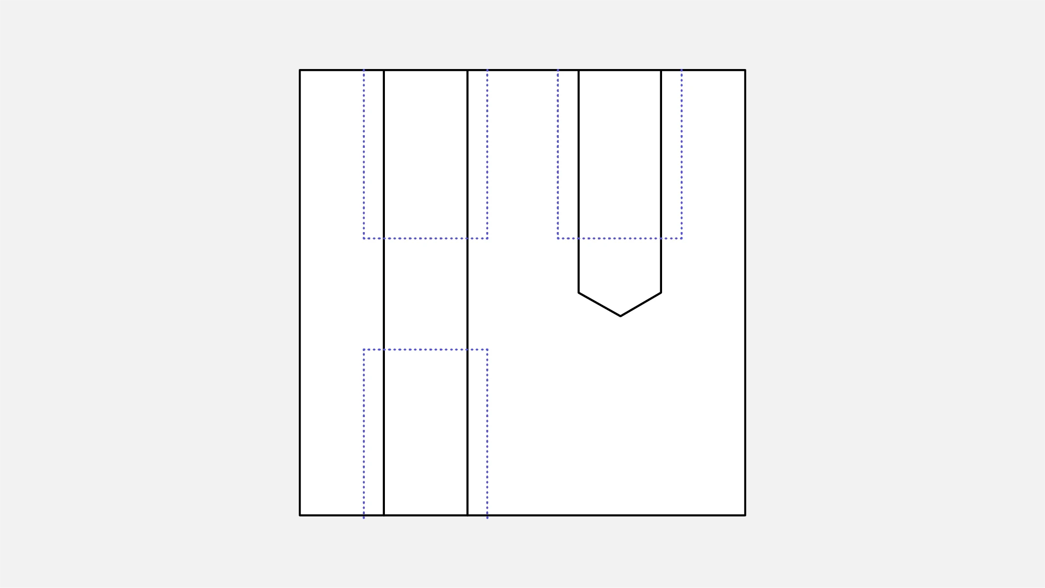
Blind holes require an explicit bottom condition because the drilled form and the usable internal thread do not end in the same place. The thread-making approach, bottom geometry, and nearby wall thickness all deserve review. For example, a recessed attachment point inside a housing may need a blind hole to preserve the exterior surface, while an underside opening may make chip removal and machining access more complicated. Resolve that tradeoff with engineering.
- Check whether breakthrough is functionally acceptable on every affected face.
- Show the required condition at the blind-hole bottom.
- Review nearby cavities, seals, cosmetic faces, and internal components.
- Ask whether the selected thread-making process affects the preferred hole form.
Related technical reading: [3] Threading application guide
Separate Thread and Drill Depth
Specify usable thread length as the portion intended to receive the mating fastener, and specify drill depth as the manufactured hole extent when it is relevant. Treat them as separate requirements rather than expecting one depth value to communicate both. A blind hole generally includes an unthreaded bottom region created by the tool and process, so CAD geometry alone can leave the intended functional condition unclear.
- Place thread and total drilled-depth requirements in distinct callouts when both govern.
- Define whether a bottom clearance zone is functional or only process-related.
- Check the fastener’s installed position against the usable thread region.
- Escalate engagement adequacy to the responsible engineering authority.
Related technical reading: [3] Threading application guide
Plan Tool and Chip Access
A thread feature needs a practical route for drilling and thread creation. Review the approach direction, surrounding walls, adjacent pockets, and any need for the part to be repositioned. A nominally accessible hole can become difficult when a long tool must reach past a flange or when a nearby internal corner limits cutter movement. Keeping critical relationships within a practical machining setup can also simplify control of their relative position.
Chip behavior matters especially in enclosed or blind locations. The material, hole orientation, tool choice, and local geometry influence whether chips can be cleared without compromising the intended feature. Do not solve access by casually opening a relief or moving a wall: those changes can affect strength, sealing, appearance, or assembly. Instead, present the constraint and ask for a manufacturability proposal that engineering can approve.
- View the hole along its machining axis, not only from the assembly view.
- Inspect clearance around the complete tool path and workholding contact areas.
- Identify cavities where chips or coolant may be difficult to manage.
- Flag positional relationships that should be preserved within a chosen setup.
Related technical reading: [1] Locating and clamping principles · [3] Threading application guide

Match Material and Finish
Material selection changes how a threaded hole is produced and how it behaves during assembly. Ductile, abrasive, heat-treated, thin-walled, or coating-sensitive materials can each change the review conversation. Provide the exact material specification and condition, rather than a broad family name, when those details are controlled. If inserts, forming operations, or special thread methods are being considered, their suitability must be agreed with engineering for the particular joint.
Finish sequence should be considered before the thread note is released. A coating, plating, conversion treatment, blasting operation, or masking requirement can change surface condition, alter access, or require protection of a functional area. State whether threads are to be treated, masked, cleaned, or otherwise handled after machining. If the finish supplier and machining plan create conflicting requirements, document the decision rather than leaving it to inference.
- Provide the controlled material grade, condition, and any applicable heat treatment.
- Identify finishes that touch the threaded area or adjoining seating face.
- Clarify whether inserts or alternative thread processes are design-approved.
- Request engineering agreement when finish sequence may affect assembly fit.
Document Drawing and Inspection
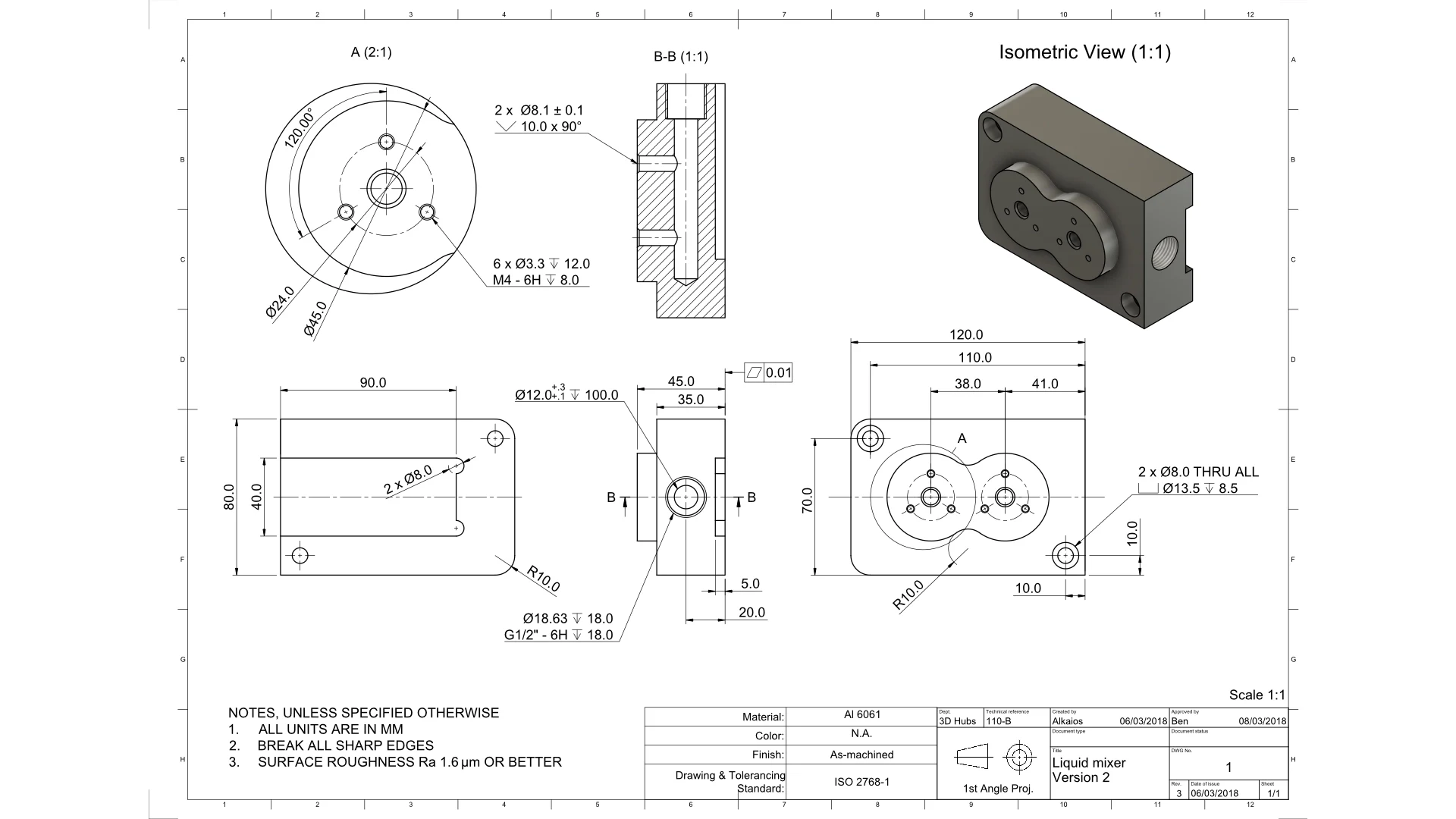
Use the drawing to communicate feature information that is not reliably expressed by the solid model. This includes the thread designation, usable thread requirement, depth definitions, applicable finish treatment, and the datum or reference scheme for position when needed. Clearly identify which document has authority if the model, drawing, purchase specification, or assembly requirement could be read differently. Ambiguity at this stage is more costly than a concise clarification.
Inspection planning should follow function. Decide which threaded-hole attributes require confirmation, which reference surfaces establish the part orientation, and whether verification occurs during machining, at final inspection, or both. In-process probing can support setup and process control, but it does not replace the acceptance method specified for the part. A critical interface should have a defined inspection basis agreed by the design and manufacturing teams.
- Give the thread callout, depth information, and finish requirements a clear drawing location.
- Define datums or functional references where hole position is critical.
- State the acceptance method for attributes that need special verification.
- Separate in-process control from the final acceptance requirement.
Related technical reading: [2] How probing helps machining · [1] Locating and clamping principles
Run a Pre-Quote Review
Before requesting a quote, review the complete threaded-hole package in the same order a manufacturer will need to interpret it: assembly function, feature type, usable thread and drill depths, access, material, finish, and inspection. Include current CAD, the controlled drawing, and any relevant assembly views. A concise list of open questions is useful when the design intentionally leaves a manufacturing choice undecided.
For example, a part may show a blind attachment hole next to a sealed cavity, with a coated exterior face and limited driver clearance. Rather than prescribing an unsupported solution, identify those constraints and ask SUUXIANG to review the manufacturing implications. Engineering should then approve any change to hole direction, bottom detail, finish handling, thread method, or inspection approach that affects the product definition.
- Confirm that CAD, drawing, revision status, and material specification agree.
- List each threaded feature that has a special functional or cosmetic constraint.
- Attach assembly context where installation direction or tool clearance is relevant.
- Record decisions requiring engineering approval before release to production.
Questions engineers ask
Can a CAD thread feature alone define a blind threaded hole?
Usually, it does not fully communicate the manufacturing and functional intent. The release information should distinguish the required usable thread region from any total drilled depth and clarify the expected bottom condition when it matters. It should also state the governing drawing or specification. If the thread method or bottom detail affects the product, obtain engineering agreement rather than relying on a generic model feature.
Should every threaded hole receive the same inspection requirement?
No. Inspection should reflect the function and risk of the individual interface. A noncritical closure thread and a thread that establishes an important assembly relationship may need different documentation and verification attention. Define the relevant references, acceptance method, and any special attributes in the controlled product information. Manufacturing process checks can support consistency, while final acceptance remains governed by the agreed requirement.
What should be sent for a threaded-hole quotation?
Send the current CAD model, controlled drawing, material and finish specifications, quantity context, and any assembly information needed to understand the joint. Call out usable thread requirements separately from drill depth where applicable, and identify blind-hole, access, cosmetic, sealing, or inspection constraints. Include unresolved choices as questions for manufacturability review, then route product-affecting recommendations to engineering for approval.
References and further reading
These resources explain related design and manufacturing principles. Project limits, acceptance criteria and process choices must be agreed against the current drawing.
Publication note: this article is general design guidance, not a material specification, a certified inspection report or a guarantee of process capability.
Turn the drawing into a clear manufacturing brief.
Share the current drawing, material, finish and inspection requirements for a project-specific discussion.