
Mold Components Overview for Drawing-Driven Sourcing
Use this mold components overview to identify functional systems, critical dimensions, and RFQ details before selecting a manufacturing route.
Understand Mold Component Systems Before Sourcing
Review functional roles before defining configurable components, critical dimensions, material requirements, and the manufacturing route for your drawing.
Mold Base Structure
Plates, supports, and locating features establish the tool framework and provide reference surfaces for assembly, clamping, and service access.
Molding Components
Cores, cavities, and inserts form part geometry; their datum strategy, machining access, and finishing requirements should be reviewed together.
Feed System
Sprues, runners, and gates direct melt toward cavities. Their layout affects machining details, insert interfaces, and functional requirements.
Ejection System
Ejector pins, sleeves, plates, and return elements release molded parts while demanding controlled clearance, alignment, and wear considerations.
Cooling And Venting
Cooling paths and vent features influence cycle behavior and part quality, requiring practical tool access and sealing review before manufacture.
Guiding And Location
Guide pillars, bushings, and locating elements maintain repeatable mold alignment; fit, lubrication, and mating relationships belong in the drawing review.
Review Component Families Before You Request a Quote
Classify the required part family, then share drawings, critical dimensions, material, quantity, inspection needs, and delivery requirements for an informed review.

CNC Machining Services
Precision CNC machining services for drawing-driven custom parts, planned around material, datums, critical dimensions, tool access, surface requirements, and inspection expectations. Suitable process routes are confirmed during DFM review rather than assumed from a generic quote.
Upload a Drawing
CNC Milling
Custom CNC milling services for prismatic, contoured, and feature-rich components requiring controlled machining access. Share the 2D drawing, 3D model, datum scheme, tolerance priorities, material condition, and any downstream EDM, grinding, or fitting requirements.
Upload a Drawing
CNC Turning
Precision CNC turning services for shafts, pins, sleeves, bushings, and other rotational parts. Review should address concentric features, runout, thread requirements, diameter transitions, material, heat-treatment sequence, and the inspection method needed for functional dimensions.
Upload a Drawing
5-Axis Machining
5-axis CNC machining supports complex geometry, compound angles, and multi-face features where workholding and tool approach affect results. A drawing review should identify datums, inaccessible features, required surface areas, machining allowances, and measurement strategy.
Upload a Drawing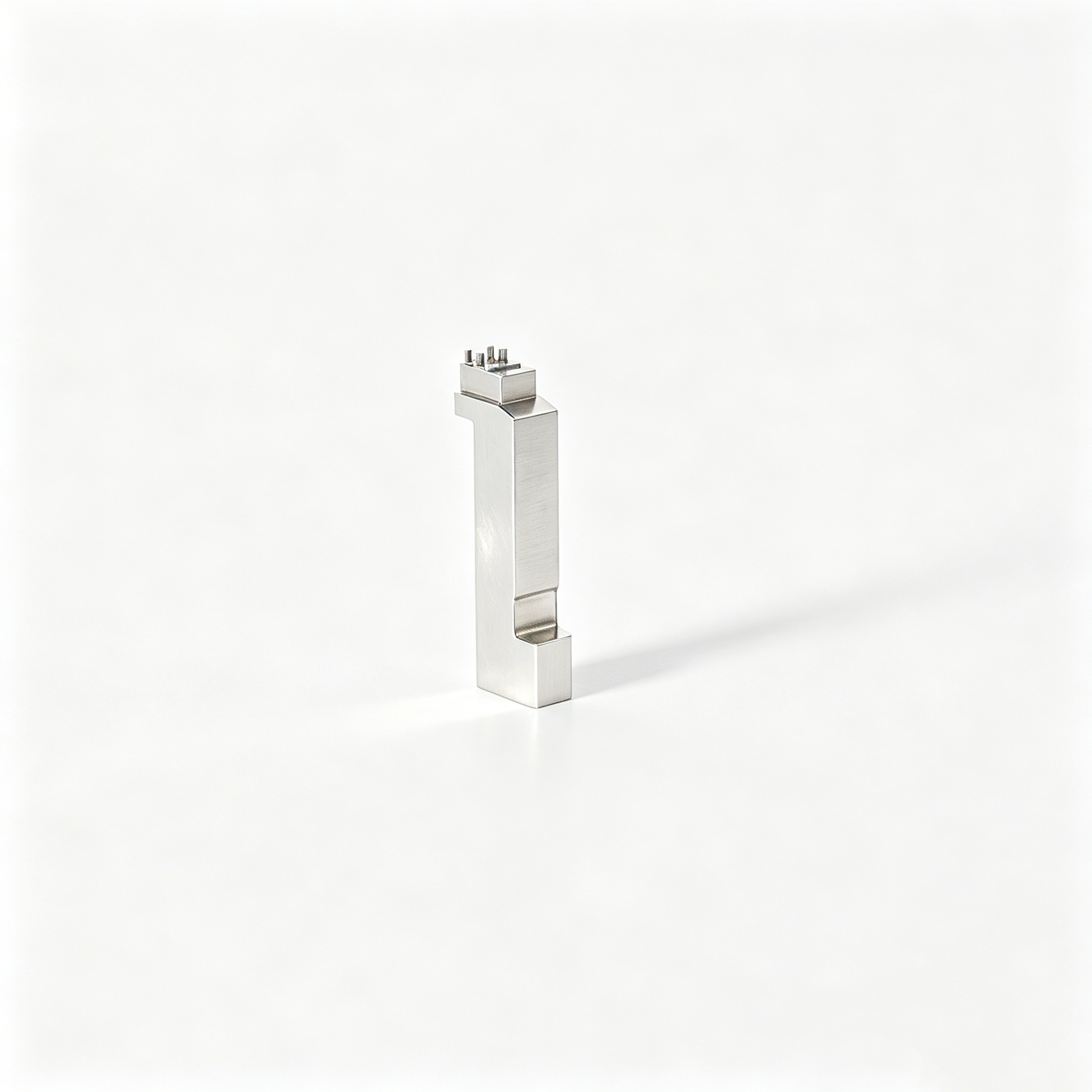
Swiss & Micro Machining
Swiss machining and micro machining support small, slender, or detailed components where stability, concentricity, and handling require careful planning. Provide dimensions, material, quantities, critical features, and mating-part context so the appropriate route can be evaluated.
Upload a Drawing
Wire & Sinker EDM
Wire EDM services and sinker EDM services address hardened materials, narrow slots, internal corners, fine profiles, and shapes inaccessible to conventional cutting tools. Review wire paths, electrode strategy, corner conditions, recast-layer expectations, and finishing or grinding requirements.
Upload a Drawing
Precision Grinding
Precision surface and profile grinding supports flatness, parallelism, profile control, and final size adjustment after machining or heat treatment. Define functional faces, datum relationships, grinding stock, material condition, surface requirements, and inspection criteria before production.
Upload a Drawing
Mold Core Inserts & Mold Cavity Inserts
Precision mold core and cavity inserts are configurable from drawings and mold-design requirements. Reviews consider cavity geometry, steel selection, heat treatment, cooling details, EDM access, shutoff conditions, polishing needs, critical dimensions, and fit with the surrounding mold structure.
Upload a Drawing
Ejector & Ejection Components
Ejector pins, sleeves, and ejection components require attention to diameter control, sliding fit, hardness condition, surface finish, and wear-related interfaces. Include the ejection layout, mating-hole specifications, stroke context, and critical clearances with the RFQ.
Upload a Drawing
Core Pins, Guide & Locating Components
Core pins, guide pins, and locating components establish functional alignment and repeatable positioning in tooling assemblies. Define datum references, fit classes, guide relationships, material and heat-treatment requirements, and any ground or EDM-finished surfaces.
Upload a Drawing
Slides, Lifters, Gates & Mold Accessories
Mold slides, lifters, gates, and accessories are reviewed as interacting tooling elements, not isolated shapes. Drawings should clarify travel direction, shutoff surfaces, wear areas, mating parts, cooling or venting features, tolerances, and fitting expectations.
Upload a Drawing
Connector Mold Components
Precision connector mold components support detailed connector-tooling geometry, including pins, inserts, cavities, and alignment features. Provide terminal or mating-component context, pitch-critical dimensions, material requirements, EDM needs, polishing expectations, and inspection priorities.
Upload a Drawing
Stamping Die Components
Precision stamping die components include punches, dies, plates, guides, and custom wear components produced to drawing-defined interfaces. A useful review covers strip or part context, clearance relationships, tool steel and heat treatment, grinding stock, surface condition, and inspection needs.
Upload a Drawing
Injection Mold Components, MIM, CIM & Overmolding Tooling
Injection, MIM, CIM, and overmolding tooling components are evaluated against the applicable molding process, material behavior, geometry, and assembly interfaces. Share part or tool drawings, gating and shutoff requirements, critical surfaces, production intent, and verification expectations.
Upload a Drawing
Machining Materials
CNC machining materials should be specified by recognized grade, condition, and any traceability requirement. Material selection affects machinability, heat-treatment route, corrosion resistance, dimensional stability, finishing options, and the inspection plan for critical features.
Upload a Drawing
Surface Finishes & Heat Treatment
Surface finishing and heat treatment are planned with dimensional change, masking needs, wear performance, corrosion requirements, and final surface condition in view. State the specified process, target condition, affected dimensions, cosmetic requirements, and any reporting requirements.
Upload a Drawing
Quality, Metrology & Documentation
Precision inspection, metrology, and quality documentation should match the drawing and agreed inspection plan. Identify critical dimensions, GD&T requirements, sampling or full-inspection expectations, material evidence, revision status, report format, and traceability needs before release.
Upload a Drawing
Prototyping & Low-Volume Production
Rapid prototyping and low-volume manufacturing support controlled validation, bridge quantities, and specialized component requirements. Supply the latest drawing and model, material, quantity, revision, functional priorities, inspection needs, and target delivery date for a practical review.
Upload a DrawingUse Mold-Component Requirements to Plan the Process Route
Review Critical Dimensions First
A drawing review identifies the datums, tolerance stack, surface requirements, and functional interfaces that control the component’s role in the tool. SUUXIANG uses this information to discuss a feasible route before quotation or production commitments are made.
- Mark critical-to-quality dimensions and functional mating surfaces
- Confirm datum references before setting machining and inspection sequence
- Identify material, heat-treatment, and surface requirements early

Plan Tool Access and EDM
Deep ribs, sharp internal corners, narrow slots, and inaccessible profiles can change the manufacturing approach. Evaluating cutter reach, electrode requirements, wire paths, and finishing access helps prevent a nominally correct model from becoming a difficult-to-inspect component.
- Check milling-tool reach, rigidity, and corner-radius limitations
- Define where sinker EDM or wire EDM may be required
- Review electrode access, wire start locations, and finishing strategy

Reserve Grinding Stock
Heat treatment, flatness, parallelism, fit surfaces, and tight locating features often require a controlled grinding sequence. The drawing review should establish machining allowance and the order of machining, thermal processing, EDM, and grinding around the intended datum scheme.
- Specify grinding stock on surfaces requiring final correction
- Align heat-treatment sequence with distortion and finish risks
- Protect datum relationships through intermediate and final operations

Match Inspection to Function
Inspection planning should reflect the dimensions that affect mold alignment, shutoff, ejection, sealing, or connector performance. A clear plan connects drawing callouts with suitable measurement methods, report needs, revision status, and documentation required for the specific order.
- Link critical features to practical measurement methods
- Clarify report format and inspection-sample expectations
- Keep drawing revisions and final documentation traceable

From Drawing Review to Inspected Mold Components
SUUXIANG aligns DFM, critical dimensions, process planning, revision control, and inspection documentation before production commitments.
Submit Complete Design Inputs
Provide the 2D drawing, 3D model when available, material, quantity, application context, delivery target, and required inspection or reporting expectations.
Align Critical Requirements
Review datums, tolerance stack, surface requirements, heat-treatment sequence, tool access, and critical-to-quality dimensions before quotation assumptions are finalized.
Confirm the Process Route
Establish the suitable CNC, EDM, grinding, fitting, and inspection sequence, including machining allowance, electrode strategy, wire path, and revision controls.
Approve Records Before Production
Agree the current drawing revision, inspection method, documentation scope, and delivery coordination details so final records match the verified order requirements.
Mold Components Overview: Sourcing Questions Answered
Practical guidance for preparing drawings, specifications, and inspection expectations before requesting a quote.
What should I include in an RFQ for precision mold components?
How should I specify tolerances for mold components?
Which materials and heat treatments should I list for mold components?
When are CNC machining, EDM, and grinding used for mold components?
What surface finish information should I provide?
Can SUUXIANG provide inspection reports for custom mold components?
How can I avoid fit problems between pins, inserts, and mating components?
What files and details are needed for a useful mold-component RFQ?
Upload Your Drawing for Mold-Component Review
Send your drawing, material, quantity, quality requirements, and target delivery date for a project-specific DFM and inspection review.