
Engineering article
6061-T6 vs 6061-T651 for Machined Parts
6061-T6 and 6061-T651 share an alloy and an artificial-aging condition, but the stock designation can matter when machining removes material unevenly. The practical decision is usually about product form, residual-stress management, geometry, and inspection requirements. A clear drawing and process discussion prevent a temper label from being treated as a complete machining specification.
On this page
Begin With the Temper Meaning
6061 identifies the aluminum alloy composition family; T6 and T651 identify temper conditions rather than separate alloys. In broad terms, T6 describes solution heat treatment followed by artificial aging. T651 is a more specific designation used for certain wrought-product forms: it includes the T6-type thermal condition plus stress relief by controlled stretching. The governing material specification defines the exact meaning for the ordered form.
The distinction is important because a machining program interacts with the condition of the starting product, not merely its chemistry. A part that begins as plate may behave differently from one made from bar, extrusion, forging, or near-net stock. The material callout should therefore connect alloy, temper, product form, and applicable standard instead of relying on “6061 aluminum” alone.
Residual Stress Drives the Practical Choice
Residual stress is internal stress remaining after prior thermal and mechanical processing. It may be balanced in a piece of stock, then become unbalanced as machining removes material from one face, one edge, or one side of a section. The resulting movement can appear during roughing, after unclamping, or later in the route. It is a stability issue, not automatically evidence of poor material or poor machining.
The stretching step associated with T651 is intended to reduce residual stress in product forms for which that temper is specified. That can be useful when substantial material removal is expected, especially from plate-like blanks. It does not eliminate every source of dimensional change. Cutting forces, thermal input, clamping, section stiffness, and the order of operations still influence the final result.
- Treat residual stress as one input to process planning, alongside geometry and fixturing.
- Do not assume that a T651 callout alone defines a distortion-control strategy.
Match Stock Form to Geometry
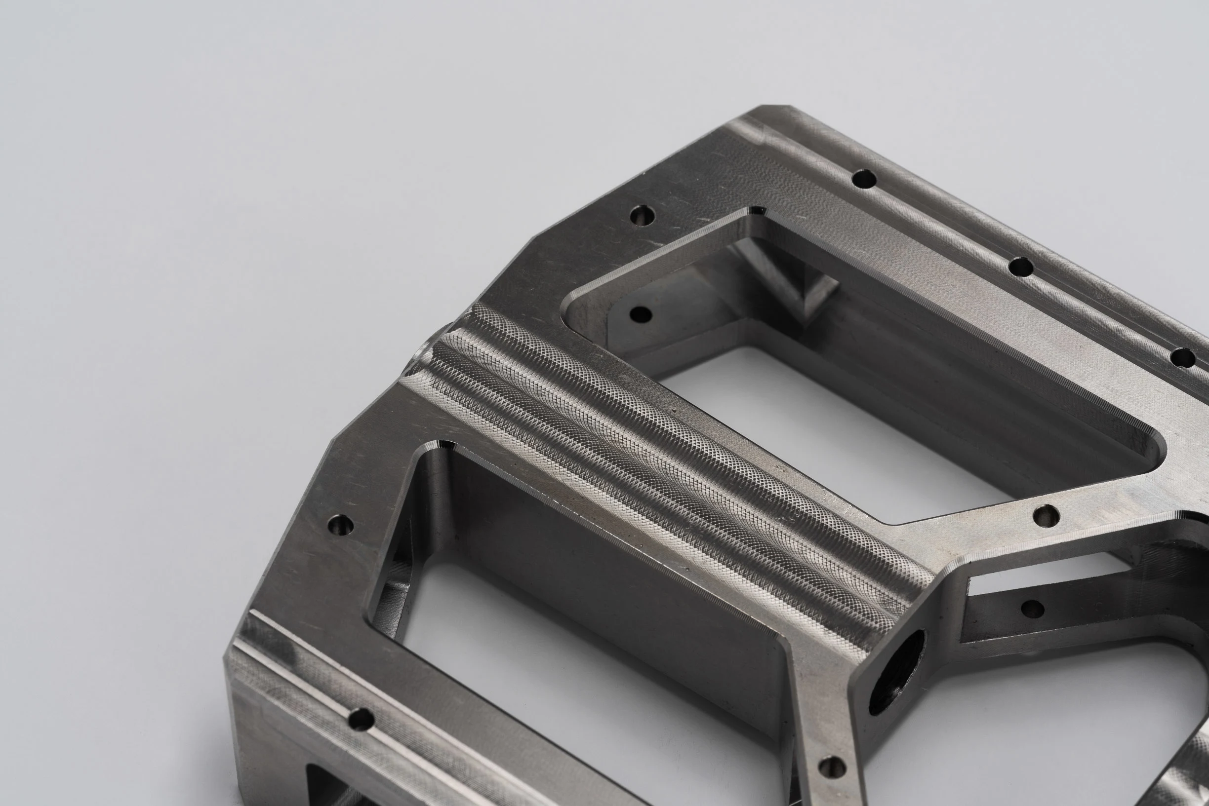
For a flat component machined from thick plate, T651 may be considered when the applicable plate specification offers that condition and the design removes a large share of material. Large pockets, open frames, stepped faces, and broad thin webs can expose internal stress balance as material is removed. A symmetric roughing approach and suitable stock allowance may matter as much as the temper designation.
For round, prismatic, or extruded shapes, the available temper designations and stress-relief practices can differ by product standard. A designer should not transfer a plate convention directly to bar or extrusion. Confirm what stock form will be purchased, whether its temper is available under the cited standard, and whether the planned blank orientation affects grain direction, surface finish, or distortion sensitivity.
| Decision factor | 6061-T6 consideration | 6061-T651 consideration |
|---|---|---|
| Alloy and aging condition | Use the applicable product standard to define the supplied form and temper. | Use the applicable product standard to define the supplied form, aging condition, and stretch stress relief. |
| Heavy asymmetric machining | Plan roughing, support, and inspection around potential movement. | Often worth evaluating when an eligible stock form will undergo substantial uneven removal. |
| Simple, stiff geometry | Temper may be only one of several relevant procurement details. | The added designation may offer limited practical value if geometry and removal are not distortion-sensitive. |
| Drawing control | State form, standard, certification, and critical requirements. | State form, standard, certification, and critical requirements; do not use the temper as a substitute for process controls. |
Design Geometry Before Naming Material
Machining stability begins with the part model. Thin unsupported walls, abrupt changes in section thickness, deep cavities, long narrow arms, and tight flatness requirements increase the importance of sequencing and support. If a feature is sensitive to release from the fixture, the drawing should make the functional condition clear through datums, profile, flatness, parallelism, or other appropriate controls. A vague overall tolerance provides little guidance for process planning.
Consider whether a component needs both faces machined, whether one face is cosmetic, and which surfaces establish assembly location. These decisions affect blank allowance and workholding access. Where a drawing permits it, rounded internal transitions and adequate tool access can reduce local deflection and heat concentration. The acceptable final geometry remains controlled by the drawing and agreed inspection method, not by a general rule about temper.
- Identify functional datums before defining noncritical stock surfaces.
- Flag surfaces that require a final pass after reclamping or after a separate operation.
- Discuss grain-direction preferences only when supported by the design need and material standard.
Plan Roughing, Release, and Finishing
A robust route commonly separates bulk removal from final sizing when distortion risk is meaningful. Rough machining can remove material in a balanced pattern, leaving enough allowance for later finishing. The blank may then be allowed to relax, reoriented, or remeasured according to the process plan. Whether such a sequence is necessary depends on the part, stock, tolerance scheme, quantity, and commercial agreement.
Clamping can temporarily force a flexible part into an apparently correct shape. A final measurement taken while heavily constrained may not represent the free-state part. Process planning should therefore address when critical features are measured and whether inspection occurs in a free state, a defined support condition, or an assembly-like fixture. These conditions should be agreed when they materially affect acceptance.
Write a Complete Drawing Handoff
A material note should identify 6061, the required temper, the product form, and the governing material specification or revision when one is contractually required. If traceability or certification is needed, say what documentation is required. Avoid an ambiguous note that combines incompatible product forms or assumes every form is available in the same designation. The procurement requirement should be reviewed against actual mill-product conventions before release.
The drawing should separately state dimensional tolerances, geometric tolerances, surface requirements, edge condition, finishing requirements, and any restrictions on marking or handling. If material substitution is unacceptable, that should be explicit. If an alternate form may be considered, define the engineering approval path. A temper label cannot establish machining sequence, inspection frequency, surface protection, or acceptance of cosmetic variation.
- Cite the material standard that controls the ordered stock.
- Distinguish a required certification from a preferred document package.
- State whether dimensions apply before or after a specified finish when coating or conversion treatment is relevant.
Use Quotation Questions Early
Before requesting a quote, provide a current drawing, model, annual or lot quantity context, and the intended application constraints that affect inspection or documentation. Describe the blank concept if it is fixed, but allow a machining review when the design does not require a specific route. For a part with thin sections or extensive pockets, identify prior distortion concerns rather than expecting the material designation to communicate them indirectly.
A useful pre-quote discussion asks how stock will be oriented, where material will be removed, which features are most sensitive after unclamping, and what inspection setup is expected. It can also distinguish a functional flatness requirement from a general preference for visual straightness. Those answers support a process plan aligned with the drawing rather than an assumption that T6 and T651 are interchangeable in every product form.
- Provide the latest controlled drawing and native or neutral model as required by the quoting workflow.
- Call out critical-to-function features and their inspection basis.
- Request engineering review when geometry, material availability, or documentation requirements conflict.
Questions engineers ask
Is 6061-T651 always the better choice for machined parts?
No. It can be relevant for eligible stock forms when residual-stress reduction and substantial machining are concerns, but part geometry, stock availability, workholding, sequence, tolerances, and the governing material specification determine whether it is appropriate. A simple, stiff part may not gain a meaningful practical advantage.
Can a drawing specify only “6061-T6/T651”?
That notation is usually incomplete unless an engineering agreement defines its meaning. Specify the required product form and applicable material standard, then select the temper that is valid for that form. If alternatives are acceptable, identify the approval or substitution process rather than leaving the choice unclear.
Will T651 prevent a machined part from moving?
No. Stress-relieved stock can reduce one contributor to movement, but machining can still introduce effects from uneven removal, cutting heat, clamping, tool forces, and low section stiffness. Use the drawing, process plan, and inspection condition to control the finished part.
References and further reading
These resources explain related design and manufacturing principles. Project limits, acceptance criteria and process choices must be agreed against the current drawing.
Publication note: this article is general design guidance, not a material specification, a certified inspection report or a guarantee of process capability.
Turn the drawing into a clear manufacturing brief.
Share the current drawing, material, finish and inspection requirements for a project-specific discussion.