
CNC Chamfer Milling Services for Precision Parts
Send your drawing for CNC chamfer milling services planned around critical dimensions, tool access, inspection needs, and revision control.
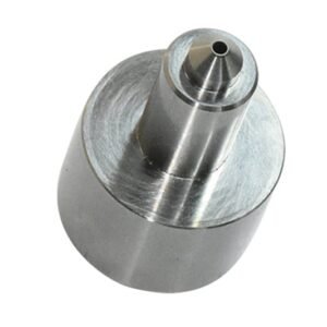
Representative Components for CNC Chamfer Milling Projects





Related Components and Drawing-Based Quotation



Why CNC Chamfer Milling Services Reduce Risk
A drawing-led review aligns chamfer geometry, process decisions, critical dimensions and inspection expectations before production commitments are made.
DFM Before Quotation
Review drawing callouts, datums, tool access and mating conditions early to identify manufacturability questions before the CNC chamfer milling services route is committed.
Critical Dimensions Planned
Separate functional chamfers from general edge breaks, then define inspection priorities around dimensions, surface requirements and assembly-sensitive features.
Appropriate Process Routing
Match milling, EDM, grinding and fitting steps to geometry, material condition, access constraints and the required sequence of operations.
Revision-Controlled Communication
Keep drawing revisions, quality expectations and delivery requirements visible so production decisions remain aligned with the approved project information.
Inspection-Focused Handoff
Agree inspection methods and documentation needs before production, giving sourcing and quality teams a clearer basis for acceptance decisions.
Precision Parts and Tooling Families
Drawing-driven process routes for critical features, controlled revisions, and inspection requirements across custom parts, mold tooling, connector components, and die work.

CNC Machining Services
Precision CNC machining services for drawing-based parts requiring defined datums, critical dimensions, material requirements, and inspection criteria. Process planning combines appropriate milling, turning, EDM, grinding, fitting, and verification steps before production commitments are made.
Upload a Drawing
CNC Milling
Custom CNC milling services for prismatic parts, pockets, contours, chamfers, and fixture-dependent features. Drawing review considers tool access, corner conditions, datum selection, machining allowance, surface requirements, and the dimensions that need planned inspection.
Upload a Drawing
CNC Turning
Precision CNC turning services for rotational components with controlled diameters, concentricity, threads, grooves, shoulders, and chamfers. The process route is reviewed against material condition, workholding, secondary operations, critical datums, and applicable inspection methods.
Upload a Drawing
5-Axis Machining
5-axis CNC machining supports complex angled features, compound surfaces, and multi-face parts where reduced setups can protect positional relationships. Feasibility depends on tool reach, clamping strategy, material, feature geometry, tolerance requirements, and inspection access.
Upload a Drawing
Swiss & Micro Machining
Swiss machining and micro machining support small, detailed components with slender geometries, fine features, and demanding handling requirements. Reviews focus on material form, feature accessibility, burr control, critical dimensions, surface needs, and how each part will be measured.
Upload a Drawing
Wire & Sinker EDM
Wire EDM and sinker EDM services address hardened materials, narrow slots, internal profiles, sharp internal geometry, deep features, and details inaccessible to conventional cutting tools. Electrode strategy, wire path, finish expectations, recast-layer considerations, and inspection points require early review.
Upload a Drawing
Precision Grinding
Precision surface and profile grinding supports controlled flatness, parallelism, profiles, and finishing dimensions after machining or heat treatment. Plans account for grinding stock, datum condition, heat-treatment sequence, wheel access, surface requirements, and final measurement.
Upload a Drawing
Mold Core & Cavity Inserts
Precision mold core and cavity inserts are configured from approved drawings and molding requirements. Manufacturing planning addresses shutoff geometry, cooling or vent features where specified, material and heat treatment, EDM access, grinding allowances, fitting interfaces, and critical molded-part dimensions.
Upload a Drawing
Ejector & Ejection Components
Ejector pins, sleeves, and ejection components are produced to defined diameters, fits, shoulders, tips, and surface requirements. Reviews consider mating bores, hardening sequence, sliding conditions, clearance strategy, chamfers, and inspection of functional features.
Upload a Drawing
Core Pins, Guide & Locating Components
Core pins, guide pins, and locating components require consistent datum relationships across molding interfaces and assembly features. SUUXIANG reviews fit requirements, material condition, guidance surfaces, wear considerations, machining and grinding sequence, and the dimensions governing interchangeability.
Upload a Drawing
Slides, Lifters, Gates & Mold Accessories
Mold slides, lifters, gates, and accessories are manufactured as configurable tooling components rather than stock assumptions. Drawing review considers travel interfaces, shutoffs, angles, wear surfaces, gating geometry, assembly clearances, heat treatment, fitting, and inspection requirements.
Upload a Drawing
Connector Mold Components
Precision connector mold components support high-density tooling features where pin geometry, alignment, cavity relationships, and repeatable inspection matter. Process planning addresses micro features, EDM or grinding needs, material and heat-treatment requirements, mating components, and revision-controlled documentation.
Upload a Drawing
Stamping Die Components
Precision stamping die components are manufactured for drawing-defined die sets, punches, inserts, guides, and forming details. Reviews consider strip direction, working clearances, material and hardness, edge condition, EDM strategy, grinding stock, fit relationships, and inspection requirements.
Upload a Drawing
Injection, MIM, CIM & Overmolding Tooling
Injection mold components and tooling for MIM, CIM, and overmolding are evaluated within verified production scope. Requirements should define material behavior, mold interfaces, critical part geometry, inserts or mating components, surface needs, tooling sequence, inspection expectations, and delivery priorities.
Upload a Drawing
Machining Materials
CNC machining materials are selected against the drawing, application, machinability, dimensional stability, heat-treatment condition, corrosion needs, and finishing requirements. Buyers should identify the specified grade, material form, certification needs, and any approved alternatives before quotation.
Upload a Drawing
Surface Finishes & Heat Treatment
Surface finishing and heat treatment are planned as part of the manufacturing route, not as an afterthought. Requirements should specify finish type, roughness or cosmetic priorities, hardness range where applicable, masking needs, dimensional effects, and post-process inspection expectations.
Upload a Drawing
Quality, Metrology & Documentation
Precision inspection, metrology, and quality documentation are aligned with the order and agreed inspection plan. Customers should identify critical dimensions, datum references, sampling or reporting requirements, material documentation, revision level, and any application-specific traceability needs before production.
Upload a Drawing
Prototyping & Low-Volume Production
Rapid prototyping and low-volume manufacturing support controlled learning before broader release. A useful RFQ identifies quantity, drawing revision, material, target date, functional priorities, critical dimensions, finishing or heat treatment, inspection needs, and expected follow-on production requirements.
Upload a DrawingMaterials Assessed for CNC Chamfer Milling Services

Aluminum Alloys
Lightweight, readily machinable alloys for housings, fixtures, and connector-related components. Their softer cutting behavior can support clean edge transitions, while alloy grade, wall rigidity, and surface-finish requirements should guide the chamfer strategy.

Stainless Steels
Corrosion-resistant materials commonly considered for durable precision parts, tooling details, and industrial assemblies. Their tougher cutting response requires review of chamfer-tool wear, burr control, heat condition, and the specified surface requirement.

Tool Steels
Hard-wearing steels often selected for mold inserts, core pins, and stamping-die components. Material condition and planned heat treatment affect machining allowance, chamfer sequence, EDM or grinding needs, and inspection planning around critical edges.

Carbon Steels
Versatile engineering steels for custom machine parts, fixtures, and structural tooling components. Grade, delivery condition, and corrosion-protection needs influence cutter selection, burr management, post-machining treatment, and the appropriate inspection method.

Copper Alloys
Conductive materials considered for electrical, connector, and specialized tooling applications. Their comparatively ductile cutting behavior can affect burr formation at chamfered edges, so the drawing should define edge condition, surface priorities, and mating context.
Processes That Support Controlled Chamfer Geometry

CNC Chamfer Milling
CNC milling forms specified edge breaks, lead-ins, pocket edges, and accessible contours. Tool selection, datum strategy, and cutter access are reviewed against the drawing so chamfer geometry supports assembly without creating unnecessary machining constraints.

CNC Turning
For rotational features, turning can produce chamfers directly on diameters, bores, shoulders, and threaded entries. Integrating these edges within the turning route helps maintain concentric relationships and avoids an additional setup where geometry permits.

Wire EDM
Wire EDM supports profiles and internal features where milling-tool access is restricted or where hardened material affects the route. Wire-path planning and start-hole location are reviewed to protect critical edges, corners, and datum relationships.

Sinker EDM
Sinker EDM is considered for recessed or complex geometry that cannot be reached reliably with a cutter. Electrode strategy, spark allowance, and downstream finishing requirements are coordinated so adjacent chamfered features remain functionally defined.

Precision Grinding
Grinding refines datum surfaces, critical faces, and controlled stock after machining or heat treatment. The sequence is planned with chamfer dimensions in mind, helping prevent edge damage while supporting the specified surface and fitting condition.

Fitting Inspection
Fitting and inspection verify that chamfers, mating interfaces, and critical dimensions align with the approved drawing and inspection plan. Revision control, measurement method, and any application-specific assembly context should be confirmed before production release.
CNC Chamfer Milling Services: Component Hardware and Identification

Dowel Pin Locations
Specify dowel-pin diameter, fit, datum relationship, insertion direction, and mating-part condition. These locating elements help control repeatable mold or fixture alignment and should be reviewed with surrounding chamfers, wall thickness, and machining access.

Guide Component Seats
Define guide-pin, bushing, or locating-component seats with their functional dimensions, surface requirements, and assembly sequence. SUUXIANG can review whether milling, grinding, EDM, or fitting is appropriate for the specified interface and available tolerance stack.

Fastener Counterbores
Include fastener type, thread callout, counterbore or countersink geometry, engagement requirement, and clearance conditions. Clear definitions prevent interference between mounting hardware, chamfered edges, tool paths, and adjacent mold or connector-tooling components.

Part Identification Marks
State part number, revision, marking method, location, orientation, and legibility requirement in the drawing package. Controlled identification supports component matching, inspection records, revision control, and traceable coordination across multi-part tooling assemblies.

Assembly Reference Labels
Provide label content, attachment location, material constraints, and any environmental or handling considerations when labels are required. Assembly references can reduce mix-up risk during fitting, shipment, maintenance, or installation of related precision components.
About SUUXIANG’s CNC Chamfer Milling Services
SUUXIANG is the sole international-facing public brand of Dongguan SuuXiang Precision Mold Co., Ltd., established in 2010 in Chang’an Town, Dongguan, Guangdong, China. Founded by XiaoCheng Huang, the company helps global engineering and sourcing teams move from drawings and specifications to inspected custom CNC parts, precision mold components, connector tooling, and stamping-die components.
Our CNC chamfer milling services are planned from the drawing outward. Before quotation and production commitments, we review critical dimensions, datums, chamfer callouts, machining access, material requirements, surface priorities, and inspection needs. CNC milling and turning, multi-axis machining, EDM, grinding, fitting, and inspection are combined only where the project requirements support the route.
What differentiates SUUXIANG is disciplined project control around the details that affect part acceptance: DFM feedback, revision visibility, machining allowance, EDM or grinding strategy, inspection method, and delivery coordination. Send the 2D drawing, available 3D model, material, quantity, quality requirements, and target date so the manufacturing discussion can begin with usable evidence.

CNC Chamfer Milling Services: Process Planning in Depth
DFM and Datum Review
CNC chamfer milling services begin with a drawing review that identifies functional chamfers, critical dimensions, datums, mating conditions, and tool access. This establishes whether an edge break is cosmetic, assembly-critical, or part of a controlled tolerance stack before programming begins.
- Confirm chamfer callouts, angles, widths, and applicable edges
- Relate chamfer geometry to drawing datums and mating features
- Flag inaccessible edges, thin walls, and ambiguous notes
- Align revision-controlled models and drawings before release

CNC, EDM, or Grinding
Process selection follows geometry rather than a default machine route. CNC milling may suit accessible chamfers, while wire EDM, sinker EDM, or grinding can be considered where hardened material, internal detail, corner conditions, or surface requirements change the practical manufacturing strategy.
- Assess cutter approach and exit paths for each chamfer
- Review EDM needs for confined or hardened features
- Plan grinding where final geometry requires controlled stock removal
- Sequence machining around heat treatment and fitting requirements

Grinding Allowance Strategy
A chamfer near a ground surface requires deliberate allowance planning. SUUXIANG reviews which features are machined before heat treatment, which are finished afterward, and whether the chamfer must be protected, re-cut, or inspected after grinding to avoid unintended geometry changes.
- Define stock remaining before final grinding operations
- Check chamfer position against finished ground surfaces
- Consider heat-treatment distortion in the process route
- Document any post-grind chamfer finishing requirement

Inspection and Revision Control
Inspection planning focuses on the dimensions that determine function, not a generic checklist. For CNC chamfer milling services, the agreed method should connect chamfer size and location to datums, measurement access, order requirements, and the active drawing revision supplied for production.
- Identify critical chamfer dimensions and inspection references
- Select practical measurement methods before production release
- Match requested reports to the verified inspection plan
- Keep drawing revisions and delivery information traceable

CNC Chamfer Milling Services: Drawing-Led Review vs. Quote-Only Sourcing
Compare the evidence, planning, and inspection discussion needed before committing a chamfered precision-part order.
← Swipe left or right to view →
CNC Chamfer Milling Services Production Workflow
A drawing-led route that keeps chamfer requirements, critical dimensions, process decisions, inspection expectations, and revision status visible through delivery coordination.
Review RFQ and Drawings
We review drawings, models, material, quantity, datums, chamfer callouts, critical dimensions, surface requirements, inspection needs, and delivery targets before confirming a workable quotation route.
Plan Process and Sourcing
The team defines machining access, tool approach, EDM or grinding requirements, heat-treatment sequence, allowances, and material sourcing needs while recording questions requiring customer clarification.
Machine Chamfers and Features
CNC milling, turning, multi-axis machining, or EDM are applied according to the approved route, with chamfer geometry produced alongside the related functional features.
Grind Fit and Inspect
Where required, parts proceed through grinding and fitting before inspection against the agreed drawing revision, datums, critical dimensions, surface requirements, and documented inspection plan.
Pack and Coordinate Delivery
Accepted parts are protected for shipment, matched with applicable order documentation, and coordinated for delivery with revision visibility and communication maintained through final handoff.
How CNC Chamfer Milling Services Begin
Move from a controlled drawing review to production and delivery with requirements kept visible at each decision point.
Upload Drawings and Models
Send the current 2D drawing, available 3D model, revision level, and mating-component context so the team can identify chamfer locations, datums, and access constraints.
Define Quality Requirements
Specify material, heat treatment, quantity, critical dimensions, surface requirements, inspection reporting, and target delivery date. Flag functional edges or assembly features requiring special attention.
Review DFM and Quotation
Review the proposed CNC chamfer milling services route, including tool access, machining sequence, EDM or grinding needs, inspection scope, pricing basis, and any sampling requirements.
Approve Production and Delivery
Confirm the controlled revision, approved requirements, and delivery plan. Production follows the agreed process, with inspection documentation matched to the verified order plan.
CNC Chamfer Milling Services: Certifications and Quality Documentation

Customer Outcomes from CNC Chamfer Milling Services
SUUXIANG clarified the chamfer callouts, datum references, and inspection points before machining. The revision-controlled feedback gave our team a cleaner release package and reduced uncertainty during our connector-tooling review.
For a mold insert program, the team discussed machining access, EDM requirements, and grinding allowance from the drawing. The inspection evidence aligned with the agreed critical dimensions, which made incoming verification more straightforward.
The project communication remained focused on the drawing revision, material requirements, and delivery coordination. We had clear visibility of the process route for the chamfered CNC parts and the documentation expected at final inspection.
CNC Chamfer Milling Services FAQ
Practical answers for engineering and sourcing teams preparing drawing-driven chamfered components.
What information should I send for CNC chamfer milling services?
How should a chamfer be called out on a CNC drawing?
Can cnc chamfer milling services support prototypes and low-volume orders?
What materials can be considered for chamfered precision parts?
What minimum order quantity applies to cnc chamfer milling services?
How are lead time and sample timing confirmed?
What inspection documentation can I request?
How are shipping, payment, and drawing confidentiality handled?
The Complete Buyer’s Guide to cnc chamfer milling services
Use this decision framework to specify functional chamfers, compare machining approaches and supplier capabilities, control cost and quality risk, and avoid drawing, tolerance, tooling, and inspection mistakes before production.
1. What Are cnc chamfer milling services?
45° is a common programmed edge-break angle, but cnc chamfer milling services mean more than removing a sharp corner. A CNC toolpath creates a specified angled bevel on an external edge, hole entrance, or countersink, either within the machining cycle or as a finishing operation.
60° is frequently associated with countersink geometry, while the required fastener and mating design govern the actual callout. Chamfers remove burr-prone sharp edges, guide assembly, permit fastener seating, reduce handling hazards, and help protect a mating edge from damage.
2D drawings should state the chamfer size and angle, applicable edges or hole locations, datums when position matters, and any surface or inspection requirement. A chamfer is planar and angled; a radius or fillet is curved, while manual deburring only requests sharp-edge removal and does not define repeatable geometry.
2. Chamfer Milling: From Manual Deburring to CNC
45° is a common general-purpose chamfer angle for edge breaking and assembly guidance; fixed-angle hand tools can produce it quickly on accessible edges. Their result, however, depends on operator pressure, tool condition, and whether every edge is actually reached.
3-axis CNC milling moves the chamfer into the programmed sequence, so toolpath, depth, offset, and revision can be reviewed with the part program. CNC turning applies the same control to rotational features, while multi-axis positioning can reach angled, contoured, or obstructed edges that are poor candidates for a separate hand-finishing step.
1 controlled program does not eliminate process risk, but it makes prototype and low-volume repeats more traceable when paired with setup checks and in-process verification. Buyers should identify critical chamfers, datums, inspection method, and revision status on the drawing so the machining route can be planned before production.
3. Types of cnc chamfer milling services
Six common cnc chamfer milling services differ chiefly by feature access, datum control, and intended function. A 45° edge break is common, but the drawing—not shop habit—must define geometry.
External Edge Chamfers
45° external bevels follow a perimeter with a dedicated chamfer mill. Specify size, angle, controlled edges, datum, and whether cosmetic burr removal is acceptable.
Hole Chamfers And Countersinks
60° or 82°/90° hole entries use a countersink or interpolated chamfer path. State hole diameter, included angle, depth, fastener standard, and seating requirement.
Thread Lead-Ins
30° to 45° lead-ins guide taps, gauges, and mating threads. Call out thread designation, entry side, chamfer diameter or width, and post-plating condition.
Contour Profile Chamfers
3D profile chamfers track curved walls, pockets, or mold inserts. Provide the model, edge chain, local datum, blend restrictions, and tool-access limits.
Turned-Part Chamfers
Lathe chamfers are programmed on faces, shoulders, and bores during turning. Define axial location, diameter limits, angle, and any runout-sensitive mating feature.
Multi-Axis Access
5-axis positioning reaches inclined or obstructed edges without a secondary setup. Identify inaccessible edges, permitted setup marks, datum transfer, and inspection method.
4. Materials for cnc chamfer milling services
Seven material families behave differently at a chamfer edge. For cnc chamfer milling services, feed, cutter, and chamfer size must follow the specific grade and local geometry.
| Material Family | Chamfer Consideration | Buyer Priority |
|---|---|---|
| Aluminum | Burrs and built-up edge | Alloy, finish, edge-break limit |
| Stainless steel | Work hardening and tool wear | Grade, hardness, inspection datum |
| Carbon/tool steels | High load; hardened surfaces | Heat-treatment sequence, grinding stock |
| Copper alloys | Soft edge rollover | Support condition, burr acceptance |
| Titanium | Heat and wear concentration | Grade, tool strategy, local access |
| Engineering plastics | Smear or chipping | Polymer grade, cosmetic edge |
| Mold-related inserts | EDM or grinding interaction | Material state, final-process route |
Ductile Materials
Aluminum and copper alloys tend to form rollover burrs or built-up edge.
Sharp tools and supported exit edges help preserve a clean definition.
Hard And Abrasive Materials
Stainless steel, titanium, carbon steel, and tool steel increase cutting load and wear risk.
Coatings, rigid workholding, and controlled tool life matter before inspecting small chamfers.
Polymers And Mold Materials
Engineering plastics can smear, chip, or leave a raised lip at the edge.
Hardened mold inserts require allowance planning around EDM, grinding, and heat-treatment sequence.
5. Chamfer Geometry and Drawing Callouts
45° is a common default, but a drawing must define the edge, chamfer angle, controlling width or depth, and its tolerance. Identify the datum relationship when the break affects fit, sealing, or location.
Functional Versus Cosmetic Edges
0.2–0.5 mm edge breaks are often cosmetic or burr-control features; state that intent explicitly. Functional chamfers need their mating condition, allowable burr, and required surface finish.
Oversized breaks can reduce bearing land or wall strength. Undersized breaks may leave an assembly interference or ineffective burr removal.
Countersinks And Custom Angles
82°, 90°, or 100° countersinks must match the specified fastener standard and seating requirement. Call out major diameter, included angle, depth limit, and the hole datum.
30°, 45°, and custom angles require an angle tolerance plus a measurable linear control. For asymmetric edges, identify each adjacent face and protect the remaining land.
Remove Ambiguity Before RFQ
1X C0.5 without an edge location can be interpreted differently on a multi-edge part. Mark applicable edges, revision status, finish requirement, and inspection method directly on the drawing.
SUUXIANG can review tool access, datum strategy, and the proposed measurement approach against the submitted drawing. Include the 3D model and mating-part context where chamfer function is critical.
6. Quality Controls for cnc chamfer milling services
A chamfer is accepted by its effect on assembly, sealing, or safe handling—not by appearance alone. For cnc chamfer milling services, the acceptance plan should connect each critical edge to a drawing datum, callout, and inspection method.
Process Stability
One qualified cutter geometry must match the specified angle and reach the feature without shank interference. Tool wear, spindle runout, tool offsets, machine rigidity, and clamping can all change the finished land size.
Each setup should control workholding so the datum relationship remains stable during cutting. Burr direction also matters when a mating face, seal, or connector contact can be affected.
- Confirm tool angle and accessible tool path
- Check runout before critical-edge machining
- Define burr removal without rounding functional edges
Verification Plan
First-article approval should compare the initial part with documented acceptance criteria before batch release. Visual inspection can confirm burr condition and surface damage; calibrated gauges or CMM measurement should verify dimensions tied to functional fit.
Each inspection record should identify the drawing revision, measured feature, datum reference, method, result, and disposition. Sampling frequency should reflect feature risk, batch size, and the agreed inspection plan.
- Visual check for burrs and damaged edges
- Gauge check for accessible chamfer dimensions
- CMM check for datum-related geometry
Batch Repeatability
Every production lot needs controlled offsets, tool-life decisions, and revision traceability. Repeating an approved program without rechecking fixturing or tool condition can shift a chamfer even when the nominal toolpath is unchanged.
SUUXIANG should review the drawing, mating context, and acceptance evidence with the buyer before production. This keeps quality decisions tied to the part’s function rather than an assumed universal tolerance.
7. How to Choose a Chamfer Milling Supplier
A drawing-based quotation should show how the chamfer supports assembly, burr control, or fastener seating. For cnc chamfer milling services, compare the proposed route, evidence, and assumptions—not a unit price alone.
Test The DFM Response
One drawing review should identify datum references, tool access, burr-risk edges, and any chamfer that conflicts with nearby walls or holes. Ask which callout governs angle, width, depth, and allowable edge break.
Two questions expose weak quoting: Can the chamfer and adjacent features be machined in one setup? Which secondary deburring, EDM, grinding, or handwork is included?
Match Process To Part
Material, hardness, chamfer size, and geometry determine cutter selection and tool-wear risk. Request comparable experience with the specified alloy or tool steel and confirm the proposed milling, turning, EDM, or grinding sequence.
Prototype and low-volume plans should state setup reuse, revision handling, and the trigger for a process change. A supplier should flag assumptions before releasing production.
Verify Inspection And Delivery
Critical chamfers require a defined inspection method, datum condition, sampling expectation, and report format. Ask whether angle, linear size, burr condition, and surface requirement are inspected directly or inferred from toolpath.
Final documentation should match the revision and inspection plan. Confirm packaging protection, part identification, shipment readiness date, and lead-time assumptions.
8. Common Chamfer Sourcing Mistakes
1 drawing release can create avoidable chamfer disputes when notes leave geometry or function unstated. Before the purchase order, convert every critical edge into a measurable, inspectable requirement.
Define The Edge
1 vague ‘break edges’ note can produce inconsistent widths, missed burrs, or unnecessary manual finishing. Specify angle, depth or width, applicable edges, datum, and burr direction.
2 countersinks seat fasteners; chamfers may only guide assembly or remove a sharp edge. Identify the feature function and mating fastener standard before release.
Match Geometry To Access
3 inaccessible inside corners, narrow pockets, and interrupted profiles can force smaller tools, EDM, or altered toolpaths. Request a DFM review covering cutter clearance, workholding, and inspection access.
4 tight tolerances on nonfunctional edge breaks increase programming, inspection, and rejection risk. Apply tolerances only where fit, sealing, strength, or handling requires them.
Validate Material And Function
5 material selection before heat treatment or finishing review can change burr behavior, edge condition, and achievable surface result. State material condition, coating, heat-treatment sequence, and post-process masking needs.
6 visual sample approval cannot confirm mating clearance or assembly lead-in. Approve first articles against the mating component, critical dimensions, burr orientation, and agreed inspection record.
9. From RFQ to Production Approval
Revision-controlled 2D drawings and matching CAD should enter the RFQ together. Identify each functional chamfer, its datum, tolerance, surface requirement, and mating-part condition before a process route is discussed.
Define Critical Interfaces
For a mold core, connector insert, or stamping-die detail, mark chamfers that control assembly, material flow, or handling. Include mating models or section views where a lead-in must align with another component.
Request Drawing-Based DFM
Before quotation, request a drawing review covering tool access, edge intersections, EDM or grinding needs, and inspection approach. Clarify whether uncalled edges require a general break-edge instruction or must remain sharp.
Approve The Production Basis
At quotation release, record the agreed revision, material condition, quantity, finish, and delivery assumptions. For prototypes and low-volume runs, approve a first article against identified critical dimensions before subsequent parts proceed.
Control Inspection And Changes
With first-article approval, define which chamfers need dimensional results, visual checks, or other inspection records. For every engineering change, issue a new revision and confirm its effect on mating parts, programs, inspection, and delivery.
10. cnc chamfer milling services Pricing and Cost
45° is a common general-purpose edge-break angle, but cost depends more on chamfer count, access, and the datum from which size is controlled than on angle alone. A dedicated toolpath is usually economical on open edges; deep pockets, interrupted edges, and small internal features can add tool changes, fixturing, or EDM and grinding coordination.
2D drawings should identify chamfer size, angle, affected edges, tolerance, finish, material condition, and inspection requirement before quotation. SUUXIANG should price each RFQ from the verified process route and revision, rather than publishing fixed rates; combine compatible chamfers and avoid secondary finishing where function does not require it.
| Quantity tier | Setup effort | Variable machining effort | Lead-time influence | Cost-reduction action |
|---|---|---|---|---|
| 1–5 pieces | High per part | High for complex access | Programming and first-piece review dominate | Supply clear edge callouts and a 3D model |
| 6–50 pieces | Spread across batch | Moderate when toolpaths repeat | Fixture and inspection planning remain significant | Standardize angles and group accessible edges |
| 51+ pieces | Amortized setup | Lower per part if geometry is stable | Material, capacity, and finishing drive timing | Freeze revision, consolidate inspections, and confirm finish needs |
Start Your CNC Chamfer Milling Services RFQ
Upload 2D or 3D files with material, quantity, critical dimensions, quality requirements, and target delivery date for a drawing-led review.