
CNC Internal Grooving Services for Precision Parts
Send your drawing for CNC internal grooving services planned around critical dimensions, tool access, inspection needs, and revision control.
Featured Products for cnc internal grooving services Development




Related Product Catalogue and Quotation for CNC Internal Grooving Services


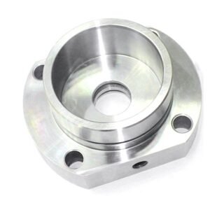

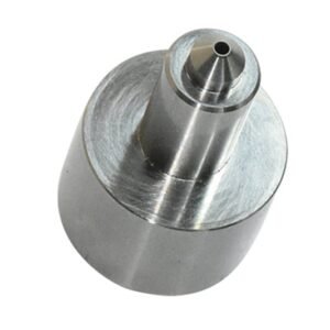


CNC Internal Grooving Services: Engineering Advantages
SUUXIANG reviews internal groove requirements before committing to a process route, aligning access, datum strategy, finishing, inspection, and revision control.
DFM Before Quotation
We review groove geometry, material, quantity, and critical requirements to identify manufacturability questions before quotation and production planning begin.
Datum-Aware Planning
Groove dimensions are considered against functional datums, mating features, and tolerance stack requirements rather than as isolated drawing callouts.
Tool Access Review
Internal diameter, groove location, depth, and wall clearance guide tool access, overhang, chip-control, and practical machining-route discussions.
EDM and Grinding Coordination
When conventional cutting is unsuitable, we assess EDM and grinding allowances alongside sequence, surface requirements, and downstream fitting needs.
Inspection Planning
CNC internal grooving services are planned around critical dimensions, accessible measurement methods, reporting needs, and the agreed inspection plan.
Revision Control
Drawing revisions, clarified requirements, and delivery information remain visible through project coordination to help prevent avoidable manufacturing mismatches.
Precision Component Families We Support
Drawing-driven process routes for grooved, critical, and mating features across custom parts, mold tooling, connector tooling, and die components.

CNC Machining Services
Precision CNC machining services for custom machined parts requiring controlled feature relationships, including grooves, bores, pockets, threads, and datum-driven dimensions. Process planning is reviewed against material, geometry, quantity, critical dimensions, and inspection requirements before production commitment.
Upload a Drawing
CNC Milling
Custom CNC milling services for prismatic and contoured components with pockets, slots, grooves, faces, and locating features. Tool access, clamping strategy, corner conditions, machining allowance, and datum sequence are reviewed to support the intended functional geometry.
Upload a Drawing
CNC Turning
Precision CNC turning services for cylindrical components with grooves, shoulders, threads, bores, and concentric features. The review considers turning access, groove geometry, runout relationships, material condition, and inspection references needed for the drawing-defined application.
Upload a Drawing
5-Axis Machining
5-axis CNC machining supports complex surfaces and multi-face features where reduced setups can help preserve positional relationships. SUUXIANG evaluates tool reach, fixture access, feature orientation, surface requirements, and inspection strategy before selecting this process route.
Upload a Drawing
Swiss & Micro Machining
Swiss machining and micro machining support small, slender, and detail-intensive components such as pins, shafts, micro-grooved parts, and connector features. Drawing review addresses feature stability, material behavior, tolerances, cutoff conditions, and practical inspection access.
Upload a Drawing
Wire & Sinker EDM
Wire EDM and sinker EDM services address narrow slots, internal corners, hardened features, deep ribs, fine grooves, and shapes unsuitable for conventional cutting alone. Electrode strategy, wire path, flushing conditions, allowance, and finishing requirements are reviewed by application.
Upload a Drawing
Precision Grinding
Precision surface and profile grinding supports controlled flatness, parallelism, profile relationships, and finished dimensions on hardened or precision-machined components. Grinding stock, datum references, heat-treatment sequence, wheel access, and inspection method should be defined before release.
Upload a Drawing
Mold Core Inserts & Mold Cavity Inserts
Precision mold core and cavity inserts are produced from customer drawings for molding tools requiring controlled parting, shutoff, cavity, core, cooling, or feature-detail geometry. CNC, EDM, grinding, fitting, material condition, and critical inspection points are planned around the specified insert function.
Upload a Drawing
Ejector & Ejection Components
Ejector pins, sleeves, and ejection components are configured for the mold’s movement, clearance, wear, and part-release requirements. Buyers should provide dimensions, material and hardness requirements, mating details, surface needs, and any groove or vent-related functional features.
Upload a Drawing
Core Pins, Guide & Locating Components
Core pins, guide pins, and locating components require controlled relationships with mating bores, inserts, or mold plates. SUUXIANG reviews fit intent, engagement length, groove details, hardness sequence, concentricity, and inspection datums from the drawing package.
Upload a Drawing
Wire EDM Services & Sinker EDM Services
Mold slides, lifters, gates, and accessories are manufactured as configurable tooling components rather than assumed standard stock items. The production route is defined around motion interfaces, shutoff surfaces, guide relationships, material treatment, wear areas, and fitting requirements.
Upload a Drawing
Connector Mold Components
Precision connector mold components support tooling features used to form connector housings, terminals, cavities, and mating details. Review focuses on fine geometry, pin and slot relationships, EDM requirements, material condition, critical dimensions, and traceable revision control.
Upload a Drawing
Stamping Die Components
Precision stamping die components support drawing-based punches, dies, inserts, guides, and related tool elements. Process planning considers profile geometry, clearance intent, wear surfaces, heat treatment, grinding stock, wire-EDM paths, and dimensional verification.
Upload a Drawing
Injection, MIM, CIM & Overmolding Tooling
Injection, MIM, CIM, and overmolding tooling components are evaluated within SUUXIANG’s verified production scope. Drawings should identify material, shrinkage-related interfaces, mold function, critical details, surface requirements, and any mating or insert conditions affecting manufacturability.
Upload a Drawing
Injection Mold Components for MIM, CIM & Overmolding
CNC machining materials are selected against the drawing, part function, machining features, heat-treatment needs, corrosion or wear considerations, and available material documentation. Confirm the specified grade, condition, substitute restrictions, and any material traceability requirement with the RFQ.
Upload a Drawing
Surface Finishes & Heat Treatment
Surface finishing and heat treatment are planned as part of the dimensional process route, not as isolated add-ons. Specify finish type, roughness or appearance criteria, hardness requirements, treatment sequence, masked areas, post-treatment grinding, and inspection expectations.
Upload a Drawing
Quality, Metrology & Documentation
Precision inspection, metrology, and quality documentation are aligned to the approved drawing and inspection plan. Define critical dimensions, datums, measurement methods, report format, material records, revision status, and any customer-specific traceability requirements before production begins.
Upload a Drawing
Prototyping & Low-Volume Production
Rapid prototyping and low-volume manufacturing support drawing-driven evaluation, bridge quantities, tooling trials, and controlled component releases. Provide the 2D drawing, 3D model when available, material, quantity, quality priorities, revision status, and target delivery date for review.
Upload a DrawingMaterials for CNC Internal Grooving Services

Alloy Tool Steel
A rigid choice for mold cores, inserts, and wear-focused tooling. Heat-treatment condition affects cutting load, burr control, and grinding allowance, so SUUXIANG reviews the specified grade and final hardness against the drawing.

Stainless Steel
Used for corrosion-conscious components, precision housings, and connector-related tooling. Its work-hardening behavior can influence tool access, chip evacuation, and internal-groove finish; material condition and surface requirements need early review.

Carbon Steel
A practical option for many custom machine parts, die components, and fixtures. Grade and heat-treatment sequence affect machinability and edge condition, particularly where narrow grooves require controlled chip removal and subsequent inspection.

Aluminum Alloys
Suitable for lightweight fixtures, prototypes, and machined structural components. The softer material can machine efficiently, but groove walls may require sharp tooling and chip-control planning to limit smearing and protect dimensional priorities.

Copper Alloys
Specified for conductive parts, electrical interfaces, and specialized connector applications. Ductility can increase burr and chip-packing risk in confined internal features, making groove dimensions, deburring expectations, and inspection criteria important RFQ inputs.
CNC Internal Grooving Services and Finishing Routes

CNC Internal Turning
Used for accessible bore grooves, seal seats and retaining features. Tool reach, insert clearance, chip evacuation and wall rigidity are reviewed to help control groove width, depth, position and surface condition.


Wire EDM Cutting
Considered for precise profiles, narrow internal features and hardened material conditions where a suitable wire path is available. The route is planned around start-hole access, corner geometry, finish requirements and inspection datums.

Sinker EDM Forming
Used when enclosed groove geometry or restricted access cannot be reached effectively by conventional cutting. Electrode design, spark-gap allowance, recast-layer considerations and subsequent finishing requirements are defined during review.

Precision Grinding
Selected for critical surfaces and controlled finishing after machining, heat treatment or EDM where applicable. Grinding stock, datum control, wheel access and the required inspection method are confirmed against the drawing.
Supporting Features for CNC Internal Grooving Services

Threads and Tapped Holes
Internal or external threads and tapped holes can be planned alongside groove features when callouts define thread standard, depth, datum relationship, material condition, and any gauging or functional-fit requirement.

Cross Holes
Radial, axial, or intersecting holes may support lubrication, venting, retention, or assembly. Their location relative to the internal groove, bore axis, and critical datums should be confirmed during drawing review.

Locating Features
Shoulders, pilot diameters, flats, keyways, and locating faces can establish repeatable assembly position. SUUXIANG reviews datum strategy, tolerance stack, and machining access so these features support the intended mating relationship.

Surface Finishing
Surface requirements for bores, grooves, sealing lands, or external faces should identify the relevant area and condition. The production plan can then consider machining, grinding, EDM, and post-process requirements appropriately.

Part Markings
Part numbers, revision identifiers, orientation marks, or customer-specified markings can be considered when their location, method, legibility, and impact on functional surfaces are defined in the approved drawing package.

Inspection Documentation
Inspection reports, material records, revision references, and packing labels can be matched to the order’s verified quality plan. Provide critical dimensions, reporting format, traceability needs, and delivery labeling requirements with the RFQ.
About SUUXIANG CNC Internal Grooving Services
SUUXIANG is the international-facing brand of Dongguan SuuXiang Precision Mold Co., Ltd., established in 2010 in Chang’an Town, Dongguan, Guangdong, China. XiaoCheng Huang is the founder and legal representative. We help global teams translate drawings and specifications into inspected custom CNC parts, precision mold components, connector-tooling components, and stamping-die components.
Our CNC internal grooving services are planned around the feature’s function, datum relationship, access limits, material condition, and inspection needs. Depending on the drawing, the route may combine CNC turning or milling with EDM, grinding, fitting, and controlled inspection rather than treating a groove as an isolated operation.
What distinguishes SUUXIANG is disciplined project communication before production commitments. We review critical dimensions, tolerance stack, groove geometry, machining allowance, tool or electrode strategy, heat-treatment sequence, and reporting requirements so the RFQ reflects the evidence needed for a responsible manufacturing decision.

CNC Internal Grooving Services: Reliable Feature Control
DFM and Datum Review
Before quotation, SUUXIANG reviews the drawing, 3D model, groove location, datum scheme, tolerance stack, material and application context. This identifies access constraints and critical dimensions so the proposed CNC internal grooving services route aligns with the part’s functional requirements.
- Confirm bore, groove-width and depth callouts
- Review datum references and inspection access
- Identify tolerance-stack and mating-part risks
- Clarify material, quantity and quality requirements

Machining and EDM Strategy
Internal grooves require a process route suited to bore access, feature geometry and material condition. SUUXIANG evaluates whether CNC turning or milling can reach the feature directly and when EDM may be relevant, while considering tool rigidity, chip evacuation and subsequent finishing needs.
- Assess tool access and practical overhang
- Plan machining sequence around heat treatment
- Evaluate EDM needs for restricted geometry
- Protect critical surfaces during intermediate operations

Grinding and Fitting Coordination
Where groove function depends on adjacent locating, sealing or assembly surfaces, machining cannot be considered in isolation. SUUXIANG coordinates machining allowance, grinding stock and fitting requirements to preserve relationships between the internal feature, bore, datum surfaces and mating components.
- Define allowance before finishing operations
- Coordinate groove location with adjacent surfaces
- Review edge condition and functional transitions
- Use mating context when it affects fit

Inspection and Revision Traceability
Inspection planning is established around the dimensions that matter to function, rather than a generic report. SUUXIANG keeps drawing revisions, measurement expectations and delivery information visible through production, helping sourcing and quality teams verify that final documentation matches the confirmed order requirements.
- Align inspection methods with critical dimensions
- Record applicable drawing revision information
- Confirm reporting needs before production
- Maintain clear communication on changes and delivery

Drawing-Review Controls for CNC Internal Grooving
A drawing-led workflow keeps critical groove requirements, process decisions, inspection needs, and revisions visible before production.
← Swipe left or right to view →
Controlled CNC Internal Grooving Services Workflow
Each drawing-based project is reviewed against its critical dimensions, process route, inspection needs, and delivery requirements before production proceeds.
Review the RFQ Package
We review drawings, models, quantity, application context, material requirements, target date, and inspection expectations to clarify the manufacturing scope before quotation.
Confirm Critical Requirements
DFM discussion identifies datums, critical dimensions, groove geometry, tool access, tolerance stack, surface requirements, heat-treatment sequence, and feasible inspection methods.
Plan the Process Route
The team selects an appropriate route across CNC turning or milling, internal grooving, EDM where required, grinding allowance, fitting, and revision-controlled work instructions.
Machine and Finish Features
Production follows the approved process plan, managing internal groove access, chip evacuation, electrode or wire path, finishing stock, and mating-feature relationships.
Inspect, Pack, Coordinate Delivery
Finished parts are inspected to the agreed plan, documented as required by the order, protected for shipment, and coordinated with visible revision and delivery information.
How to Start CNC Internal Grooving Services
A drawing-led workflow for reviewing groove requirements, confirming the process route, and moving into controlled production.
Submit Your Drawing Package
Provide 2D drawings, 3D models when available, material, quantity, groove dimensions, critical tolerances, surface requirements, inspection needs, and target delivery date.
Review DFM and Quotation
Review proposed machining access, datum strategy, tool or EDM considerations, inspection approach, revision status, commercial scope, and any manufacturability questions before commitment.
Approve First-Article Requirements
Confirm sampling or first-article expectations where applicable, including critical dimensions, measurement methods, reporting format, acceptance criteria, and approved drawing revision.
Release Controlled Production
Proceed through the confirmed CNC internal grooving services process, with appropriate machining, finishing, inspection, traceability, and delivery coordination aligned to the verified order plan.
CNC Internal Grooving Services: Certificates and Quality Evidence

Customer Feedback on CNC Internal Grooving Services
Customer testimonial pending written approval and verification against the applicable drawing revision, inspection record, and documented project outcome before publication.
Project outcome summary pending customer authorization and evidence review. SUUXIANG will publish only verified details tied to the approved RFQ, production records, and inspection documentation.
Customer feedback will be added after approval confirms the quoted outcome, relevant quantity, dimensional requirements, and inspection scope. No performance figures are published without supporting project evidence.
CNC Internal Grooving Services FAQ
Practical answers for engineering, sourcing, and quality teams preparing a drawing-based grooving RFQ.
What files should I send for cnc internal grooving services?
What is the MOQ for cnc internal grooving services?
How long do cnc internal grooving services take for samples and production orders?
Can you machine internal grooves after heat treatment?
What inspection reports are available for internal groove dimensions?
How do you control burrs, tool marks, and chip damage inside a groove?
Can SUUXIANG ship cnc internal grooving services parts internationally?
How are payment terms and drawing confidentiality handled?
Complete Buyer’s Guide to cnc internal grooving services
Use this decision framework to specify groove geometry, evaluate capable suppliers, control cost and lead time, and avoid RFQ mistakes that compromise sealing, retention, assembly, or inspection outcomes.
1. What Are cnc internal grooving services?
One internal groove is a controlled channel machined on a bore’s inside diameter by a CNC turning tool. It can seat an O-ring, retain a ring, provide assembly clearance, meter or direct fluid, or locate a mating component.
Four similar operations serve different geometries: boring enlarges or corrects the bore; internal threading forms a helical thread; external grooving cuts the outside diameter; and face grooving cuts an end face. Internal grooving instead controls a local recess within the bore, usually by radial tool entry.
Two constraints make DFM essential: the tool must reach the feature, and chips must leave the confined cut without damaging the groove. Drawing review should therefore establish bore entry, groove width and depth, corner radii, datum location, tool clearance, and inspection access before a CNC internal grooving services RFQ is released. Reference: https://dzmaking.com/grooving-in-cnc-machining
2. From Manual Lathes to CNC Control
1 manual-lathe setup traditionally relied on a fixed workholding position, hand-set stops, and a form tool whose profile governed the groove. Results could be acceptable, but repeat production depended heavily on operator setup, tool condition, and recorded methods.
2 CNC turning-center axes made groove location, feed, depth, and dwell programmable instead of being recreated at each setup. Indexable grooving inserts separate replaceable cutting edges from the holder, while live tooling can consolidate related drilled or milled features when the part and machine configuration permit it.
3 drawing-controlled controls matter more to a buyer than the machine label. A controlled CNC route can retain the program revision, tool and insert selection, setup datum, in-process checks, and digital inspection results, making deviations easier to investigate and repeat orders easier to review. For cnc internal grooving services, request the inspection plan and revision-controlled documentation alongside the quotation.
3. Types of cnc internal grooving services
CNC internal grooving services should be selected by feature function, not by a generic bore-groove label. The required tool approach, chip path, and inspection datum change substantially with groove location and profile.
Radial And Face Grooves
Radial ID grooves are recessed rings cut inward from a bore wall, commonly used for O-rings, retaining rings, and seal seats. Call out bore datum, groove width, diameter, depth, corner radii, and axial location.
Internal face grooves run radially across an internal end face for valve seats, flange sealing features, or stepped housings. Specify face datum, radial start and finish diameters, depth, and the clearance needed for the holder to enter and retract.
Repeated And Micro Grooves
Multi-groove patterns repeat rings at controlled pitch in connector sleeves, retention features, or fluid-control parts. Define groove count, pitch from one datum, individual geometry, and whether cumulative pitch error is critical.
Narrow micro-grooves require a small-bore bar with limited stiffness and chip space. State the minimum bore diameter, groove width, depth, bottom radius, material condition, and whether burr limits apply at both groove edges.
Undercut And Profile Grooves
Undercuts extend behind a bore shoulder, creating clearance or retention where a straight radial tool cannot fully form the feature. Show the throat opening, hidden diameter, axial reach, and tool-relief geometry in section view.
Profile or radius-bottom grooves use a formed or interpolated contour for seals and stress-sensitive transitions. Dimension the profile from functional datums and provide the required radius, blend limits, surface requirement, and mating-component context.
4. Materials for cnc internal grooving services
Seven material families demand different cutting loads and chip-control plans inside a confined bore. Grade, temper or heat-treatment condition, and stock form should be fixed before SUUXIANG reviews cnc internal grooving services.
| Material | Machinability | Typical Applications | Internal-Grooving Considerations | Buyer Requirement |
|---|---|---|---|---|
| Aluminum | High | Housings | Burr control; chip adhesion | Alloy and temper |
| Brass | High | Fittings | Good finish; short chips | Grade and lead restriction |
| Carbon steel | Medium | Mechanical parts | Higher force; manage chips | Grade and condition |
| Stainless steel | Medium-low | Corrosion-resistant parts | Work hardening; tool wear | Grade and annealed state |
| Tool steel | Low | Mold components | Wear; heat-treatment sequence | Grade, hardness, condition |
| Titanium | Low | Lightweight components | Heat and chip control | Grade and mill condition |
| Engineering plastics | Variable | Insulators | Heat, rollover, stringy chips | Polymer and filler content |
Cutting Behavior And Geometry
Aluminum and brass usually permit lower cutting force and clean finishes, but ductile aluminum can leave burrs. Carbon steel, stainless steel, tool steel, and titanium raise heat, wear, or work-hardening risk; narrow deep grooves need conservative tool reach and chip evacuation.
Buyer Material Definition
Each RFQ should state the exact grade, condition, heat-treatment state, and any material certificate requirement. Engineering plastics require polymer grade and filler content because heat sensitivity, stringy chips, and edge rollover can alter the achievable groove profile.
5. Groove Geometry and DFM Options
Two linked decisions—functional fit and cutter access—govern a practical internal groove. Specify geometry from the mating function, then allow a drawing review to confirm a stable cnc internal grooving services route.
Size The Cutting Envelope
Three dimensions require joint review: bore diameter, groove width, and radial depth. A narrow, deep groove may require a slender bar, reducing rigidity and chip evacuation.
One stated minimum bottom radius can prevent an unsuitable sharp-corner requirement. Add corner relief only where the mating part truly needs it; relief increases tool-path and inspection considerations.
Locate From Functional Datums
One axial datum should control groove location when assembly position is critical. Dimensioning from an unrelated face can add tolerance stack and make verification less direct.
Two or more grooves need explicit center-to-center spacing and a defined datum origin. State whether location, width, depth, or runout is the critical requirement.
Make The Drawing Reviewable
A sectional view should show the complete groove profile, bore, depth, bottom radius, and adjacent shoulders. Call out surface finish and tolerances only on functional surfaces.
One note should identify acceptable alternatives, such as a larger radius or adjusted relief, with its functional limit. Include mating-component context and the inspection method when those choices affect acceptance.
- Show datum features and measurement direction
- Identify blocked tool access or blind-groove limits
- State allowed geometry alternatives before release
6. Quality Factors Inside the Bore
Two internal grooves with identical width can perform differently when their datum relationship, edge state, or debris condition changes. Usable quality must be specified and inspected inside the actual bore.
Dimensional Relationships
Three controls govern function: groove width, depth, and axial position. Relate each to a defined datum, not an assumed bore edge.
One concentricity or runout requirement should identify the controlling bore axis. Thin remaining walls also need a stated minimum thickness.
Surface And Edges
Two surfaces require separate acceptance criteria: groove floor and flanks. Define finish where sealing, retention, or mating contact makes it functional.
One edge-break requirement prevents unspecified sharp edges from becoming a burr-removal dispute. Cleanliness criteria should address chips, abrasive residue, and trapped coolant.
Inspection Evidence
Small diameters and deep bores restrict probe access, viewing angle, and repeatable seating. Agree the measurement method before production, especially where a contact probe cannot reach.
First-article evidence should connect each critical result to the approved drawing revision. Acceptance criteria should state sample quantity and disposition of nonconforming results.
- First-article report with actual values
- Instrument and measurement setup
- Bore datum and groove location
- Surface, burr, and cleanliness criteria
7. Choosing cnc internal grooving services Suppliers
A drawing-based approval should test the supplier’s process evidence, not its machine list. For cnc internal grooving services, ask how the quoted bore, groove, material condition, and inspection datum will be controlled.
Machine And Tooling Fit
First, confirm the turning center, chuck or collet workholding, bore reach, and part-support method for the actual drawing. Ask for the boring-bar diameter, overhang, insert width, chip-control approach, and whether the tool can clear the groove without holder interference.
Material And Process Control
Second, require material identification tied to the order and clarification of heat-treatment sequence before machining begins. Ask which dimensions are checked in process, how tool wear is monitored, and when a first-off part triggers adjustment or customer review.
Inspection And Communication
Third, match inspection evidence to critical dimensions, including the groove width, depth, location, and datum relationship. Ask whether the supplier can provide agreed reports, revision-controlled documentation, prototype feedback, and a single technical contact through low-volume release.
8. Common Internal-Grooving RFQ Mistakes
Eight recurring RFQ gaps can turn a feasible internal groove into an avoidable delay, concession, or inspection dispute. Resolve them in the released drawing and inspection plan before supplier selection.
Define The Groove Section
A section view must state groove width, depth or diameter, corner radius, wall profile, and axial location. Missing geometry forces assumptions about tool form, chip clearance, and functional fit.
Establish Datums And Tolerances
One datum scheme should locate every groove relative to the bore, face, or functional feature. Ambiguous plus-or-minus tolerances can hide runout, location, or form requirements; add GD&T where function depends on them.
Confirm Process Conditions
A specified material grade, heat-treatment condition, and surface requirement affect cutting strategy and achievable finish. Narrow, deep geometry may restrict tool access; provide minimum bore diameter, depth, and allowable relief or redesign options.
Release Quality Requirements
A burr limit, edge-break instruction, and inspection method prevent disagreements after machining. State whether visual examination, pin gauges, bore measurement, or a report is required, then compare quotations against that same scope rather than price alone.
9. Launching a Controlled Prototype Order
A controlled prototype begins with one released drawing package, functional context, and named owners. For cnc internal grooving services, freeze the bore datum, groove function, material condition, and inspection decision before material is cut.
Review The Drawing Package
First, engineering should identify groove width, depth, corner condition, datum references, mating part, and CTQ dimensions. Procurement should transmit the current revision, 3D model when available, quantity, and requested date as one controlled package.
Close DFM Before Machining
Before release, SUUXIANG can return DFM feedback on tool access, chip evacuation, workholding, EDM or grinding allowances, and inspection access. Supplier quality should record each accepted deviation or clarification against the drawing revision.
Approve Samples And Pilot
At sample approval, compare measured results with the agreed inspection plan and functional fit evidence. For connector tooling, mold inserts, stamping-die components, and low-volume parts, use a defined pilot quantity before production release.
Control Changes To Release
After approval, engineering owns technical revisions, procurement owns the purchase-order revision, and quality owns acceptance criteria. No changed groove geometry, heat treatment, or reporting requirement should enter production without written revision control.
10. cnc internal grooving services Cost Drivers
1 CNC internal-grooving quote begins with setup: programming, workholding, tool selection, and first-piece verification are spread across the order quantity. Material machinability, bore diameter-to-depth access, groove count, tolerance, finish, inspection reporting, and any heat treatment or secondary operation then determine cycle time and risk.
2 Cost can fall when the drawing identifies functional datums, consolidates compatible internal features, and avoids unnecessary tight tolerances or cosmetic finishing inside inaccessible bores. Allow time for DFM questions, sample approval, and revision release before committing expedited delivery.
| Quantity tier | Setup share | Major cost drivers | Planning focus |
|---|---|---|---|
| 1–10 prototypes | High per part | Custom tool reach, restricted chips, first-article inspection | Confirm process route and approval timing |
| 11–50 pieces | Moderate | Material, groove count, tolerance, secondary operations | Standardize datums and consolidate features |
| 51–200 pieces | Lower | Cycle time, insert wear, inspection frequency | Release stable revision before production |
| 201+ pieces | Lowest setup share | Tool-life control, batch inspection, delivery scheduling | Review repeatability and lot requirements |
Start Your CNC Internal Grooving Services RFQ
Submit your drawing, model, material, quantity, critical dimensions, inspection requirements, and target date for a focused DFM-led review.