
Cross-Hole Machining Services for Precision Parts
Submit your drawing for cross-hole machining services planned around critical dimensions, DFM, inspection requirements, and revision control.
Representative Components for Cross-Hole Machining Projects





Related Product Catalogue and Quotation


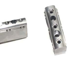
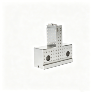
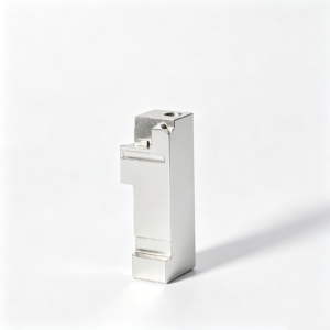
Why Choose SUUXIANG for Cross-Hole Machining Services
A drawing-led workflow for difficult intersecting holes, controlled finishing, and inspection-ready communication.
Drawing-Led DFM Review
We review datums, intersecting features, critical dimensions, and tolerance-stack risks before quotation so the proposed route reflects the drawing.
Tool Access Planning
Machining access, drill approach, chip evacuation, and fixture constraints are considered early to identify practical risks around complex hole intersections.
EDM Route Decisions
Where conventional tools cannot reliably reach the feature, electrode strategy or wire paths can be assessed against geometry and finish requirements.
Grinding Allowance Control
Grinding stock and sequence are planned around heat treatment, functional surfaces, and critical dimensions requiring a controlled final machining route.
Inspection-Ready Planning
Inspection priorities are defined from the drawing, including critical dimensions, datum references, measurement methods, and reporting expectations for the order.
Revision Traceability
Visible revision control and traceable project communication help keep drawing changes, manufacturing questions, inspection requirements, and delivery coordination aligned.
Drawing-Driven Machining for Critical Components
Select the process or component family that fits your drawing, critical dimensions, material requirements, inspection expectations, and production stage.

CNC Machining Services
Precision CNC machining services for custom machined parts, mold components, and tooling features defined by your drawings. Reviews focus on material, datums, critical dimensions, machining access, surface requirements, and inspection needs before a process route is proposed.
Upload a Drawing
CNC Milling
Custom CNC milling services for prismatic parts, plates, inserts, pockets, contours, and precision interfaces. SUUXIANG evaluates tool access, clamping strategy, corner conditions, machining allowance, and tolerance relationships against the supplied drawing and model.
Upload a Drawing
CNC Turning
Precision CNC turning services for rotational parts such as pins, bushings, sleeves, shafts, and threaded features. Drawing review considers concentricity, runout, datum selection, wall thickness, material condition, and any secondary milling, EDM, or grinding operations required.
Upload a Drawing
5-Axis Machining
5-axis CNC machining supports multi-face and contoured components where fewer setups can protect positional relationships. Feasibility depends on geometry, tool reach, workholding, material, critical tolerances, and the inspection method defined for the project.
Upload a Drawing
Swiss & Micro Machining
Swiss machining and micro machining support small, detailed components with demanding diameter, feature, and handling requirements. Review drawings early for slender-feature stability, burr control, material behavior, cross-hole access, critical dimensions, and practical measurement methods.
Upload a Drawing
Wire EDM Services & Sinker EDM Services
Wire EDM and sinker EDM services address narrow slots, sharp internal features, hardened materials, and geometries with limited conventional tool access. Process planning considers wire path or electrode strategy, flushing, surface condition, recast-layer requirements, and downstream fitting or grinding.
Upload a Drawing
Precision Grinding
Precision surface and profile grinding supports controlled flatness, parallelism, profile accuracy, and finished dimensions on applicable parts. SUUXIANG reviews grinding stock, heat-treatment sequence, datum control, wheel access, surface requirements, and inspection criteria before production.
Upload a Drawing
Mold Core & Cavity Inserts
Precision mold core inserts and mold cavity inserts are manufactured from drawing-defined geometry, material, heat treatment, cooling features, and mold interfaces. Planning coordinates CNC machining, EDM, grinding, fitting, and inspection around shutoff areas, datum relationships, and critical molded-part features.
Upload a Drawing
Ejector & Ejection Components
Ejector pins, sleeves, and ejection components are reviewed for diameter control, clearance relationships, hardness requirements, surface condition, and motion within the mold assembly. Provide mating-part context where ejection alignment, wear, or component interchangeability is critical.
Upload a Drawing
Core Pins, Guide & Locating Components
Core pins, guide pins, and locating components require controlled relationships to mating bores, inserts, and assembly datums. SUUXIANG reviews fit intent, material and heat-treatment requirements, geometry, surface needs, and the dimensions that must remain stable through production.
Upload a Drawing
Slides, Lifters, Gates & Mold Accessories
Mold slides, lifters, gates, and accessories are produced as configurable drawing-based components, not assumed stock items. Project review addresses travel and interface geometry, shutoff conditions, wear surfaces, cooling or vent features, fitting requirements, and inspection priorities.
Upload a Drawing
Connector Mold Components
Precision connector mold components support tooling features where fine pitch, repeatable alignment, insert relationships, and cavity detail affect connector performance. Drawings should identify critical dimensions, material and treatment requirements, EDM features, mating parts, and inspection expectations.
Upload a Drawing
Stamping Die Components
Precision stamping die components are evaluated for working profiles, clearance relationships, guide features, material condition, heat treatment, grinding stock, and assembly interfaces. SUUXIANG coordinates machining, EDM, grinding, and inspection according to the documented die-component requirements.
Upload a Drawing
Injection, MIM, CIM & Overmolding Tooling
Injection, MIM, CIM, and overmolding tooling work is assessed within verified production scope. Supply molded-part requirements, resin or feedstock context, tooling layout, shrinkage assumptions, critical features, material specifications, and quality expectations for a responsible DFM discussion.
Upload a Drawing
Machining Materials
CNC machining materials are selected against drawing requirements, functional loads, corrosion exposure, machinability, heat-treatment sequence, and finish needs. State the specified grade or approved alternative, material documentation requirements, and any application constraints before quotation.
Upload a Drawing
Surface Finishes & Heat Treatment
Surface finishing and heat treatment are planned around dimensional change, wear, corrosion resistance, appearance, and post-treatment machining or grinding needs. Identify the required treatment, finish, masking areas, critical dimensions, hardness expectations, and relevant acceptance criteria.
Upload a Drawing
Quality, Metrology & Documentation
Precision inspection, metrology, and quality documentation are defined by the drawing and agreed inspection plan. Identify critical-to-quality dimensions, datum scheme, sampling or reporting needs, material records, revision level, and any customer-specific traceability requirements before production.
Upload a Drawing
Prototyping & Low-Volume Production
Rapid prototyping and low-volume manufacturing support drawing-based validation, bridge quantities, tooling trials, and controlled production needs. Provide quantity, target date, revision status, material, quality priorities, and intended application so process, inspection, and delivery planning can be assessed.
Upload a DrawingMaterials Considered During Cross-Hole Machining Review

Alloy Tool Steels
Common for mold cores, cavity inserts, slides, and wear-critical tooling. Grade and heat-treatment condition influence drilling response, EDM sequence, grinding stock, and burr-control planning around intersecting holes.

Stainless Steel Grades
Often specified for corrosion-resistant mold components, connector tooling, and precision machine parts. Alloy family, hardness, and hole geometry affect chip evacuation, work-hardening risk, surface requirements, and finishing strategy.

Carbon Steel Grades
Used in fixtures, die components, structural precision parts, and selected tooling applications. Material condition influences machining allowance, cross-hole deburring approach, protective finish needs, and dimensional stability after heat treatment.

Aluminum Alloy Grades
Suitable for lightweight fixtures, prototype parts, and selected production components where stiffness-to-weight matters. Alloy temper affects thread strength, burr formation at hole intersections, surface finish, and handling during inspection.

Copper Alloy Materials
Considered for conductive inserts, electrical tooling features, and specialized wear applications. Material grade affects tool selection, edge condition, deformation risk, and whether cross-hole geometry requires dedicated support during machining.
Cross-Hole Machining Services: Process Routes

CNC Milling
CNC milling establishes accessible cross-drilled features, pockets, locating faces and datum references. Tool approach, chip evacuation and intersecting-hole geometry are reviewed to reduce burr risk and preserve the surfaces used for subsequent operations.

Wire EDM
Wire EDM can form profiles, narrow slots and hard-material features where conventional cutter access is limited. The wire path, start-hole position and remaining stock are planned against the drawing’s functional edges and tolerance requirements.

Sinker EDM
Sinker EDM supports enclosed cavities, sharp internal geometry and difficult intersections that require a shaped electrode. Electrode strategy, spark allowance and finishing requirements are evaluated before committing to the route for a drawing-based component.

Precision Grinding
Precision grinding refines critical diameters, flats and reference surfaces after machining or heat treatment. Grinding stock, workholding and datum sequence are considered to support dimensional control where mating fits or measurement repeatability matter.

Fitting Operations
Controlled fitting addresses component interfaces, movement and assembly relationships after the primary machining steps. The work is guided by documented functional requirements, with attention to contact surfaces, clearance expectations and any specified mating context.

Final Inspection
Final inspection follows the agreed drawing revision and inspection plan for critical dimensions, surfaces and hole relationships. Measurement methods and reporting needs should be defined early so the required evidence aligns with the order requirements.
Specify Component Additions and Identification Requirements

Locating Features
Dowel holes, locating flats, keyways, or reference features can support repeatable orientation during assembly, molding, or inspection. Their datum relationship, fit class, and sequence relative to cross-hole machining should be defined on the drawing.

Threaded Inserts
Threaded inserts may be considered where repeated fastening, material limitations, or serviceability affect the joint design. Provide insert type, thread, installation method, pull-out expectations, and any required clearance from intersecting holes or thin walls.

Alignment Pins
Precision pins can establish component position between mating parts, fixtures, or mold elements. Specify pin diameter, fit, engagement depth, material, hardness requirements, and whether holes are machined before or after heat treatment.

Part Markings
Laser marking, stamped identification, revision marks, or orientation references can help control assembly and traceability. Identify marking content, location, character limits, surface condition, and whether the mark must remain legible after finishing or use.

Packaging Labels
Packaging labels can identify part number, revision, quantity, lot, and handling requirements for receiving and inspection. Share your labeling format, barcode needs, packaging protection expectations, and documentation requirements before production planning.
About SUUXIANG Cross-Hole Machining Services
Established in 2010 and based at 2nd Floor, Sanhe Industrial Park, Chang’an Town, Dongguan, Guangdong, China, SUUXIANG is the international-facing brand of Dongguan SuuXiang Precision Mold Co., Ltd., founded and legally represented by XiaoCheng Huang. We help global engineering, sourcing, and quality teams turn drawings into inspected custom CNC parts, precision mold components, connector tooling, and stamping-die components.
Our cross-hole machining services are planned from the drawing outward. Before quotation and production commitments, we review critical dimensions, datums, tolerance stack, tool access, chip evacuation, burr-control expectations, material condition, and the need for EDM, grinding, fitting, or dedicated inspection methods.
What differentiates SUUXIANG is disciplined project control across CNC milling and turning, multi-axis machining, EDM, grinding, fitting, and inspection. We keep revision requirements, process decisions, and inspection expectations visible so buyers can evaluate manufacturability and align production evidence with their order requirements.

Cross-Hole Machining Services: Planning Difficult Features
Datum and DFM Review
SUUXIANG reviews the drawing model, datums, intersecting-hole locations, tolerance stack and functional interfaces before committing to a route. This clarifies which dimensions govern the feature and where access, clamping or measurement may introduce risk.
- Confirm primary, secondary and tertiary datums
- Identify critical hole-to-hole relationships
- Review tool approach and workholding access
- Flag tolerance-stack risks before quotation

Machining and EDM Strategy
Intersecting bores may require a staged plan rather than a single drilling operation. SUUXIANG evaluates machining direction, chip evacuation, tool reach, wire path and electrode access to select a practical route for the specified geometry and material condition.
- Sequence intersecting features around datum control
- Assess chip evacuation at internal intersections
- Determine when EDM access is appropriate
- Protect functional edges during intermediate operations

Grinding Allowance Planning
Where hardened surfaces or precise locating features require grinding, stock must remain after earlier operations without compromising the cross-hole relationship. The review considers heat-treatment sequence, grind access and the dimensions that should be finalized after grinding.
- Define stock for post-heat-treatment grinding
- Check cross-hole position against ground datums
- Review wheel access and relief requirements
- Align finishing order with critical dimensions

Inspection Plan Alignment
Inspection planning connects the drawing’s critical dimensions to practical measurement methods before production begins. SUUXIANG discusses reporting needs, datum setup, feature accessibility and revision status so final documentation aligns with the agreed inspection plan.
- Identify dimensions requiring documented verification
- Establish inspection datums and measurement approach
- Confirm reporting and traceability requirements
- Keep drawing revisions visible through delivery

Cross-Hole Machining Services Beyond Generic CNC Quoting
Compare the planning, inspection, and project visibility needed for drawing-driven cross-hole features.
← Swipe left or right to view →
Cross-Hole Machining Services: From Drawing to Inspection
A drawing-led workflow that aligns feature access, process routing, critical dimensions and documented inspection before shipment coordination.
Review RFQ Inputs
We review drawings, models, material, quantity, application context, delivery target and reporting needs, identifying missing information before quotation or production commitments are made.
Define DFM Priorities
Critical dimensions, datums, intersecting-hole geometry, tool access, burr-control expectations, surface requirements and tolerance stack risks are discussed to establish a manufacturable inspection plan.
Route Manufacturing Processes
The team selects an appropriate sequence across CNC machining, EDM, grinding, heat-treatment coordination and fitting, allowing stock and access requirements to remain visible.
Machine Critical Features
Approved revisions guide machining of cross-hole features and related geometry, with process choices adapted to the drawing, material condition, electrode needs and grinding allowance.
Inspect, Pack, and Coordinate Delivery
Parts are inspected against the agreed plan, documentation is matched to order requirements, and packing and shipment coordination proceed with revision traceability kept visible.
Start Your Cross-Hole Machining Project
Move from drawing review to controlled production with the requirements, decisions, and inspection expectations visible at each stage.
Submit Your Drawing Package
Provide 2D drawings, 3D models when available, material, quantity, delivery target, critical dimensions, surface requirements, and any mating-component context that affects the hole feature.
Review DFM and Quotation
Review machining access, datum strategy, intersecting-hole risks, burr-control approach, EDM or grinding needs, inspection method, and the proposed process route before commitments are finalized.
Approve Production Details
Confirm the quotation, revision level, material and heat-treatment requirements, quality documentation, and sample or production details so the manufacturing plan matches your order requirements.
Coordinate Inspection and Delivery
Production follows the agreed process plan, with inspection against the verified requirements and delivery coordination aligned to the approved revision, reporting needs, and schedule.
Quality and Compliance Evidence for Your Project
Customer Evidence Publication Policy
SUUXIANG publishes customer feedback only after customer approval and verification against the applicable project record.
Published project evidence must identify the relevant drawing scope, inspection requirements, and verified outcome without disclosing confidential information.
Until customer-approved evidence is available, SUUXIANG does not present placeholder testimonials as project proof.
Cross-Hole Machining Services FAQ
Practical answers for drawing-based sourcing, review, inspection, and project coordination.
What is the minimum order quantity for cross-hole machining services?
Can SUUXIANG review cross-hole machining services before quotation?
Can you make samples before a larger cross-hole machining services order?
What affects lead time for an intersecting-hole CNC part?
What inspection reports are available for cross-hole machining services?
How are burrs at intersecting holes controlled?
Can SUUXIANG ship cross-hole machining services orders internationally?
How are drawings, payment terms, and design revisions handled?
The Complete Buyer’s Guide to cross-hole machining services
Use this decision framework to assess process feasibility, tolerances, burr control, inspection, supplier capabilities, and cost drivers—while avoiding drawing, DFM, and sourcing mistakes that can delay precision CNC projects.
1. What Are cross-hole machining services?
Two or more drilled, bored, or milled passages that intersect within a workpiece define cross-hole machining services. In drawing-based CNC parts, the intersection may control fluid or air flow, a fastener path, a retention feature, assembly clearance, or access to another internal feature.
One intersection creates a discontinuity in the cutting path: the drill can break through into an existing bore, leave a burr at the crossing, and release chips into a passage that is difficult to clean. Diameter alone is therefore insufficient; positional relationship to datums, intersection location, edge condition, surface requirement, and allowable obstruction can all be functional.
Three questions should be resolved before quotation: what must pass through the feature, what mating part or seal depends on it, and how will acceptance be verified? SUUXIANG reviews the drawing, model, material, critical dimensions, and inspection expectations to identify a suitable CNC, EDM, grinding, deburring, and inspection route within the verified project scope.
2. Evolution of Cross-Hole Machining
Before CNC, cross holes were commonly produced by manually locating and drilling one feature at a time, then using secondary deburring to remove burrs created where passages broke through. Each re-clamp introduced another opportunity for position variation, and intersecting passages were difficult to inspect beyond accessible entrances.
From the 1950s onward, numerical control—and later CNC—made programmed positioning and repeatable tool paths practical for production machining. Multi-axis positioning can reduce handling by reaching features from more than one orientation within a controlled setup, while probing supports datum confirmation before cutting.
Today, controlled coolant delivery helps evacuate chips from demanding hole intersections, and inspection plans can link critical hole location, diameter, breakout condition, and burr acceptance to specified datums. For buyers of cross-hole machining services, the meaningful advance is not automation alone: it is a documented route from drawing revision through setup, machining, deburring, and traceable verification.
3. Types of cross-hole machining services
Six geometries require different access, burr-control, and datum plans. Select cross-hole machining services from the intersection function and drawing evidence.
| Type | Typical Function | Drawing Priority |
|---|---|---|
| Perpendicular drill | Venting | Datums; burr side |
| Angled intersection | Lubrication | Angle; intersection |
| Hole into bore | Pin or feed | Bore finish |
| Deep intersection | Internal flow | Depth; wall |
| Threaded port | Connection | Thread; seal face |
| Cooling passages | Thermal control | Circuit; test |
Perpendicular And Angled Holes
Two layouts are 90° cross drills and specified-angle intersections. They suit vents, retention, or lubrication; thin exit walls increase breakout-burr and drill-walk risk.
At drawing release, provide angle, datum-based intersection location, diameters, burr direction, and communication requirement.
Bore And Deep-Passage Intersections
Two cases are radial holes entering finished bores and holes intersecting deep axial passages. They support pins or flow; internal burr access and wall breakthrough govern sequencing.
At RFQ, state bore finish, passage depth, remaining wall, allowable obstruction, and inspection method.
Threaded And Fluid Ports
Two port types are threaded cross ports and intersecting cooling passages. Threads near intersections can tear or trap chips; fluid circuits require connectivity and cleanliness criteria.
At RFQ, specify thread standard and class, seal face, port orientation, pressure medium, and leak-test criterion.
4. Materials for Cross-Hole CNC Parts
For cross-hole machining services, the material controls chip evacuation, burr formation, heat load, and the finishing route. A drawing review should match the bore intersection to the material’s stiffness, ductility, and expected production quantity.
| Material Family | Cross-Hole Challenge | DFM Consideration | Suitable Context |
|---|---|---|---|
| Aluminum alloys | Burrs; chip packing | Support thin walls | Housings, fixtures |
| Carbon and alloy steels | Heat; drill wear | Leave grinding stock | Mold and die parts |
| Stainless steels | Work hardening | Use stable tool access | Corrosion-resistant components |
| Brass | Rolled exit burrs | Specify edge break | Connector components |
| Copper alloys | Stringy chips | Plan chip evacuation | Electrical interfaces |
| Engineering plastics | Deflection; feathering | Use backing support | Insulators, prototypes |
| Hard or heat-resistant alloys | High wear and heat | Review route before release | High-load components |
Chip Control And Burrs
Aluminum and brass usually cut freely but can leave rolled burrs at the hole exit or intersection. Copper alloys may form stringy chips, while engineering plastics require support to prevent deformation and feathered edges.
Heat, Wear, And Finish
Alloy steels and stainless steels increase heat and tool wear, especially where a cross-hole interrupts chip flow. Hardened or heat-resistant alloys may need staged drilling, controlled coolant, EDM consideration, and a defined deburring method.
Material Details For RFQs
The RFQ should state the exact grade, supply condition, hardness or heat-treatment sequence, plating, and surface restrictions. These inputs determine machining allowance, tool selection, inspection timing, and realistic cost comparison.
5. Cross-Hole Design and Customization Options
Two drawing views should define each hole’s axis, intersection location, and datum references. One RFQ should separate functional flow, fastening, or sealing requirements from appearance-only finishing.
| Feature | Functional Specification | Avoid |
|---|---|---|
| Blind cross-hole | Depth from datum; drill point allowance | Assuming a flat bottom |
| Threaded port | Standard, class, engagement length | Threading through burrs |
| Sealed intersection | Seal land and finish requirement | Calling all surfaces polished |
Define The Hole Network
Diameter pairs, intersection angles, and blind-versus-through conditions should be dimensioned from functional datums. A section view prevents ambiguity at concealed intersections.
One connector-tooling or mold drawing should state counterbore depth, chamfer size, thread standard, and usable thread length. Specify a plug, port, or mating component when it governs access.
Specify Function Before Finish
Sealing features require the bore finish, edge-break condition, plug geometry, and pressure medium to be identified. Corrosion protection must name the finish system and any masked surfaces.
Cosmetic polishing cannot substitute for a controlled sealing land or deburred intersection. Cross-hole machining services should receive functional surfaces and cosmetic surfaces as separate requirements.
Control Without Overconstraining
Critical tolerances belong on diameter, true position, intersection depth, and surface finish only where assembly demands them. General tolerances can govern noncritical external features.
Prototype, stamping-die, and mold designs should allow a feasible tool path, EDM access, and deburring strategy. SUUXIANG can review drawing priorities before selecting machining, EDM, grinding, and inspection steps.
6. Quality Elements in cross-hole machining services
A usable intersecting-hole feature is defined by measurable function, not appearance. For cross-hole machining services, the drawing should connect each critical condition to a datum, limit, inspection method, and acceptance criterion.
Location And Alignment
True position and angularity control whether passages intersect at the intended volume. Specify datum references, basic dimensions, and any concentricity requirement only where a common axis affects assembly or flow.
Breakthrough And Cleanliness
Breakthrough edges require a stated burr limit and edge-break size; ‘remove sharp edges’ is too ambiguous for a critical port. Define allowable chips, embedded debris, or contamination and the cleaning or visual-inspection acceptance method.
Functional Surface Requirements
Wall thickness around the intersection must retain the drawing minimum after machining and finishing. Call out bore finish, thread class or gauging method, and—where relevant—leak-test pressure, medium, duration, or flow-performance criteria.
Inspection Plan
First-article and in-process checks should reference the drawing-defined datum scheme, not convenient machine surfaces. SUUXIANG can align CMM, pin-gauge, thread-gauge, borescope, surface, or functional-test evidence with the order’s verified inspection plan.
7. Choosing cross-hole machining services Suppliers
Two supplier responses to the same drawing can reveal more than a capability list. For cross-hole machining services, evaluate the written review, risk ownership, and evidence proposed before comparing unit price.
| Evaluation Area | Question Before PO | Evidence To Request |
|---|---|---|
| DFM | How are intersecting-hole risks resolved? | Marked-up drawing |
| Material | How is specified material linked to the order? | Traceability record |
| Deburring | Which method reaches internal intersections? | Process description |
| Inspection | Which dimensions are reported? | Sample report |
Test The DFM Response
One useful review identifies intersecting-hole burr traps, tool access, datum conflicts, and the proposed sequence. Ask which features require EDM, reaming, grinding, or a design change.
Two documents should be returned: marked-up drawing comments and a revision-controlled process plan.
Verify Controls And Evidence
Three control points deserve confirmation: incoming material identification, in-process feature checks, and final inspection against drawing datums. Ask how burr removal is performed without rounding functional edges or contaminating passages.
One inspection report should identify measured characteristics, instruments or methods, sample basis, and drawing revision.
Align Commercial Handoff
Prototype and low-volume orders need one named communication path for questions, deviations, and revision release. Ask what is included in tooling, finishing, inspection, packaging, and freight terms before the purchase order.
One supplier should state assumptions, exclusions, lead-time dependencies, and approval gates in writing.
8. Common Cross-Hole Sourcing Mistakes
Two drawing omissions can turn a simple cross-hole feature into rework: an absent datum scheme and an undefined intersection location. SUUXIANG should review both before process planning begins.
Datums And Intersections
Two datums should locate each hole axis and its intersection. Missing references invite measurement disagreement.
One section view should define crossing depth, angle, and position. Ambiguity can shift a flow path or mating feature.
Burrs And Thin Walls
One burr requirement should name allowable edge condition and protected surfaces. Unspecified cross-hole burrs can obstruct assembly.
Minimum wall thickness needs material, hardness, and local geometry review. Unrealistic walls may distort during drilling or deburring.
Threads, Tolerances, And Access
One thread callout must state size, pitch, class, depth, and blind-hole condition. Incomplete notes force assumptions.
Two access paths matter: tooling must reach the feature and inspection must verify it. Over-tight tolerances and unmatched quote scope conceal cost, fixture, deburring, inspection, and revision differences.
9. Launching a Cross-Hole CNC Project
A complete RFQ begins with revision-controlled 2D drawings, 3D models, application context, quantities, and required delivery date. For cross-hole machining services, protect the package and identify mating, flow, sealing, or assembly risks before quotation.
Define The Technical Package
Engineering should mark CTQ dimensions, datums, hole intersections, burr limits, material, heat treatment, finish, and inspection method. Procurement should issue one controlled revision to every bidder.
- 2D drawing and native or neutral 3D model
- Annual volume, prototype quantity, and target date
- Mating-part or functional-context notes
Close DFM Before Build
DFM review should confirm tool access, drilling sequence, intersection deburring approach, fixturing, and measurement access. Supplier quality should agree first-article acceptance criteria and report format before material release.
Release Through Controlled Gates
A prototype approval should record deviations, inspection evidence, and approved revision. Program management should then authorize a pilot order, production release, and documented change control for drawing, material, process, or quantity changes.
10. cross-hole machining services Pricing
Two intersecting holes can add more cost than two independent holes because tool access, breakout control, and internal-burr removal must be planned together. Material machinability, hole diameter-to-depth ratio, intersection count, tolerances, cycle time, special tools, deburring, inspection, finishing, quantity, and delivery urgency should all be visible in the RFQ.
One drawing revision can change the quote when it alters datum references, adds a tight positional requirement, or requires bore access after heat treatment. SUUXIANG should quote from the released drawing, 3D model, material condition, required reports, and a defined inspection plan rather than publish fixed rates.
Three quantity bands illustrate the commercial logic below; every indication is quote-dependent, not fixed SUUXIANG pricing. Combining identical parts can spread setup, programming, fixtures, and first-article verification across more units, while expedited schedules may constrain the available process route.
| Illustrative quantity tier | Primary cost-driver effect | Lead-time consideration |
|---|---|---|
| 1–5 pieces | Setup, programming, special tooling, and inspection dominate | Quote-dependent; allow drawing review and route confirmation |
| 6–50 pieces | Setup is spread; deburring and inspection remain material | Quote-dependent; batch planning may improve flow |
| 51+ pieces | Repeatability, fixtures, and sampling plan become key | Quote-dependent; confirm capacity and delivery releases |
Upload Your Drawing for Cross-Hole Machining Services Review
Include material, quantity, critical dimensions, delivery target, and inspection requirements so our team can review manufacturability before providing a responsible quotation.