
CNC Machined Guide Rails, Reviewed Before Production
Submit your drawing for DFM, critical-dimension review, and an inspection-focused manufacturing plan for custom cnc machined guide rails.
Representative Precision Components and Tooling Details





Related Configurable Component Families

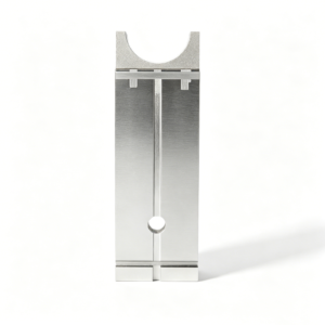


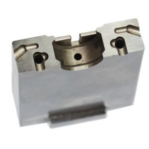


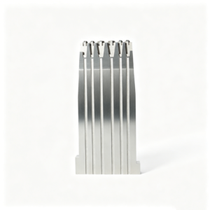
CNC Machined Guide Rails: Engineering Advantages
Plan critical interfaces, process routes, and inspection evidence before production commitments.
Drawing Review First
Review 2D drawings and models for datums, interfaces, machining access, and requirements that should be clarified before quotation.
DFM Risk Screening
Identify tolerance-stack, tool-access, heat-treatment, and finishing risks early so the proposed route aligns with functional guide-rail requirements.
Critical Dimension Planning
Define critical-to-quality dimensions, datum references, and measurement methods to focus manufacturing and inspection effort where performance depends on them.
Coordinated Process Routes
Combine CNC machining, EDM, grinding, and fitting as required by geometry, surface requirements, machining allowance, and verified project needs.
Inspection Plan Alignment
Align inspection methods and reporting expectations with the drawing, priority dimensions, and agreed order requirements before production begins.
Revision Traceability
Combine CNC machining, EDM, grinding, and fitting when geometry, surface requirements, machining allowance, and verified project requirements call for those operations.
Guide Rail and Precision Component Families
Drawing-driven process routes for configurable components, tooling details and custom parts, reviewed against critical dimensions, materials, inspection requirements and delivery needs.

CNC Machining Services
Precision CNC machining services for drawing-based parts requiring planned milling, turning, EDM, grinding and inspection routes. RFQ review considers datums, critical dimensions, material condition, tool access, surface requirements and documentation before production commitments are made.
Upload a Drawing
CNC Milling
Custom CNC milling services for prismatic, contoured and fixture-dependent parts. Machining strategy is evaluated around datum setup, cutter reach, wall stiffness, corner geometry, remaining stock and the dimensions that require inspection after machining.
Upload a Drawing
CNC Turning
Precision CNC turning services for shafts, sleeves, bushings, pins and rotational features. Drawings are reviewed for concentricity, runout, thread requirements, datum references, material condition and secondary operations such as milling, grinding or EDM.
Upload a Drawing
5-Axis Machining
5-axis CNC machining supports parts with angled features, compound contours and difficult tool-access conditions. Process planning assesses setup reduction, cutter orientation, fixturing, feature accessibility and the relationship between critical surfaces and drawing datums.
Upload a Drawing
Swiss & Micro Machining
Swiss machining and micro machining support small, slender and detail-intensive components where part handling and feature sequence affect results. Review focuses on material behavior, minimum features, concentricity, deburring needs, inspection method and production quantity.
Upload a Drawing
Wire & Sinker EDM
Wire EDM and sinker EDM services address hardened materials, narrow slots, internal profiles, sharp internal geometry and features inaccessible to cutting tools. Electrode design, wire path, flushing, recast-layer considerations and finishing allowances are defined from the drawing.
Upload a Drawing
Precision Grinding
Precision surface and profile grinding is applied when flatness, parallelism, profile control or fine surface requirements need a controlled finishing step. Grinding stock, heat-treatment sequence, datum control and inspection criteria should be established before release.
Upload a Drawing
Mold Core & Cavity Inserts
Precision mold core and cavity inserts are produced as configurable tooling components from customer drawings and models. Manufacturing review covers steel selection, heat treatment, cooling or vent features, EDM access, polishing requirements, mating interfaces and critical cavity dimensions.
Upload a Drawing
Ejector & Ejection Components
Ejector pins, sleeves and ejection components are made to drawing-defined dimensions and functional interfaces. Review addresses fit with mating holes, clearance strategy, hardness requirements, head geometry, surface condition, lubrication context and traceable inspection needs.
Upload a Drawing
Core Pins, Guide & Locating Components
Core pins, guide pins and locating components require alignment with their mating parts and assembly datums. SUUXIANG reviews diameters, fits, shoulder locations, wear considerations, hardness sequence, grinding requirements and verification methods for functional dimensions.
Upload a Drawing
Slides, Lifters, Gates & Mold Accessories
Mold slides, lifters, gates and accessories are manufactured as drawing-based assemblies or components within verified scope. Process review examines travel interfaces, angled surfaces, guide relationships, gate geometry, wear areas, assembly allowances and required fitting or inspection evidence.
Upload a Drawing
Connector Mold Components
Precision connector mold components support detail-intensive connector tooling, including inserts, pins, locating features and mating interfaces. Drawings should identify critical pitch, cavity relationships, datum strategy, material and heat-treatment requirements, EDM features and inspection priorities.
Upload a Drawing
Stamping Die Components
Precision stamping die components include drawing-based punches, dies, inserts, guides and related details. Process planning considers material hardness, cutting-edge geometry, clearance relationships, wire-EDM path, grinding stock, surface condition and dimensional verification after heat treatment.
Upload a Drawing
Injection, MIM, CIM & Overmolding Tooling
Injection, MIM, CIM and overmolding tooling components are evaluated where requirements fall within verified production scope. Review considers molding interfaces, material selection, cavity details, venting, gates, inserts, heat-treatment sequence and the dimensions governing fit or product function.
Upload a Drawing
Machining Materials
CNC machining materials are selected against the supplied drawing, application context and required process route. Quote review should define grade or equivalent, material condition, certificates when required, heat-treatment status, corrosion needs and any limits affecting machining or inspection.
Upload a Drawing
Surface Finishes & Heat Treatment
Surface finishing and heat treatment are specified as controlled requirements tied to part function. Clarify coating or finish type, hardness range, treatment sequence, masking needs, post-treatment grinding allowance, surface priorities and the documentation required with the order.
Upload a Drawing
Quality, Metrology & Documentation
Precision inspection, metrology and quality documentation are planned around drawing-defined critical features. Customers should identify reporting expectations, measurement datums, sampling needs, material or treatment records, revision status and any application-specific traceability requirements before production.
Upload a Drawing
Prototyping & Low-Volume Production
Rapid prototyping and low-volume manufacturing support drawing-based validation parts, tooling details and controlled production quantities. Early review identifies design changes, process risks, material availability, inspection scope, revision control and delivery requirements before scheduling work.
Upload a DrawingMaterials Considered for CNC Machined Guide Rails

Alloy Tool Steel
A practical choice for guide components requiring balanced toughness and wear resistance. Commonly considered for rails, locating features, and mating surfaces when machining allowance, hardening sequence, and final grinding requirements are defined in the drawing.

Carbon Tool Steel
Often evaluated for precision guide elements with controlled geometry and heat-treatment needs. Its suitability depends on section size, target hardness, service loading, and whether post-treatment grinding stock is available for critical running surfaces.

Pre-Hardened Steel
Useful where a project may benefit from machining in a supplied hardened condition and limiting downstream heat-treatment distortion. Material condition, machinability, surface requirements, and inspection datums should be confirmed before the process route is released.

Stainless Tool Steel
Considered for guide rail applications where corrosion exposure is relevant alongside precision and wear demands. Grade selection must account for required hardness, machining access, heat-treatment response, surface finish, and the intended operating environment.

Bearing Grade Steel
A candidate for highly loaded or wear-sensitive guide interfaces when the drawing specifies an appropriate hardening and finishing route. SUUXIANG reviews geometry, grinding stock, mating conditions, and inspection requirements before confirming manufacturability.
Precision Processes for CNC Machined Guide Rails

CNC Milling
CNC milling establishes rail profiles, mounting features, slots, and accessible reference surfaces. Tool reach, workholding, stock allowance, and datum sequence are reviewed before machining so critical relationships can be inspected against the drawing.

CNC Turning
For guide components with cylindrical sections, threaded interfaces, or concentric locating features, CNC turning creates stable rotational geometry. The route is evaluated with material condition, runout requirements, downstream grinding, and measurement access in view.


Wire EDM
Wire EDM is considered for narrow slots, precise internal profiles, hardened material, and geometries with limited conventional-tool access. Wire path, start-hole needs, corner conditions, finishing passes, and inspection datums should be defined from the drawing.

Sinker EDM
Sinker EDM addresses formed cavities, sharp internal details, and difficult-access features where electrode geometry governs the result. Electrode strategy, spark allowance, surface expectations, and any required finishing operation are aligned before production.

Precision Grinding
Precision grinding refines functional faces, parallelism, flatness, and controlled stock after preceding operations or heat treatment. Grinding allowance, wheel access, clamping effects, surface requirements, and the final inspection method are planned together.
About SUUXIANG’s Guide Rail Manufacturing Approach

Locating Features
Dowel holes, keyways, shoulders, and reference faces establish repeatable positioning between cnc machined guide rails and mating tooling components. Define datums, fit requirements, and assembly sequence for a practical drawing review.

Ejection Interfaces
Clearance pockets, ejector-pin passages, return-pin seats, and guided contact features can be integrated where the rail relates to mold or tooling motion. Share the moving-component layout, travel limits, and critical interference conditions.

Mounting Patterns
Threaded holes, counterbores, slots, and mounting faces can be configured to suit the intended assembly. Hole position tolerances, fastener specification, access direction, and mating-surface requirements should be identified on the drawing.

Wear Inserts
Replaceable wear strips, hardened contact inserts, and sliding interfaces may be considered for guide and locating functions. Material, heat-treatment sequence, lubrication conditions, and expected contact loads require project-specific review.

Identification Marking
Part numbers, revision marks, cavity identifiers, and orientation references help maintain traceability during fitting, inspection, and service. State marking method, location, legibility requirements, and any restrictions on functional surfaces.

Mating Components
Matching blocks, locating members, stops, and related precision parts can be reviewed alongside the rail to manage assembly relationships. Provide mating drawings or models so datum strategy, clearances, and inspection responsibilities are visible.
About SUUXIANG CNC Machined Guide Rails
SUUXIANG is the public-facing brand of Dongguan SuuXiang Precision Mold Co., Ltd., established in 2010 in Chang’an Town, Dongguan, Guangdong, China. We support international engineering and sourcing teams that need drawing-led production of CNC machined guide rails, precision mold components, connector tooling, die components, and related custom parts.
Our work begins with the drawing, 3D model, material requirement, quantity, application, and quality expectations. Before quotation or production commitments, we review critical dimensions, datums, machining access, heat-treatment sequence, EDM or grinding needs, and inspection requirements so the proposed process route reflects the part’s functional priorities.
SUUXIANG combines CNC milling and turning, multi-axis machining, EDM, precision grinding, fitting, and inspection within a controlled project workflow. What distinguishes our approach is disciplined DFM discussion, visible revision control, and inspection documentation aligned with the verified order and agreed inspection plan.

How to Evaluate a Supplier for CNC Machined Guide Rails
DFM and Datum Review
SUUXIANG reviews drawings, models, mating conditions and critical dimensions before quotation. For CNC machined guide rails, the discussion establishes datum references, straightness priorities, mounting interfaces, tolerance stack risks and the evidence needed to plan a defensible manufacturing route.
- Confirm functional datums and critical-to-quality dimensions
- Review mounting holes, interfaces and machining access
- Identify tolerance-stack and alignment risks early
- Define material, heat treatment and inspection requirements

Machining Route Planning
CNC milling, turning or multi-axis work is selected around the rail geometry, access and required machining sequence. Tool reach, workholding, stock condition and distortion risk are considered so features can be produced from controlled references rather than disconnected setups.
- Plan setups around stable locating surfaces
- Assess tool access for profiles and mounting features
- Sequence roughing and finishing around material condition
- Keep drawing revisions visible through production

EDM and Grinding Strategy
Where geometry, hardness or finish requirements call for it, SUUXIANG evaluates wire EDM, sinker EDM and precision grinding as coordinated operations. The review considers electrode or wire paths, grinding stock, heat-treatment sequence and the surfaces that must remain functionally related.
- Check wire paths for narrow or internal features
- Plan electrode strategy for inaccessible details
- Reserve grinding allowance where required
- Coordinate thermal sequence with final dimensions

Inspection and Revision Control
Inspection planning follows the order’s verified requirements, with measurement methods tied to the agreed datums and critical features. Revision control, documented findings and delivery coordination help procurement and quality teams compare the finished guide rail components against the released drawing.
- Match inspection methods to critical features
- Measure from agreed functional datums
- Maintain traceable drawing revision control
- Align final documentation with the inspection plan

Why Choose SUUXIANG for CNC Machined Guide Rails
A drawing-driven workflow for review, process planning, inspection, and controlled revisions.
← Swipe left or right to view →
CNC Machined Guide Rails: Production and Quality Workflow
A drawing-driven route from RFQ review through controlled manufacturing, inspection, packing, and delivery coordination.
RFQ and Drawing Review
We review drawings, models, material, quantity, delivery, and inspection requirements, identifying critical dimensions, datums, surface priorities, and manufacturability questions before quotation.
Process Route Planning
The team aligns CNC machining, EDM, grinding, heat-treatment sequence, and machining allowances with tool access, tolerance stack, and agreed inspection methods.
Machining and EDM Execution
Production follows the approved revision, combining milling, turning, wire or sinker EDM, and grinding where geometry, hardness, or surface requirements demand it.
Fitting and Dimensional Verification
Parts are fitted as required and measured against agreed critical dimensions, datums, surface requirements, and inspection plans; deviations receive documented review before release.
Packing and Delivery Coordination
Following final inspection, parts are protected for shipment while packing, documentation, revision status, and delivery coordination are confirmed against the order requirements.
Documentation and Evidence Review for CNC Machined Guide Rails
Move from drawing review to documented delivery through a controlled, drawing-driven workflow.
Submit Your Requirements
Send 2D drawings, 3D models when available, material, quantity, critical dimensions, surface priorities, target date, and inspection requirements for your CNC machined guide rails.
Review DFM and Quote
Discuss datum strategy, tool access, heat-treatment sequence, EDM or grinding needs, and inspection methods before SUUXIANG confirms a process route and quotation.
Approve Production Details
Confirm the drawing revision, critical features, process assumptions, quality expectations, and any sample or production-release requirements before manufacturing begins.
Coordinate Documented Delivery
Receive visible coordination on production status, inspection documentation matching the agreed plan, revision traceability, and delivery arrangements for the completed order.
When SUUXIANG Publishes Customer Evidence
Customer Feedback for CNC Machined Guide Rails
Customer testimonials are published only when SUUXIANG has permission to identify the project and verify the stated outcome against the applicable order and inspection records.
For drawing-based guide rail projects, dimensional results, inspection methods, materials, and delivery details are reviewed before any customer feedback is presented as a published case.
Submit an RFQ with your drawing, critical dimensions, material, quantity, and reporting requirements to begin a review tailored to the guide rail application.
The Complete Buyer’s Guide to CNC Machined Guide Rails
Practical RFQ, quality, revision, and delivery questions for drawing-driven guide rail projects.
What information do you need to quote cnc machined guide rails?
Is there a minimum order quantity for cnc machined guide rails?
Can SUUXIANG make samples before production of cnc machined guide rails?
How should I plan lead time for a custom guide rail order?
Can you provide inspection reports with guide rail orders?
How are drawing revisions controlled during production?
How do you handle shipping, payment, and IP-sensitive drawings?
The Complete Buyer’s Guide to cnc machined guide rails
Use this decision framework to specify guide rails, compare materials and manufacturing controls, qualify capable suppliers, and avoid fit, wear, documentation, lead-time, and total-cost mistakes before production.
1. What Are cnc machined guide rails?
SUUXIANG treats cnc machined guide rails as drawing-defined parts: rails, wear strips, gibs, locating bars, or guide faces produced to specified geometry rather than purchased as a catalog motion set. They constrain straight-line travel, establish a repeatable location, carry applied loads through defined contact faces, or provide a replaceable wear surface in molds, dies, fixtures, automation equipment, and connector tooling.
A complete linear-guide assembly normally includes a rail plus a recirculating ball or roller carriage; the machined rail alone is neither that carriage nor a bearing. Machine-integrated box ways are instead guide surfaces cast or machined into a machine bed, an arrangement described at https://jmcncmachine.com/what-is-the-linear-rail-of-cnc-machining-center; they are not typically a separately sourced component.
SUUXIANG needs the drawing to identify the functional faces and datums, rail length and section, mounting-hole pattern, mating component, travel direction, load path, required parallelism or straightness, surface finish, hardness or treatment, lubrication conditions, and inspection method. Those requirements determine whether milling, grinding, EDM, fitting, or a combined route is appropriate.
2. Evolution of cnc machined guide rails
19th-century machine-tool ways relied on broad sliding interfaces, commonly called box ways, with rigidity prioritized over travel speed. That legacy still matters: ‘guide rail,’ ‘guideway,’ and ‘hard rail’ may describe an integral bed feature rather than a separately replaceable component (https://jmcncmachine.com/what-is-the-linear-rail-of-cnc-machining-center).
20th-century hardening, grinding, and improved lubrication made sliding ways more wear-resistant and repeatable, while rail material and hardening method became part of the functional specification. Flame-hardened steels are one established approach for guideways, so a replacement drawing must identify the base material, hardened zone, finish, and any post-heat-treatment grinding requirement (https://www.detroitedge.com/guide-rails).
1960s onward, profiled linear guides using balls or rollers shifted many designs toward lower-friction, separately mounted rail-and-carriage assemblies. For modern cnc machined guide rails, sourcing must distinguish a precision-machined mounting rail from a purchased rolling guide: hole pitch, datum faces, straightness, parallelism, carriage interface, and inspection method determine retrofit compatibility.
3. Types of cnc machined guide rails
Six rail forms are not interchangeable: the motion interface determines load path, alignment sensitivity, and the machining or grinding route required. Specify the rail form before requesting a quotation for cnc machined guide rails.
| Rail Form | Motion Interface | Primary Load | Alignment Detail | Typical Tooling Use |
|---|---|---|---|---|
| Flat or rectangular | Sliding face | Vertical or lateral | Parallelism and flatness | Mold slides |
| V-guide | V and mating groove | Lateral locating | Included angle and apex datum | Locating fixtures |
| Dovetail | Angled sliding faces | Lift and lateral | Angle, clearance, gib | Die and mold slides |
| Round shaft | Bushing or bearing | Radial | Shaft diameter and spacing | Ejector guides |
| Profiled-rail base | Purchased rail mount | Rail-system loads | Hole pitch and datum edge | Automation fixtures |
| Contoured rail | Custom mating profile | Application-defined | 3D path and contact datum | Cam-driven tooling |
Sliding Way Forms
Flat, rectangular, V-guide, and dovetail forms run on mating sliding faces. V forms locate laterally; dovetails resist lift, so their included angle, mating clearance, and lubrication features must be defined.
Round And Profiled Interfaces
Round shafts guide through bushings or bearings and tolerate rotationally symmetric interfaces. Profiled linear-rail bases support purchased rails; identify the rail series, hole pattern, datum edge, and mounting-surface flatness.
Custom Contoured Rails
Custom contoured rails suit slides, cams, or constrained tooling travel. Provide the 3D path, contact profile, stroke limits, load direction, mating-component drawing, and inspection datum so a flat rail is not substituted.
4. Materials for cnc machined guide rails
Three material decisions govern rail performance: load, sliding contact, and environment. Select cnc machined guide rails from the complete heat-treatment and mating-system specification, not the material name alone.
| Family | Key Strength | Key Caution |
|---|---|---|
| Carbon steel | Machinability | Low corrosion resistance |
| Alloy steel | Toughness | Heat-treatment distortion |
| Tool steel | Wear resistance | Difficult machining |
| Stainless steel | Corrosion resistance | Galling evaluation |
| Cast iron | Damping | Mating-surface compatibility |
Compare Material Families
1045-type carbon steel machines economically and can suit lubricated, moderate-duty rails; its corrosion resistance is limited.
4140-type alloy steel adds toughness and hardenability, while tool steel favors wear resistance but raises machining and distortion risk.
Match The Mating Structure
Cast-iron bases provide damping and rigidity, but their rail interface needs compatible hardness, geometry, and lubrication.
Stainless steel is considered where corrosion exposure matters; confirm galling risk against the mating element before specifying sliding contact.
Specify The Process Route
0.01 mm-level geometry can be lost after heat treatment if stress relief, machining allowance, and finishing sequence are omitted.
Hardening depth and final grinding or surface finish should follow contact pressure, lubricant regime, contamination, and required wear life.
5. Custom Options for cnc machined guide rails
One controlled drawing should convert every functional request into dimensions, datums, and acceptance criteria. For cnc machined guide rails, geometry, location features, and finish choices must be reviewed together because they govern fit, inspection, and installation.
| Option | Drawing Control | Assembly Effect |
|---|---|---|
| Hole pattern | Datum-based position | Interchangeability |
| Dowel locations | Size and true position | Location sequence |
| Slots and reliefs | Travel and dimensions | Adjustment clearance |
| Matched sets | Pair ID and orientation | Controlled pairing |
Profile And End Geometry
Two profile decisions—overall section and bearing or reference faces—should be dimensioned from named datums. Specify length, edge breaks, end reliefs, and protected functional surfaces instead of using ‘standard profile’.
Mounting And Location Features
Three locating schemes require distinct callouts: mounting holes, dowels, and adjustment slots. Give hole size, thread, counterbore depth, positional tolerance, datum references, and slot travel; dowels establish repeatable location before screws clamp.
Finish Marking And Sets
One matched-set identifier should link paired rails, orientation, and inspection records. Define coating or lubrication provisions by surface and mask area, then place permanent marking away from bearing contact and assembly clearance.
6. Critical Construction and Quality Elements
Three datums should locate a rail: one mounting face, one side reference, and one end reference. The drawing must connect each functional requirement to those datums, not to unconstrained stock surfaces.
Geometry That Runs Freely
0.02 mm straightness can matter more than a tight local size when a long mating carriage spans the rail; bow promotes binding and uneven contact.
0.01 mm parallelism or flatness requirements should be stated over a defined length and datum. Profile accuracy and hole position control preload, interchangeability, and assembly time.
Surface And Edge Control
Ra values must be specified by functional surface and measurement direction. Rough running faces accelerate wear, while excessive polishing may add cost without improving fit.
0.1–0.3 mm edge breaks are often appropriate when safe handling and burr-free assembly matter. Sharp edges, raised EDM debris, and trapped abrasive can damage mating components.
Hardness And Evidence
After heat treatment, distortion must be evaluated before finish grinding; machining a hardened rail to final geometry without allowance risks rejected alignment.
100% critical-dimension records should accompany the agreed inspection plan. Request a first-article report, material certificate, hardness results, and datum-based dimensional records with revision identification.
7. How to Choose a Manufacturer
Two suppliers can quote the same drawing yet control different risks. For cnc machined guide rails, qualify the review and evidence package before comparing unit price.
| Qualification Area | Ask For | Compare By |
|---|---|---|
| DFM review | Datum and mating-part questions | Actionable risks |
| Process control | CNC, grinding, heat-treatment sequence | Documented route |
| Metrology | Inspection plan and report format | Feature-to-datum coverage |
| Change control | Revision acknowledgement | Traceable communication |
Review Functional Interfaces
First, ask which mating part establishes each functional datum and how parallelism, straightness, mounting faces, and clearance will be inspected.
Second, require a DFM response identifying tool access, grinding stock, heat-treatment distortion risk, and unresolved drawing assumptions.
Verify Process Evidence
Three controls should connect: material traceability, heat-treatment records where specified, and inspection results tied to drawing revisions.
One supplier should explain its CNC, EDM, and grinding route, metrology method, prototype plan, and change-notification process before release.
Compare Quotations Properly
Four quotation fields matter beyond price: included process route, inspection scope, documentation, and revision handling.
Nominal tolerance alone is insufficient; compare datum-based measurements, exclusions, delivery assumptions, and the cost of correcting a mating failure.
8. Common Buyer Mistakes to Avoid
Three review gates—design review, quotation, and first-article approval—should expose rail risks before machining begins. A drawing that defines function, datums, and inspection evidence prevents interpretation from becoming rework.
Datum And Function Gaps
Two missing datum references can make straightness, parallelism, and hole position impossible to relate consistently. The likely result is a rail that meets isolated dimensions but misaligns in assembly.
At design review, identify mounting, travel, and mating datums; at quotation, require the supplier to confirm the measurement setup.
Process Sequence Oversights
Heat treatment can distort a long rail, while an inappropriate finish can alter fit, friction, or corrosion behavior. Treating post-treatment grinding and finishing as secondary invites avoidable stock loss or rejection.
At quotation, state material condition, heat-treatment sequence, grinding allowance, and finish purpose. Before first article, compare the finished part—not only pre-treatment dimensions—to the drawing.
Interface And Acceptance Omissions
Hole patterns, counterbores, and mating-part geometry control installation as directly as the rail profile. Omitting them can create inaccessible fasteners, interference, or a tolerance stack that appears only during assembly.
At design review, provide mating models and fastener details. At first-article approval, define critical features, sampling, datums, report format, and acceptance criteria before approving production.
9. Launching a Custom Rail Program
One controlled launch path prevents a drawing change from becoming an untraceable shop-floor decision. For low-volume cnc machined guide rails, freeze requirements and acceptance evidence before material is released.
Define The Release Package
Two files form the baseline: a revision-controlled 2D drawing and matching 3D CAD model. Include material, heat treatment, datums, critical dimensions, surface requirements, quantity, mating context, and requested inspection records.
One owner should issue every revision through a dated change notice. Withdraw superseded files and identify whether existing material, machining, or inspection evidence remains usable.
Review DFM And First Article
One DFM review should confirm tool access, datum scheme, grinding stock, EDM or wire paths, and measurement method before manufacture. Record open decisions against the drawing revision.
One prototype or first article should be inspected to the agreed critical characteristics. Approval requires documented disposition of deviations, not an informal email release.
Pilot, Pack, And Repeat
One pilot build verifies process repeatability, packaging protection, part identification, and delivery handling. Define spare quantity, rust prevention where applicable, and separation of matched or orientation-sensitive rails.
Each repeat order should reference the approved revision, inspection plan, and prior feedback. Feed assembly findings back into the change record before altering process or acceptance criteria.
10. cnc machined guide rails Pricing and Cost
3 quote tiers make cnc machined guide rails easier to compare: prototypes carry programming, setup, and material-cutting risk; repeat orders can spread those costs across more pieces. Stock cross-section and length, material grade, machining time, grinding passes, heat treatment, coating, and geometric complexity should be itemized rather than converted into a blanket unit price.
1 comparable RFQ package should give every supplier the same revision-controlled drawing, 3D model, quantity breaks, material and hardness, datums, critical dimensions, surface requirements, inspection report format, packaging, and requested delivery date. Ask each supplier to state included operations, assumptions, exclusions, and any tooling or first-article charge separately.
| Order tier | Main cost drivers | Typical quote consideration |
|---|---|---|
| Prototype: 1–5 | Setup, stock size, CNC time, special inspection | Confirm process route and one-off packaging; lead time depends on material and outside processes. |
| Low volume: 6–50 | Grinding, heat treatment, coating, fixture complexity | Compare batch setup allocation, inspection sampling, and delivery split requirements. |
| Repeat order: 51+ | Cycle time, yield, packaging, revision stability | Request price breaks only after the drawing, process sequence, and quality plan are frozen. |
Upload Your CNC Machined Guide Rails Drawing
Submit your 2D drawing, 3D model, material, quantity, critical dimensions, inspection needs, and target delivery date for a disciplined RFQ review.