
Custom CNC Machined Sleeves, Reviewed Before Production
Send your drawing for custom CNC machined sleeves with DFM, critical-dimension review, coordinated machining, and inspection planning.
Representative Components for Custom CNC-Machined Sleeve Development





Related Configurable Component Families and RFQ Support

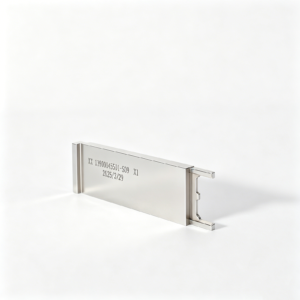


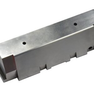


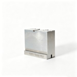
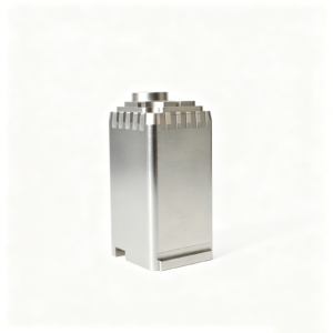

Why Engineering Teams Choose SUUXIANG for Custom CNC Machined Sleeves
A controlled workflow for translating sleeve drawings into inspected parts with visible technical decisions.
Drawing-Led DFM Review
Each RFQ begins with drawings, models, material, quantity, application context, and quality expectations before production commitments are discussed.
Critical Feature Planning
ID, OD, concentricity, threads, grooves, datums, and surface priorities are reviewed to establish a practical machining and inspection route.
Integrated Process Routing
CNC turning, milling, EDM, grinding, fitting, and inspection are coordinated around access, allowance, geometry, and material-condition requirements.
Inspection Matched to Requirements
Inspection planning focuses on the specified critical dimensions, measurement method, reporting needs, and documentation required for the order.
Revision Visibility
Drawing revisions, technical questions, and delivery information remain visible throughout coordination, helping prevent uncontrolled changes during production.
Technical Communication
SUUXIANG discusses manufacturability, tolerance stack, mating conditions, and quality risks directly, so sourcing decisions rest on usable engineering evidence.
Custom Sleeves, Precision Mold Components, and Related Tooling
Drawing-driven process routes for sleeves, mold components, connector tooling, die parts, and related production requirements where fit, wear, location, and alignment matter.

CNC Machining Services
Precision CNC machining services for custom sleeves and related components, planned from drawings around functional fits, critical datums, material requirements, accessible features, and inspection needs before production commitments are made.
Upload a Drawing
CNC Milling
Custom CNC milling services support prismatic sleeve housings, mounting features, locating faces, pockets, and complex mold-component geometry. Tool access, datum relationships, machining allowance, and surface requirements are reviewed to establish a workable route.
Upload a Drawing
CNC Turning
Precision CNC turning services produce cylindrical sleeves, bushings, collars, and rotational features where bore size, concentricity, wall thickness, and mating fit affect assembly performance. Drawings should identify critical diameters, datum references, material, and finish requirements.
Upload a Drawing
5-Axis Machining
5-axis CNC machining supports multi-face components and angled features that benefit from fewer setups. For sleeves and tooling components, process planning considers tool reach, clamping, datum transfer, and whether complex geometry can be machined reliably.
Upload a Drawing
Swiss & Micro Machining
Swiss machining and micro machining support small, slender, or detail-intensive precision components where handling, feature access, and concentricity require careful planning. Provide dimensional priorities, material condition, quantity, and inspection expectations with the RFQ.
Upload a Drawing
Wire & Sinker EDM
Wire EDM and sinker EDM services address narrow slots, sharp internal profiles, hardened features, and geometry unsuitable for conventional cutting. The route should account for wire path or electrode strategy, recast-layer considerations, finish, and downstream fitting or inspection.
Upload a Drawing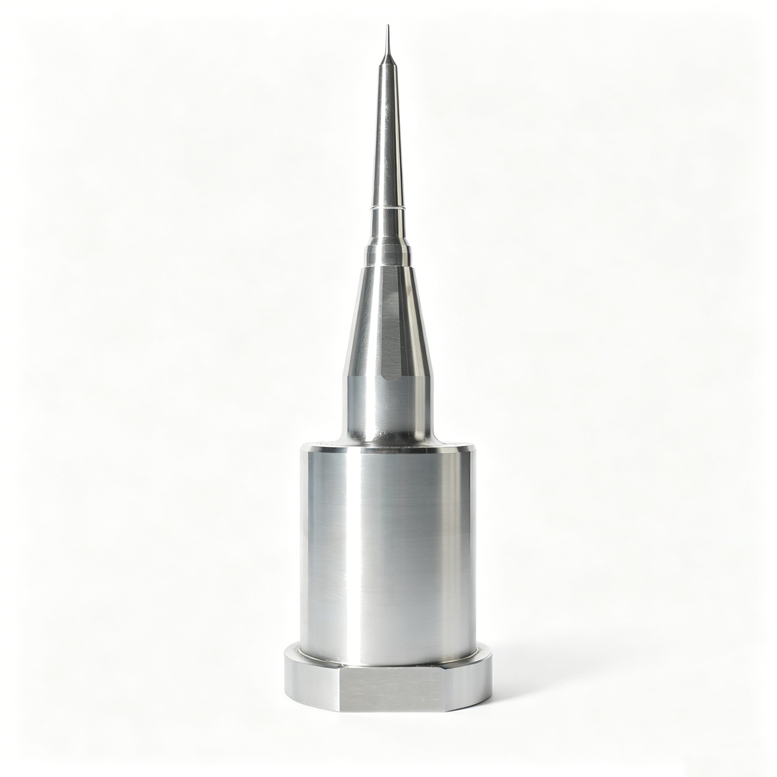
Precision Grinding
Precision surface and profile grinding establishes controlled flatness, parallelism, profile, and final stock removal on critical working surfaces. Grinding stock, heat-treatment sequence, datums, and surface requirements should be defined early to avoid avoidable rework.
Upload a Drawing
Mold Core & Cavity Inserts
Precision mold core inserts and mold cavity inserts are manufactured from customer drawings for molding-tool functions involving shutoff, forming surfaces, alignment, and wear. DFM review addresses material, heat treatment, EDM access, grinding requirements, and critical dimensions.
Upload a Drawing
Ejector & Ejection Components
Ejector pins, sleeves, and ejection components are evaluated around clearance, travel, bearing surfaces, wear, and fit with surrounding mold plates. Specify mating conditions, material and treatment requirements, dimensional priorities, and any inspection reporting needs.
Upload a Drawing
Core Pins, Guide & Locating Components
Core pins, guide pins, bushings, and locating components support repeatable positioning between mold elements and mating assemblies. Drawing review focuses on datum strategy, running or press fits, hardness requirements, concentricity, and wear-critical surfaces.
Upload a Drawing
Slides, Lifters, Gates & Mold Accessories
Mold slides, lifters, gates, and accessories are custom manufacturing families for motion, part release, material flow, and alignment functions. Their process route depends on geometry, bearing interfaces, angle relationships, wear zones, and fitting requirements.
Upload a Drawing
Connector Mold Components
Precision connector mold components support tooling used to form fine connector features and mating interfaces. Buyers should identify critical pin or cavity geometry, pitch-related datums, material and treatment requirements, EDM needs, and inspection priorities.
Upload a Drawing
Stamping Die Components
Precision stamping die components are produced for tooling elements such as punches, dies, guides, and locating parts. Process planning considers material condition, heat-treatment sequence, cutting-edge geometry, grinding stock, alignment, and wear-related tolerances.
Upload a Drawing
Injection, MIM, CIM & Overmolding Tooling
Injection mold components and tooling for MIM, CIM, and overmolding are assessed within verified production scope for forming, locating, gating, and ejection needs. RFQs should include the molding process, material system, part context, critical interfaces, and expected quality evidence.
Upload a Drawing
Machining Materials
CNC machining materials are selected according to drawing requirements, functional loads, corrosion exposure, machinability, heat-treatment sequence, and mating conditions. Material grade, condition, approved substitutions, and certification needs should be stated before quotation.
Upload a Drawing
Surface Finishes & Heat Treatment
Surface finishing and heat treatment are planned as part of the manufacturing sequence, not added after dimensions are finalized. Define required coating, finish, hardness, treatment standard, masking needs, and post-treatment dimensional or grinding requirements.
Upload a Drawing
Quality, Metrology & Documentation
Precision inspection, metrology, and quality documentation are aligned with the order’s critical dimensions and verified inspection plan. Identify CTQ features, measurement methods where specified, report format, traceability needs, and revision-controlled drawing requirements.
Upload a Drawing
Prototyping & Low-Volume Production
Rapid prototyping and low-volume manufacturing support drawing-driven evaluation, tooling development, and controlled production quantities. Quote accuracy improves when the RFQ includes revision status, material, quantity, target date, functional context, and required inspection evidence.
Upload a DrawingMaterials for Custom CNC Machined Sleeves

Stainless Steel
Selected where corrosion resistance, durable threaded features, or repeated handling matter. Grade, hardness condition, and surface requirement should be reviewed with the mating shaft, seal, or housing before turning, milling, grinding, and inspection planning.

Alloy Tool Steel
Considered for wear-intensive sleeve and tooling functions where heat treatment may be part of the process route. Allowance, distortion risk, grinding stock, and critical diameters require definition before machining begins.

Carbon Steel
A practical option for structural sleeves, spacers, and locating functions when the application supports its corrosion behavior. Surface protection, heat-treatment needs, thread form, and fit with mating components should be specified in the RFQ.

Aluminum Alloys
Used when lower mass, corrosion behavior, or efficient machining is relevant to the sleeve design. Wall thickness, clamping strategy, threaded inserts, finish requirements, and contact with harder mating parts should guide the drawing review.

Brass Copper Alloys
Applicable to selected sleeves requiring machinability, conductivity, or controlled contact characteristics. The exact alloy, thread engagement, surface condition, and interaction with the mating assembly should be confirmed before production planning.
Machining Processes for Precision Sleeve Features

CNC Turning
CNC turning establishes sleeve IDs, ODs, lengths, steps, grooves and threads from the drawing datum scheme. Tool access, wall stability and stock condition are reviewed to support repeatable functional fits and controlled surfaces.

CNC Milling
CNC milling adds flats, cross holes, slots, pockets, flange details and other non-rotational features. The machining approach is planned around clamping, feature access and positional relationships to the sleeve’s critical diameters.

Wire EDM
Wire EDM can be considered for precise profiles, narrow slots or hardened features where conventional tool access is limited. Wire path, start-hole strategy and finish requirements are reviewed against the specified geometry and datum references.

Precision Grinding
Precision grinding is applied where the drawing calls for controlled diameters, faces or surface requirements after the relevant machining and material sequence. Grinding stock, heat-treatment effects and inspection method should be agreed before production.

Fitting Inspection
Fitting and inspection verify the features that govern assembly function, including critical IDs, ODs, lengths, threads and mating relationships. The inspection plan follows the approved drawing, revision level and order-specific documentation requirements.
Custom CNC Machined Sleeves: Supporting Features

Internal Threads
Internal threads support retained fasteners, mating components, or adjustment functions. Provide thread standard, class, engagement length, relief requirements, and the datum relationship to critical bores or faces for manufacturability review.

External Threads
External threads can provide mounting, locking, or controlled adjustment on custom CNC machined sleeves. Define the thread callout, runout limits, lead-in geometry, and any surface treatment or post-machining requirements affecting fit.

Functional Grooves
Oil grooves, retaining-ring grooves, and relief features can be machined where assembly or lubrication demands them. Include groove geometry, edge-condition expectations, and its relationship to locating diameters, shoulders, or sealing surfaces.

Locating Shoulders
Shoulders and flange faces establish axial position, bearing contact, or housing references. Identify the controlling datum, face runout or perpendicularity requirements, contact area, and any grinding allowance needed after heat treatment.

Cross Holes
Cross-holes, ports, and radial features may support lubrication, retaining elements, venting, or assembly access. Share hole size, orientation, breakthrough condition, deburring requirements, and the features used to locate the hole.

Surface Requirements
Surface finish, coatings, passivation, or non-marring contact requirements should be tied to the functional surface. State applicable roughness, treatment sequence, masking needs, and inspection method so dimensional priorities remain clear.
Custom CNC Machined Sleeves by SUUXIANG
SUUXIANG is the international-facing precision-manufacturing brand of Dongguan SuuXiang Precision Mold Co., Ltd., established in 2010 in Chang’an Town, Dongguan, Guangdong, China. XiaoCheng Huang is the founder and legal representative. We help global teams convert drawings, models, and specifications into inspected custom CNC-machined sleeves, precision mold components, connector tooling, die components, and other custom machined parts.
Our workflow combines CNC milling and turning, multi-axis machining, EDM, precision grinding, fitting, and inspection. Before quotation or production commitments, we review critical dimensions, datum strategy, material and heat-treatment requirements, machining access, surface priorities, and the inspection evidence required for the order.
What differentiates SUUXIANG is controlled engineering communication. Rather than treating a sleeve as a generic turned part, we plan around functional ID and OD relationships, thread and groove details, concentricity, grinding stock, revision control, and traceable inspection. Upload a drawing with your quantity, quality expectations, and delivery requirements to begin a practical review.

Custom CNC Machined Sleeves: From Drawing Review to Verified Features
DFM and Datum Strategy
Before quotation, SUUXIANG reviews custom CNC machined sleeves against the drawing’s functional datums, mating conditions, critical IDs and ODs, wall thickness, thread callouts, and reachable features. This identifies inspection priorities and process risks before production commitments are made.
- Confirm functional datums and critical dimensions
- Review fits, concentricity, threads, and surface requirements
- Flag tool access and thin-wall clamping considerations

Multi-Process Feature Planning
Sleeve geometry often extends beyond a turned diameter. SUUXIANG plans the appropriate sequence of CNC turning, milling, drilling, grooving, threading, and multi-axis work based on the drawing, material condition, quantity, and feature relationships rather than treating every cylindrical part as a standard operation.
- Match the route to ID, OD, length, and feature geometry
- Coordinate cross holes, flats, slots, and flange details
- Maintain drawing revision visibility through production

EDM and Grinding Allowance
For hardened, fine-featured, or access-limited custom CNC machined sleeves, EDM and precision grinding may be considered within the verified project scope. The planning discussion addresses heat-treatment sequence, electrode or wire path, grinding stock, reference surfaces, and the dimensions that require final-process control.
- Evaluate EDM access before committing the process route
- Define grinding allowance and finishing sequence
- Protect critical references through heat treatment and finishing

Inspection Matched to Function
Inspection planning is tied to the approved drawing and identified critical features, not a generic report template. SUUXIANG aligns measurement methods, acceptance criteria, requested records, part identification, and revision status so the delivered documentation corresponds with the order’s verified quality requirements.
- Identify features requiring documented verification
- Align inspection methods with datums and tolerances
- Include requested reporting and traceability requirements in the RFQ

Custom CNC Machined Sleeves With a Controlled Engineering Workflow
Compare drawing-led planning and inspection alignment with a typical generic machining quote process.
← Swipe left or right to view →
Custom CNC Machined Sleeves: Our Precision Manufacturing Process
Each project follows a drawing-led workflow that aligns DFM, process routing, critical dimensions, inspection requirements, and delivery coordination before release.
Review RFQ Package
We review the drawing, model, material, quantity, application, delivery target, and quality requirements, identifying missing information before quotation or production commitments.
Plan Critical Features
Engineers confirm datums, tolerance stack, ID and OD relationships, wall thickness, surface requirements, tool access, machining allowance, and the appropriate inspection method.
Machine Sleeve Geometry
The approved route combines CNC turning, milling, multi-axis work, or micro machining as needed to establish functional bores, outside diameters, threads, grooves, and features.
Apply EDM or Grinding
Where geometry or finish requirements warrant it, wire EDM, sinker EDM, or precision grinding is planned around access, electrode strategy, grinding stock, and heat-treatment sequence.
Inspect and Document
Parts are checked against the agreed inspection plan, with critical dimensions, surface requirements, and order-specific documentation verified before release and revision status retained.
Pack and Coordinate Delivery
Accepted custom CNC machined sleeves are packed for the component’s handling needs, while shipment timing and final delivery details are coordinated against the confirmed order requirements.
How to Order Custom CNC Machined Sleeves
Move from drawing review to controlled production with clear technical inputs, documented decisions, and inspection planning matched to the order.
Submit Your Requirements
Send the 2D drawing, 3D model when available, material, quantity, target delivery date, critical dimensions, surface requirements, and inspection or reporting expectations.
Review DFM and Quotation
SUUXIANG reviews datum strategy, tolerance stack, tool access, machining route, EDM or grinding needs, heat-treatment sequence, and inspection approach before quotation commitments.
Approve the Production Plan
Confirm the quoted scope, revision level, material requirements, critical features, and any sample, first-article, or inspection-plan requirements needed before production proceeds.
Receive Inspected Parts
Production follows the agreed process route through machining, EDM, grinding, fitting, and inspection, with revision and delivery coordination kept visible throughout the project.
Customer Examples Require Verified Permission and Records
Custom CNC Machined Sleeves: Customer Outcomes Pending Verification
Reserved for a verified customer example documenting the drawing revision, inspection result, and measurable production outcome for custom CNC machined sleeves. Publish only after customer permission, order records, and the applicable inspection documentation have been confirmed.
Reserved for a verified customer example describing a specific DFM or process-planning decision, including the quantified impact on fit, inspection, or delivery. Details will be published only with approved attribution and traceable project evidence.
Reserved for a verified customer example covering controlled production of drawing-based sleeves, with confirmed quantity, revision status, and quality outcome. No rating, customer identity, or performance figure is published before source records and permission are available.
The Complete Buyer’s Guide to Custom CNC-Machined Sleeves
Practical answers for drawing-based sleeve programs, from DFM review through inspection documentation and delivery coordination.
What information should I send for custom CNC machined sleeves?
Is there a minimum order quantity for custom CNC machined sleeves?
How does SUUXIANG review a drawing for custom CNC machined sleeves?
Can you provide samples before production?
Which materials and heat treatments can be considered for sleeve parts?
Can custom CNC machined sleeves include inspection reports?
How are lead time and shipping handled for a sleeve RFQ?
How do you manage drawing revisions and protect project information?
The Complete Buyer’s Guide to custom cnc machined sleeves
Use this decision framework to define fit, material, geometry, inspection, and supplier requirements for drawing-based sleeves—while avoiding tolerance, manufacturability, quoting, and qualification mistakes that create costly assembly risk.
1. What Are custom cnc machined sleeves?
One custom CNC-machined sleeve is a drawing-made cylindrical or profiled part whose bore, outside diameter, faces, grooves, or threads interface with a shaft, bore, bearing, seal, pin, or tooling feature. Its function is defined by the mating assembly, not by its name alone.
Two common roles are controlled spacing and replaceable wear protection; others include locating, guiding, retaining, and creating an internal or external threaded connection. A shoulder, flange, keyway, cross-hole, relief groove, or stepped diameter can turn a simple tube into an axial stop, alignment feature, or serviceable interface.
Five labels are often confused. A bushing usually provides a bearing or wear surface; a spacer establishes axial distance; a collar clamps or stops on a shaft; and a housing supports or encloses another component. Before requesting custom cnc machined sleeves, identify what must mate with the ID and OD, which surface carries load or motion, and whether the part must guide, protect, position, retain, or connect.
2. Evolution of custom cnc machined sleeves
Before CNC, most sleeves were straightforward turned bushings or die components: a bore, outside diameter, face, and perhaps a shoulder. Their acceptance often depended on individual dimensions rather than the assembled relationship between shaft, housing, seal, or tool element.
CNC turning made drawing-controlled repeats practical, while live tooling added cross-holes, flats, drive features, and radial threads without separate setups. Multi-axis machining further reduced datum transfers for parts that combine concentric bores, offset features, flanges, or complex mounting interfaces.
Today, custom cnc machined sleeves are commonly specified as interface components, not generic spacers. Buyers should provide mating dimensions, fit intent, critical datums, material and heat-treatment condition, inspection requirements, and revision status so a supplier can plan setups, control feature relationships, maintain traceability, and reproduce approved low-volume parts across releases.
3. Types of custom cnc machined sleeves
Six configurations cover most drawing-based sleeve requests. Classify the function first, then define the sleeve’s interfaces to shafts, bores, fasteners, seals, or adjacent tooling components.
Straight And Spacer Sleeves

Straight sleeves set axial distance or protect a bore. Specify ID, OD, length, end-face condition, fit class, and mating shaft or housing dimensions.
Stepped And Shoulder Sleeves

Stepped sleeves create a transition or positive stop. Control each diameter, shoulder location, face squareness, corner relief, and the mating counterbore geometry.
Flanged Sleeves

Flanged sleeves provide mounting retention or load bearing. Define flange OD and thickness, bolt pattern if present, face runout needs, and the mating mounting face.
Threaded Sleeves
Threaded sleeves enable adjustment or retention. Call out thread standard, pitch, class, engagement length, thread-to-bore datum, and the mating thread specification.
Grooved And Cross-Drilled Sleeves
Grooves and cross holes support lubrication, retention, or flow. Provide width, depth, position, deburring limits, drill exit location, and mating passage details.
Thin-Wall Precision Sleeves
Thin-wall sleeves require distortion control during clamping and finishing. Identify wall thickness, roundness or concentricity requirements, measurement datum, and installed support conditions.
4. Materials for custom cnc machined sleeves
Six material families cover most custom cnc machined sleeves, but the selection starts with the shaft, seal, lubricant, temperature, and exposure—not the lowest bar price. Confirm the mating materials before fixing the drawing.
| Material | Best Direction | Key Watchpoint |
|---|---|---|
| Aluminum alloy | Low mass, conductivity | Wear; galvanic exposure |
| Carbon/alloy steel | Strength, wear | Corrosion; heat treatment |
| Stainless steel | Corrosive environments | Cost; galling risk |
| Brass or bronze | Conductive or bearing duty | Strength; lubricant compatibility |
| Engineering plastic | Low friction, low mass | Creep; temperature expansion |
Material Trade-Offs
Aluminum is light, conductive, and readily machined, but usually needs protection where sliding wear or salt exposure matters.
Steel provides higher strength and wear potential; stainless favors wet or corrosive service, with slower machining and higher cost direction.
Comparing Common Choices
Brass machines cleanly and conducts heat well; bronze is often considered for bearing duty. Engineering plastics reduce weight, noise, and corrosion concerns, but creep and thermal expansion require fit review.
Interface-Specific Selection
Two mating surfaces determine the real choice: shaft hardness and sleeve contact mode. Abrasive motion may justify a hardened alloy or bronze; seal contact requires compatible finish, lubricant, and corrosion behavior.
Material certification and heat-treatment records matter when chemistry, hardness, traceability, pressure, safety, or regulated end use is specified.
5. Sleeve Features, Finishes, and Marking Options
A sleeve’s functional features should be released from the assembly datum scheme, not selected as decoration. For custom cnc machined sleeves, each added feature changes machining access, inspection planning, setups, and schedule risk.
| Option | Assembly Purpose | Planning Effect |
|---|---|---|
| Threads | Retention or adjustment | Gauge and datum inspection |
| Cross-hole or port | Fluid or pin interface | Extra setup and deburring |
| Flange or shoulder | Axial location | Face runout verification |
| Finish or marking | Protection or identification | Masking and post-process checks |
Functional Geometry
Internal and external threads provide retention or adjustment; specify size, class, engagement length, and thread-to-bore datum. Keyways, flats, grooves, ports, and cross-holes require tool access and explicit burr limits.
Shoulders and flanges establish axial stops or mounting references. Their face position, squareness, and runout should be inspected against the assembly datum.
Finishes By Function
Anodizing, plating, passivation, and black oxide address corrosion, conductivity, wear, or appearance differently. State the required function and any masked threads, bores, or mating faces before a finish route is chosen.
A cosmetic finish needs agreed color, coverage, and acceptable visual limits. An assembly-critical finish also needs a controlled post-finish dimension and inspection method.
Marking And Identification
Laser marking can carry a part number, revision, lot, or orientation mark without adding a separate label. Define location, character height, contrast, depth limits, and whether marking is permitted on functional surfaces.
Revision-controlled identification supports receiving and traceability, while decorative logos rarely improve assembly performance. Confirm marking after finishing when finish coverage or readability matters.
6. Critical Quality Elements for Machined Sleeves
For custom cnc machined sleeves, dimensions must be controlled as mating relationships, not isolated callouts. The drawing should identify critical features, datums, fit intent, and the inspection evidence required for release.
Fit And Coaxiality
ID-to-OD fit class governs insertion force and running clearance; an undersized bore binds, while excess clearance permits looseness and vibration.
Concentricity or total runout tied to a stated datum protects rotating, sealing, and guided assemblies from eccentric wear. Request bore and OD measurements plus a runout record when function is sensitive.
Form, Faces, And Walls
Cylindricity and roundness control how the full bore or OD contacts its mate; local lobing can cause leaks, uneven bearing load, or premature wear.
Face squareness, overall length, and wall thickness establish axial location and thin-wall strength. A first-article report may include CMM results, micrometer readings, and bore-gage data.
Threads And Finished Edges
Thread pitch, major or minor diameter, and thread-to-bore relationship determine whether a sleeve assembles without cross-threading or loss of engagement.
Surface roughness, specified edge breaks, and burr control matter at seals, press fits, and handling interfaces. Use thread gauges, visual burr criteria, roughness records, and photos where the inspection plan requires them.
7. How to Choose a Sleeve Manufacturer
Choose a manufacturer against the sleeve’s drawing, mating interfaces, volume, and evidence requirements. For custom cnc machined sleeves, relevant process control matters more than a generic capability list.
| Evaluation Area | Ask For | Program Value |
|---|---|---|
| DFM | Annotated drawing review | Risks visible early |
| Measurement | Method and capability | Verifiable acceptance |
| Documentation | Material and inspection records | Traceable release |
| Scale-Up | Capacity and packaging plan | Controlled repeat orders |
Review The Drawing Response
One DFM response should address datums, ID/OD relationship, thread access, wall stability, and burr control.
One process plan should identify turning, milling, EDM, grinding, heat-treatment sequence, and material traceability.
Verify Quality Evidence
First-article approval should compare critical dimensions and surface requirements with the released drawing.
In-process and final inspection should state measurement method, sampling, report format, revision, and nonconformance handling.
Test Program Fit
One supplier contact should clarify questions, changes, delivery risks, packaging, and shipment status.
Corrective-action responses should contain containment, cause, corrective action, and effectiveness evidence before repeat production.
8. Common custom cnc machined sleeves Buying Mistakes
Eight recurring release errors turn simple sleeves into fit, quality, or schedule problems. Resolve them during drawing review, when mating data, datum choices, and inspection criteria can still be changed cheaply.
Define Fits With Mating Data
Two nominal diameters do not define an assembly fit. State the shaft and housing limits, intended clearance or interference, datum scheme, and relevant mating-part drawing before release.
Target Tolerances And Materials
One blanket tight tolerance raises machining and inspection effort without improving function. Mark critical features separately, then select material for load, wear, corrosion, temperature, heat treatment, and availability—not unit price alone.
Specify Edges Walls And Threads
0.1 mm burrs can obstruct an assembly or damage seals. Call out finish, edge-break or deburring requirements, minimum wall concerns, clamping-sensitive surfaces, and the complete thread designation including standard, size, pitch, class, and depth.
Approve A First Article
One first article is the practical checkpoint before repeat production. Require measurement results against critical dimensions, verify mating function where feasible, close deviations in writing, and freeze the approved drawing revision.
9. From Drawing Release to Production Launch
A controlled launch begins with the released revision, not a purchase order. For custom cnc machined sleeves, the functional interfaces—shaft, housing, seal, thread, or bearing—must be defined before process planning.
Release the Technical Package
2D drawings should state dimensions, datums, fits, GD&T, material, heat treatment, finish, and revision. A matching 3D model clarifies geometry but does not replace controlled drawing requirements.
- Engineering confirms function and mating interfaces.
- Procurement confirms quantity and target date.
- Quality confirms CTQ dimensions and report needs.
Close DFM And Quotation Gaps
1 DFM review should address tool access, wall stability, workholding, thread strategy, deburring, grinding stock, and inspection access. SUUXIANG should document any assumed datum, material condition, finish masking, or excluded requirement before order release.
- Compare quotation scope with the drawing revision.
- Resolve material and finish callouts.
- Approve any proposed process-route change.
Approve Evidence Before Repeat Production
First-article approval should compare measured results with the locked inspection plan and applicable mating requirements. Any drawing, material, process, or inspection change needs a new revision, written disposition, and traceable communication before production resumes.
- Quality approves sample evidence and acceptance criteria.
- Engineering approves deviations or concessions.
- Procurement releases production only after alignment.
10. custom cnc machined sleeves Pricing and Cost Drivers
1 prototype sleeve concentrates cost in programming, workholding, first-piece verification, and material preparation; these non-recurring steps are divided across few parts. Quote comparison should therefore separate unit price from one-time setup and identify the requested delivery date.
2 repeat orders can reduce unit cost when the released revision, stock size, process route, and inspection plan remain stable. Material form, thin-wall or threaded geometry, tight tolerances, secondary EDM or grinding, finishing, inspection documentation, protective packaging, and expedited scheduling can all change both price and lead time.
| Quantity tier | Cost pattern | Typical lead-time drivers |
|---|---|---|
| Prototype: 1–5 | Highest setup share per sleeve | Programming, stock availability, complex workholding, first article |
| Low volume: 6–50 | Setup spreads across more parts | Machine cycle time, secondary operations, finishing, report scope |
| Repeat order: 51+ | Potentially lower setup share when revision is unchanged | Material release, batch scheduling, packaging, delivery coordination |
Upload Your Custom CNC Machined Sleeves Drawing
Include your 2D drawing, 3D model when available, material, quantity, critical dimensions, inspection needs, and target delivery date for technical review.