
Engineering article
Climb Milling vs Conventional Milling
Climb and conventional milling differ mainly in how the cutter enters the material and directs cutting force. Neither is a universal default. A sound selection considers stock condition, machine backlash behavior, workholding stiffness, feature geometry, surface requirements, and the agreed inspection method before a process plan is released.
On this page
The Direction Changes Chip Formation
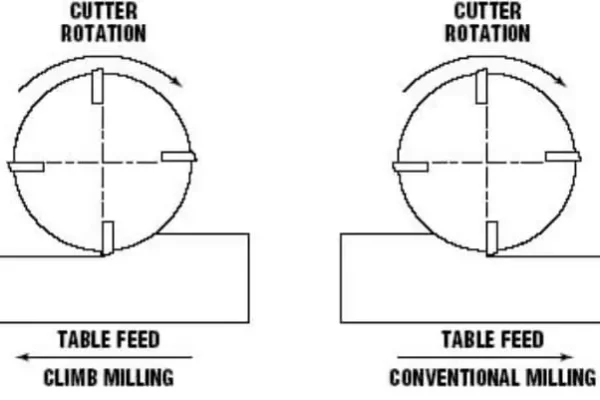
Milling direction describes the relationship between cutter rotation and table feed at the cutting zone. In climb milling, the tooth generally meets the work at its largest chip thickness and exits as the chip thins. In conventional milling, the tooth begins with a thin chip and progresses toward a thicker one before leaving the cut. That changing chip shape affects force, heat distribution, rubbing, and the way a surface is generated.
The comparison should not be reduced to a finish-versus-roughing slogan. A cutter may encounter different engagement conditions around pockets, walls, shoulders, corners, and interrupted surfaces within one program. Radial engagement, axial depth, tool overhang, toolpath transitions, coolant access, and material behavior all influence the practical result. The selected direction belongs in a complete process plan, not as an isolated rule on a drawing.
Force Direction Drives Setup Risk
Climb milling tends to draw the cutter into the workpiece along the feed direction. With a rigid machine, stable toolholder, secure fixture, and controlled engagement, this can support a clean cutting action. Yet that same tendency can magnify motion if a setup has backlash, insufficient clamping, flexible walls, or an unstable part location. The concern is not the label of the method; it is whether the system can resist and repeat the applied forces.
Conventional milling tends to oppose feed motion at the contact zone. That can be useful when the first contact must work through an uncertain outer layer, but it may increase rubbing as the tooth starts its cut. The resulting force path still passes through the cutter, holder, fixture, and part. Thin flanges, long unsupported ribs, and parts held on limited contact pads require a fixture review before direction is chosen.
- Identify which faces establish location and which clamps resist feed-direction load.
- Flag thin sections, unsupported bosses, long tool reach, and low-contact workholding in the request.
- Treat a change in clamping method as a process change that may affect measured geometry.
Surface Condition Alters the Choice
The incoming surface can change the preferred first pass. Oxide, scale, casting skin, welding residue, or inconsistent saw-cut stock may create an irregular and abrasive entry condition. A conventional approach can sometimes be considered for that initial contact because its chip develops from thin to thick. That is a setup-specific response, however, not a blanket instruction for every raw surface or material.
After unstable stock is removed, subsequent passes may use a different direction to suit the feature and finish requirement. Mixed-direction strategies are common in principle: one path addresses stock variability, while another controls a final wall or floor. The drawing should state what matters functionally, such as a sealing face, sliding surface, datum feature, or cosmetic region. It should not prescribe a direction unless that direction is justified by validated design or process requirements.
Geometry Makes One Program Insufficient
External profiles, pocket walls, slot sides, broad floors, and corner blends do not load a cutter in the same way. A continuous outside contour may permit a stable engagement pattern, while a pocket with sharp direction changes can create momentary load increases at corners. Toolpath strategy, corner relief, entry moves, and remaining stock all shape those events. A direction choice that behaves well along a straight wall may need adjustment near an internal radius.
Part geometry also determines what can be reached. Tool diameter, flute length, holder clearance, fixture interference, and required corner radii affect both cutting direction and feasible toolpath. If an internal corner radius is smaller than the practical cutter radius, the solution may require a smaller tool, a different feature definition, or a permitted relief. The engineering agreement should resolve that tradeoff before machining begins rather than relying on an implied machining convention.
- Dimension internal radii and relief features according to functional need, not only visual intent.
- Identify surfaces that need a continuous visual blend versus surfaces where a toolpath witness is acceptable.
- Mark areas where a smaller cutter, secondary setup, or alternate access route is permitted.
Compare the Decision Qualitatively
The table below is a screening aid, not a substitute for trial data or a released process plan. Conditions can reverse the apparent preference. For example, a rigidly supported prismatic part and a flexible near-net-shape component present very different risks even when their nominal material grades match. The applicable drawing, material specification, machine capability assessment, and engineering agreement determine the final method.
| Decision factor | Climb milling tendency | Conventional milling tendency | Question to resolve |
|---|---|---|---|
| Chip development | Starts thicker and thins toward exit | Starts thinner and thickens toward exit | Is the entry surface uniform and clean? |
| Feed-force behavior | Can pull with feed at the cutting zone | Tends to resist feed at the cutting zone | Can the machine, fixture, and part resist the load path? |
| Variable outer skin | May need careful entry planning | May be considered for an initial pass | Are scale, casting skin, or weld remnants present? |
| Flexible geometry | Requires attention to pull-in and movement | Requires attention to rubbing and deflection | Which feature has the lowest stiffness? |
| Final-surface planning | May suit a controlled finishing pass | May suit conditions needing managed initial contact | What surface characteristic and inspection criterion govern acceptance? |
Link Toolpaths to Drawing Control
A machining discussion becomes actionable when the drawing distinguishes critical features from general geometry. Establish datum features, then identify dimensions and geometric controls that locate holes, walls, pockets, and functional faces. Surface texture, edge condition, burr limits, and protected cosmetic areas should be defined where they matter. Vague requests for a “smooth finish” leave too much uncertainty because appearance, roughness, waviness, and toolpath witness marks are not interchangeable requirements.
Inspection planning should follow the same hierarchy. Define whether a dimension is evaluated from a fixture datum, a measured coordinate system, a functional gauge, or another agreed method. For thin or compliant parts, unclamped measurement may differ from the in-process condition. If the part must be measured while supported, restrained, or thermally stabilized, that requirement belongs in the inspection agreement. Milling direction can influence process behavior, but inspection establishes whether the part meets the stated requirement.
- Name primary, secondary, and tertiary datums where feature relationships are critical.
- State the applicable surface-texture notation, edge requirement, and measurement standard.
- Clarify whether cosmetic surfaces permit witness marks, blend areas, or controlled toolpath transitions.
Prepare a Better Quotation Package
Before quotation, provide the current drawing revision, material grade and product form, quantities, and any approved three-dimensional model. Include the starting-stock condition when it is relevant: plate, bar, forging, casting, welded fabrication, or customer-supplied blank. A near-net blank may introduce irregular surfaces and holding issues that are invisible in a finished-part model. State whether material substitution, process alternatives, or minor design-for-manufacture changes require written approval.
Also identify features that drive the process: deep pockets, narrow slots, thin walls, sealing surfaces, threads, precision bores, cosmetic faces, and features requiring a secondary orientation. Give the acceptance criteria for dimensions, geometric tolerances, surface condition, marking, cleanliness, and documentation. If a particular milling direction is required by a validated design reason, communicate that reason and the governing standard. Otherwise, request a proposed process plan that addresses the relevant setup risks.
- Submit native or neutral model data together with the controlled drawing revision.
- Describe blank condition, stock allowance if specified, and any prohibited holding areas.
- List critical features in priority order and identify the required inspection evidence.
- Confirm whether process changes need engineering approval before production.
Questions engineers ask
Is climb milling always better for surface finish?
No. Surface outcome depends on material, tool condition, cutter runout, engagement, rigidity, coolant strategy, toolpath transitions, and the stability of the part and fixture. Define the required surface characteristic and inspection method, then select and validate a process that addresses those conditions.
When is conventional milling worth considering?
It may be considered where the first pass encounters variable, abrasive, or uncertain outer stock, or where the force response of the specific setup favors it. The decision should be based on the actual machine, fixture, material condition, geometry, and engineering requirements rather than a general rule.
Should a drawing specify climb or conventional milling?
Usually the drawing should define the functional geometry, datum scheme, material, surface, edge, and inspection requirements. Specify milling direction only when it is necessary to preserve a validated functional requirement or is controlled by an applicable standard or engineering agreement.
References and further reading
These resources explain related design and manufacturing principles. Project limits, acceptance criteria and process choices must be agreed against the current drawing.
Publication note: this article is general design guidance, not a material specification, a certified inspection report or a guarantee of process capability.
Turn the drawing into a clear manufacturing brief.
Share the current drawing, material, finish and inspection requirements for a project-specific discussion.