
Engineering article
Thread Milling vs Tapping
Thread milling and tapping can both produce functional internal threads, but they create different planning, access, inspection, and recovery conditions. The sound choice begins with the thread callout and part geometry, then considers material behavior, hole type, production volume, machine capability, and verification method. A clear drawing and pre-quote package prevents assumptions from becoming thread-quality risks.
On this page
Start With the Functional Thread
The comparison between thread milling and tapping should start with what the mating assembly needs, not with a default shop preference. Identify the thread designation, governing standard, class or tolerance requirement where applicable, handedness, engagement length, and whether the hole is through or blind. Also establish whether the thread carries clamp load, sees repeated service, seals a fluid path, or merely positions a secondary component. These conditions shape both manufacturing risk and inspection planning.
A thread note alone may not resolve every decision. The drawing should distinguish full usable thread from cosmetic or partial threads near entry and exit. For a blind hole, the required clearance below the functional thread is especially important. The specified material grade, heat-treatment condition, coating sequence, and any customer engineering agreement control the final process decision when they affect thread form or fit.
- State the thread standard and complete designation.
- Show whether the hole is through, blind, interrupted, or cross-drilled.
- Identify the required functional engagement, not only hole depth.
How the Two Methods Differ
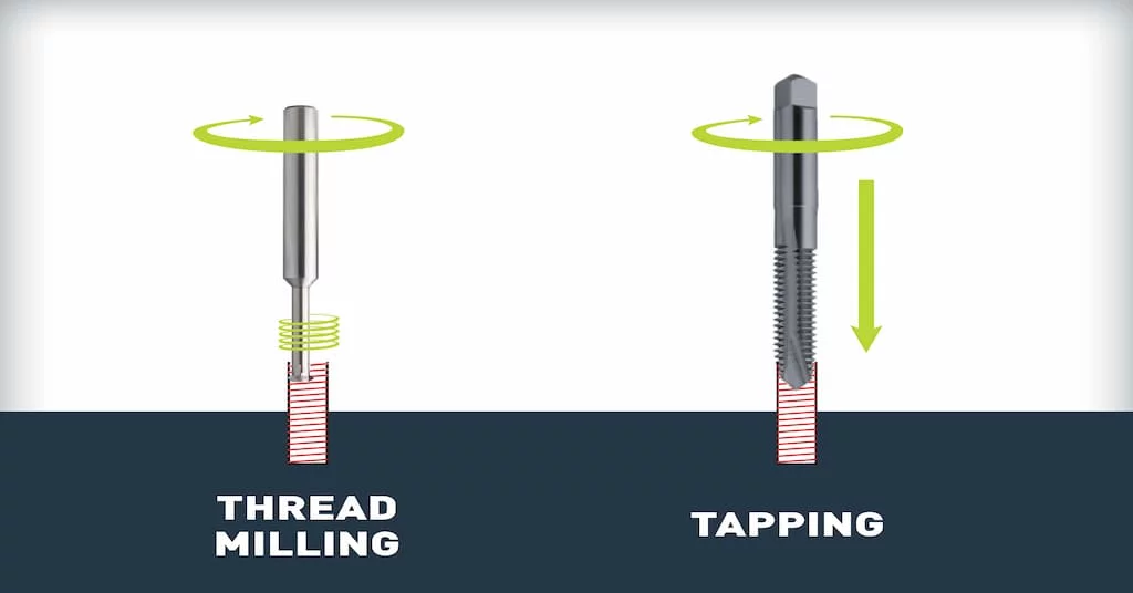
Tapping forms an internal thread by driving a tap through a prepared hole. The tool geometry establishes the thread form in a single axial operation, subject to the selected tap style and process conditions. It is often a direct route for conventional internal-thread features, provided the hole preparation, chip control, alignment, and access are appropriate for the specified thread.
Thread milling uses a rotating cutter following a programmed path to generate the thread. Its path-based nature can offer planning flexibility for certain diameters, materials, or difficult hole configurations. It also changes the failure picture: instead of relying on a full-form tap progressing axially, the process depends on tool path, cutter selection, machine motion, entry strategy, and programmed depth. Neither route is inherently correct without the application context.
| Decision factor | Tapping | Thread milling |
|---|---|---|
| Primary motion concept | A prepared hole is threaded with an axial cutting tool. | A rotating cutter follows a programmed helical path. |
| Planning emphasis | Hole size, tap selection, alignment, lubrication, and chip evacuation. | Cutter geometry, tool path, machine motion, access, and programmed depth. |
| Typical recovery consideration | A damaged tap can create a difficult removal or part-disposition issue. | Tool breakage and thread-form errors still require containment, but failure mechanisms differ. |
| Best selection basis | A validated match to geometry, material, quantity, and quality plan. | A validated match to geometry, material, quantity, and quality plan. |
Geometry Drives Access and Risk
Thread location frequently decides the practical route. Evaluate the available approach direction, surrounding walls, counterbores, shoulders, cavities, and nearby features before assuming either tool can enter and retract safely. Small features, deep recesses, interrupted surfaces, or threads close to a floor can constrain tool length and rigidity. A CAD model may show nominal clearance while overlooking the operating envelope of the selected cutting tool and holder.
Blind holes deserve a separate review. The drill point, chamfer, incomplete thread region, chip space, and required functional engagement all consume axial distance. A nominal hole depth does not automatically establish usable thread depth. Through holes introduce another concern: entry breakout and exit condition may affect assembly, burr control, or downstream finishing. The drawing or process plan should explicitly define any edge-break, chamfer, or burr requirement.
- Check holder clearance as well as cutter or tap clearance.
- Treat cross-holes and interrupted bores as process-review items.
- Define the acceptable condition at thread entry and exit.
Material Behavior Changes the Choice
Material name alone is not enough for thread-process selection. Grade, temper or condition, hardness range, microstructure, and surface condition can change cutting response. Ductile materials may create chip-management concerns; harder or abrasive materials can influence tool wear; work-hardening behavior can narrow the margin for an unsuitable sequence. Material certification may identify the supplied stock, but the drawing and approved process plan determine how its characteristics are handled.
Surface treatment creates another handoff point. If a coating, plating, heat treatment, blasting, or other post-machining operation changes the thread surface or effective fit, the sequence must be agreed before production. Do not rely on a generic allowance. The applicable standard, material system, coating specification, and engineering agreement should state the controlling requirement. This is relevant whether the thread is tapped or milled.
Match Inspection to Drawing Intent
Inspection should verify the requirement that matters in assembly, rather than merely confirming that a tool entered a hole. The governing standard and drawing callout determine the appropriate acceptance approach. Depending on the requirement, verification may include functional gauging, attribute checks, dimensional measurement, visual review of entry condition, or documented first-article evidence. The inspection plan should identify the thread feature clearly, including location, depth reference, and any special acceptance criteria.
Gauge access matters. A thread can be nominally correct in a model yet difficult to inspect if a shoulder, cavity, or adjacent geometry blocks the intended gauge or measurement method. Discuss this early when the feature is critical. Where a functional gauge cannot reach the specified depth, the parties should agree on an alternative verification method before quoting. The method should not be selected after parts are already complete.
- Tie thread acceptance to the stated standard and class.
- Show the datum or face from which thread depth is interpreted.
- Confirm that the proposed inspection method can physically access the feature.
Consider Volume and Failure Containment
Quantity affects the economics of setup, tooling, programming, cycle time, inspection sampling, and process validation. A route suitable for a prototype may not be the preferred route for repeated production, while a production-oriented method may add unnecessary preparation for a small evaluation build. The comparison should use the actual quantity range and anticipated revisions, not an assumed annual volume that may never materialize.
Failure implications deserve equal attention. Tapping-related concerns can include alignment errors, chip packing, thread damage, and tool breakage. Thread-milling-related concerns can include incorrect programming, inadequate tool reach, cutter wear, and profile or depth errors. The practical question is how the selected route detects and contains a deviation at the relevant stage. Critical threads may justify defined verification frequency, traceability, or first-piece approval when required by the quality plan.
Build a Quote-Ready Thread Package
A useful request for quotation gives the manufacturing team enough information to evaluate the thread rather than infer it. Supply a revision-controlled drawing and, when geometry is complex, a matching model. Highlight features that govern route selection: thread callouts, material grade, hole type, engagement requirement, adjacent obstructions, critical interfaces, and finishing sequence. If the thread mates with a purchased component, provide the relevant interface standard or controlled mating information.
Ask for the proposed method to be reviewed against the drawing, but preserve the distinction between a manufacturing suggestion and an approved design change. If a thread form, tolerance, depth, or sequence is altered for manufacturability, record the disposition through the appropriate engineering channel. This keeps the quotation, production plan, and inspection record aligned and reduces the chance that an informal assumption becomes a released requirement.
- Provide drawing revision, model revision, and required quantity range.
- Flag safety-, sealing-, load-, or service-critical threads.
- State required records, inspection evidence, and approval gates if applicable.
- Resolve thread and finish sequencing before release.
Questions engineers ask
Is thread milling always better for difficult materials?
No. Material behavior is one input, alongside thread size, depth, geometry, access, quantity, machine capability, required standard, and inspection plan. The approved process plan should establish the suitable method for the specified material grade and condition.
Can a blind-hole thread be specified by hole depth alone?
No. A blind-hole definition should separately establish usable thread engagement and the clearance needed below it. Tool geometry, hole-bottom form, entry condition, and the governing drawing or standard determine how those requirements are interpreted.
What should be checked when threads follow a surface treatment?
Confirm the specified sequence, affected thread condition, applicable material or coating requirements, and acceptance method. Any allowance or change in thread requirement should come from the controlling specification or engineering agreement, not a universal rule.
References and further reading
These resources explain related design and manufacturing principles. Project limits, acceptance criteria and process choices must be agreed against the current drawing.
Publication note: this article is general design guidance, not a material specification, a certified inspection report or a guarantee of process capability.
Turn the drawing into a clear manufacturing brief.
Share the current drawing, material, finish and inspection requirements for a project-specific discussion.