
Flatness Tolerance for CNC Parts, Molds and Tooling
Define flatness tolerance through practical review of surface function, process routes, inspection needs, and drawing risks before production.
Flatness Tolerance, Reviewed Before Production
SUUXIANG is the sole public-facing brand of Dongguan SuuXiang Precision Mold Co., Ltd., established in 2010 in Chang’an Town, Dongguan, Guangdong, China. Founder and legal representative XiaoCheng Huang leads a company that helps international engineering and sourcing teams turn drawings into inspected CNC-machined parts, precision mold components, connector tooling, and stamping-die components through disciplined project review.
A flatness tolerance is reviewed in context with the surface function, material condition, datum strategy, thickness, machining access, heat-treatment sequence, and inspection requirement. Before quotation or production commitments, our team clarifies critical dimensions and evaluates practical process routes involving CNC machining, EDM, grinding, fitting, and inspection.
What distinguishes SUUXIANG is a controlled, drawing-led workflow rather than a blanket tolerance promise. We keep revision details, inspection expectations, and delivery coordination visible, then align final documentation with the agreed order and verified inspection plan. Upload your drawing with material, quantity, and quality requirements for a project-specific review.

How Flatness Tolerance Shapes Process and Inspection Planning
Define the functional surface, separate form from datum-related controls, and align the manufacturing route with a practical inspection plan before release.
Function Before Value
Set flatness from sealing, mating, locating, or assembly needs, then avoid tighter requirements that add cost without improving function.
Independent Surface Control
A flatness control governs one surface without a datum reference; use datum-related controls when orientation to another feature matters.
Process Route Review
Review material condition, machining access, EDM needs, grinding stock, and heat-treatment sequence before committing to a flatness requirement.
Inspection Method Alignment
Define the inspection method, support strategy, reporting expectation, and critical measurement locations so results match the drawing intent.
Where Flatness Matters in Precision Components
Evaluate flatness alongside datum strategy, mating interfaces, sealing surfaces, stability, process route and inspection requirements before committing a drawing.

CNC Machining Services
Precision CNC machining services support components whose flat mounting faces, mating planes or sealing interfaces require a defined datum scheme, machining access review and an inspection method suited to the drawing.
Upload a Drawing
CNC Milling
Custom CNC milling services are used for plates, inserts and housings where face flatness can affect assembly stability, contact consistency or downstream grinding requirements. Review stock removal, clamping distortion and critical datum relationships early.
Upload a Drawing
CNC Turning
Precision CNC turning services suit rotational parts with faced end surfaces, shoulders and seating features. When flatness affects axial location or a mating interface, define the datum, material condition and inspection approach with the RFQ.
Upload a Drawing
5-Axis Machining
5-axis CNC machining can access compound geometry and multiple faces in fewer setups, helping control relationships between flat pads and complex features. Fixturing, tool reach and any final grinding requirement remain part of the drawing review.
Upload a Drawing
Swiss & Micro Machining
Swiss machining and micro machining support small pins, shafts and connector features where end-face condition or mating geometry may be critical. Discuss material behavior, feature size, deburring and measurement feasibility before production.
Upload a Drawing
Wire & Sinker EDM
Wire EDM and sinker EDM services produce precise profiles, slots and difficult-access features in hardened or pre-hardened workpieces. Flatness requirements should account for EDM strategy, recast-layer considerations, finish allowance and subsequent grinding where needed.
Upload a Drawing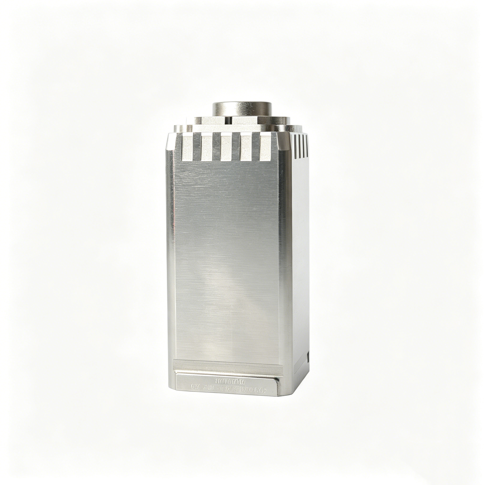
Precision Grinding
Precision surface and profile grinding is applicable when a functional plane requires controlled flatness, parallelism or profile after machining or heat treatment. Specify the functional datum, grinding stock, surface requirement and inspection plan.
Upload a Drawing
Mold Core Inserts & Mold Cavity Inserts
Precision mold core and cavity inserts often rely on flat shutoff, mounting or parting surfaces to support consistent mold assembly and molding performance. Flatness must be considered with heat treatment, EDM, grinding and fitting sequence.
Upload a Drawing
Ejector & Ejection Components
Ejector pins, sleeves and ejection components require reliable movement and seating within the mold assembly. For components with bearing faces or mounting shoulders, define the mating condition, clearance, material treatment and relevant dimensional priorities.
Upload a Drawing
Core Pins, Guide & Locating Components
Core pins, guide pins and locating components establish alignment and repeatable positioning. Flat seating faces, shoulders and locating surfaces should be specified in relation to functional datums, mating bores and the intended assembly method.
Upload a Drawing
Slides, Lifters, Gates & Mold Accessories
Mold slides, lifters, gates and accessories combine moving interfaces with mold-base relationships. Flatness can influence support, wear distribution and sealing or shutoff behavior; evaluate it alongside guide geometry, lubrication and fitting requirements.
Upload a Drawing
Connector Mold Components
Precision connector mold components often contain fine pitch, tightly related cavities and mating features. Flatness of support or insert interfaces can affect alignment and tool stability, so the drawing should identify critical faces and measurement references.
Upload a Drawing
Stamping Die Components
Precision stamping die components use working faces, backing surfaces and guide relationships that must remain stable under forming loads. Flatness requirements should reflect die function, material condition, heat treatment and planned grinding or fitting operations.
Upload a Drawing
Injection Mold Components, MIM, CIM & Overmolding Tooling
Injection, MIM, CIM and overmolding tooling may require stable interfaces between inserts, cavity features and mold-base components. Assess flatness according to sealing, parting, alignment and material-flow functions rather than applying a generic value.
Upload a Drawing
Machining Materials
CNC machining materials respond differently to clamping, stock removal, heat treatment and stress relief. Select a flatness requirement that considers the specified material, component geometry, functional surface and available finishing route.
Upload a Drawing
Surface Finishes & Heat Treatment
Surface finishing and heat treatment can alter surface condition or introduce distortion that affects functional planes. Define sequence, mask areas where applicable, post-treatment stock and whether final grinding or inspection is required for flatness-critical surfaces.
Upload a Drawing
Quality, Metrology & Documentation
Precision inspection, metrology and quality documentation should match the functional requirement. Identify critical flatness callouts, datum references, sampling or reporting needs, measurement method and revision-controlled drawing before production begins.
Upload a Drawing
Rapid Prototyping & Low-Volume Manufacturing
Rapid prototyping and low-volume manufacturing allow teams to validate flat mating faces, sealing concepts and assembly stability before larger tooling commitments. Provide the drawing, material, quantity, target use and inspection priorities for an appropriate process review.
Upload a DrawingFlatness Tolerance: From Drawing Review to Verified Inspection
A disciplined workflow aligns critical surfaces, process choices and inspection evidence before production commitments are made.
Submit Complete Drawing Data
Provide the 2D drawing, 3D model when available, material, quantity, surface requirements, delivery target, and any mating or functional context affecting the part.
Define Critical Surfaces
Review flatness tolerance callouts, datums, critical dimensions, surface finish, heat-treatment sequence, and inspection expectations to identify requirements that influence manufacturability and acceptance.
Plan the Process Route
Select an appropriate CNC, EDM, grinding, fitting, and machining-allowance sequence while checking workholding, tool access, distortion risk, and practical inspection methods.
Confirm Revisions and Evidence
Align the approved drawing revision, quality plan, reporting needs, and delivery details before production, then document inspection results against the agreed critical requirements.
Flatness Tolerance and Related Drawing Controls
Use the right control for surface form, datum relationship, size, and finish before requesting a quotation.
← Swipe left or right to view →
Flatness Tolerance FAQ for Drawing-Based RFQs
Practical guidance for defining, reviewing and verifying flatness requirements before CNC machining, EDM, grinding and inspection planning begin.
What is flatness tolerance on a CNC part drawing?
How do I specify flatness tolerance for a sealing face or mold insert?
Does flatness tolerance require a datum?
How is flatness tolerance measured during inspection?
What information should I provide when requesting a flatness tolerance quote?
Can flatness tolerance be achieved after heat treatment or EDM?
How does flatness tolerance differ from parallelism and surface finish?
Will a tighter flatness tolerance increase cost or lead time?
Submit Your Flatness Tolerance Drawing for Review
Share your drawing, material, quantity, inspection requirements, and delivery target so SUUXIANG can assess process risks before quotation.