
Measure Micro Features for Confident Production Decisions
Learn how micro-feature measurement informs datum strategy, inspection planning, and drawing review before you release precision parts.
What Controls Reliable Micro-Feature Measurement?
Align geometry, datums and inspection methods before releasing machining so critical dimensions can be evaluated against the drawing intent.
Feature Geometry
Define diameter, depth, aspect ratio, edge condition and access before selecting probes, optics, gauges or an EDM and machining route.
Datum Strategy
Establish functional datums and measurement orientation so results reflect mating conditions instead of convenient but inconsistent fixture references.
Tolerance Stack
Review how location, size and form tolerances interact across related micro features before assigning acceptance criteria or inspection sampling.
Method Suitability
Match measuring micro features to geometry, surface condition, required uncertainty and available access; no single method fits every feature.
Fixturing Stability
Plan part support and clamping carefully to prevent distortion, obscured features or inconsistent datum pickup during inspection.
Traceable Reporting
Specify critical dimensions, inspection method, reporting format and revision level so the final record matches the approved drawing requirements.
Where Micro-Feature Measurement Protects Part Performance
Select process routes and inspection methods around the features that govern fit, motion, sealing, electrical alignment, and tool life.

CNC Machining Services
Precision CNC machining services begin with drawing review of critical dimensions, datums, tolerances, and inspection access. For custom components, the machining route and measurement plan should address functional micro features before production commitments are made.
Upload a Drawing
CNC Milling
Custom CNC milling services support prismatic parts, pockets, ribs, and formed surfaces where small features affect assembly or molding performance. Tool reach, corner radii, clamping strategy, and probe access should be reviewed alongside drawing tolerances.
Upload a Drawing
CNC Turning
Precision CNC turning services are suited to shafts, pins, bushings, sleeves, and rotational features. Diameter, concentricity, runout, shoulder location, and surface requirements require an inspection approach tied to the part’s mating function.
Upload a Drawing
5-Axis Machining
5-axis CNC machining helps reach compound angles, contoured surfaces, and features that would otherwise need multiple setups. Measurement planning should account for datum transfer, fixture influence, tool access, and the functional relationship between angled micro features.
Upload a Drawing
Swiss & Micro Machining
Swiss machining and micro machining support slender, small-diameter parts with closely related turned and milled features. Critical diameters, slots, cross holes, and transition areas should be evaluated for measurement repeatability and handling risk.
Upload a Drawing
Wire & Sinker EDM
Wire EDM and sinker EDM services create fine profiles, narrow slots, internal corners, and difficult-to-machine geometry. Electrode strategy, wire path, recast-layer considerations, and inspection of critical edges should align with fit and service requirements.
Upload a Drawing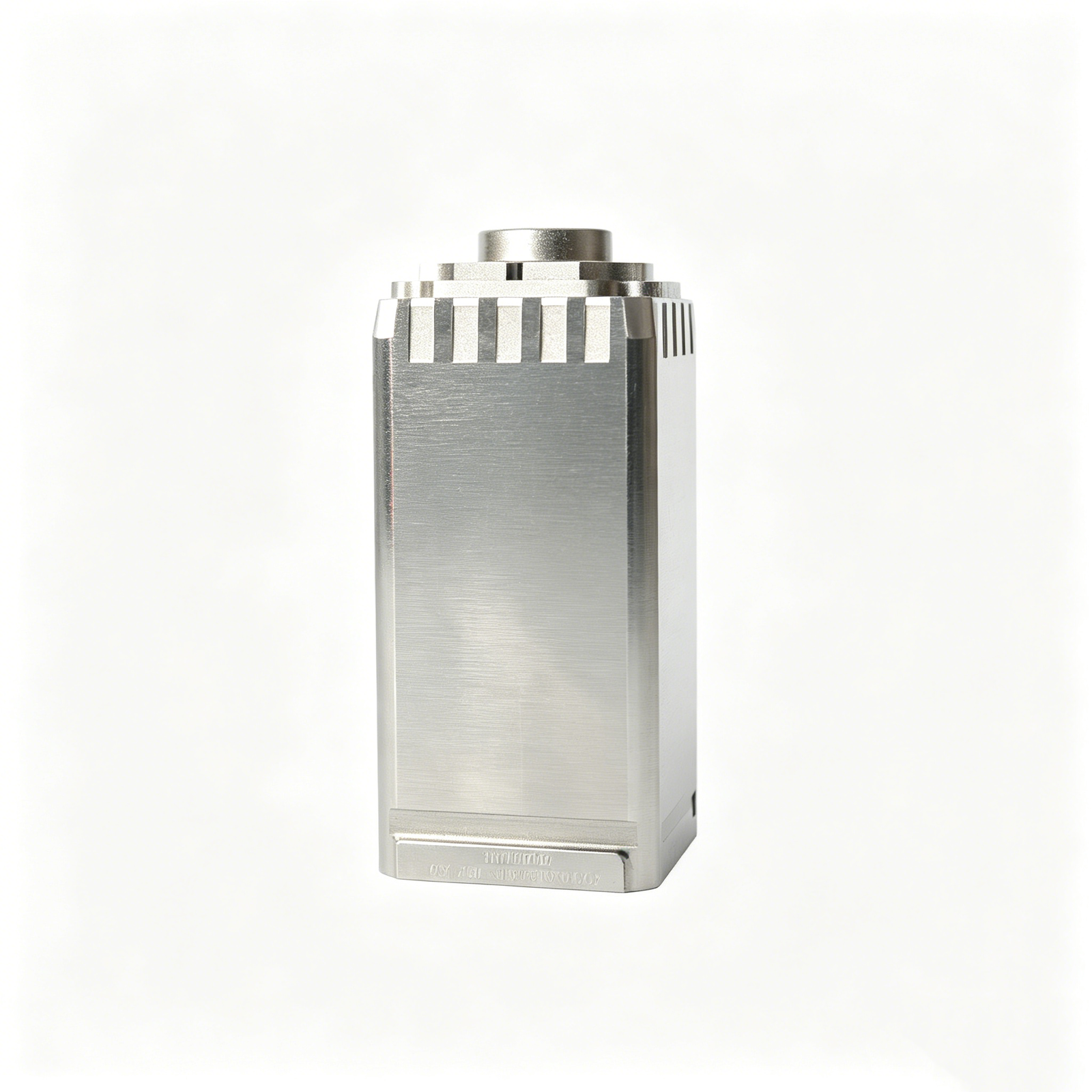
Precision Grinding
Precision surface and profile grinding supports flatness, parallelism, profile accuracy, and controlled finishing stock. Grinding allowance, heat-treatment sequence, datum condition, and the method used to verify micro geometry should be defined before release.
Upload a Drawing
Mold Core & Cavity Inserts
Precision mold core and cavity inserts depend on controlled shutoff geometry, vent details, texture boundaries, and cavity relationships. Inspection should focus on dimensions and profiles that affect molded-part form, flash control, and insert interchangeability.
Upload a Drawing
Ejector & Ejection Components
Ejector pins, sleeves, and ejection components require fit between moving elements as well as dimensional control of working ends. Diameter, clearance, straightness, surface condition, and feature transitions should be reviewed against ejection performance.
Upload a Drawing
Core Pins, Guide & Locating Components
Core pins, guide pins, and locating components establish alignment, repeatability, and feature formation in mold assemblies. Their functional dimensions may include diameters, lengths, coaxial relationships, seating faces, and locating geometry verified against defined datums.
Upload a Drawing
Slides, Lifters, Gates & Mold Accessories
Mold slides, lifters, gates, and accessories combine motion, shutoff, and material-flow functions. Feature measurement should address guiding surfaces, engagement geometry, gate details, and interfaces that influence movement, wear, flash, or molded-part quality.
Upload a Drawing
Connector Mold Components
Precision connector mold components often contain fine cavities, pin features, alignment details, and high-density geometry. Measurement strategy should prioritize the features affecting terminal position, insert alignment, mating relationships, and repeatable tool assembly.
Upload a Drawing
Stamping Die Components
Precision stamping die components require controlled punch, die, guide, and locating geometry to manage clearance and strip progression. Inspection planning should identify the profiles, edge conditions, and relationships that influence cutting performance and tool maintenance.
Upload a Drawing
Injection, MIM, CIM & Overmolding Tooling
Injection, MIM, CIM, and overmolding tooling require component geometry that reflects material flow, shrinkage assumptions, inserts, and mating conditions. DFM and inspection should address fine details that affect part formation, alignment, and tool serviceability.
Upload a Drawing
Machining Materials
CNC machining materials should be selected against load, wear, corrosion, heat treatment, finish, and inspection requirements. Material designation, condition, traceability expectations, and any application-specific restrictions belong in the RFQ before process planning.
Upload a Drawing
Surface Finishes & Heat Treatment
Surface finishing and heat treatment can change dimensions, edges, hardness response, and surface behavior. Specify the required treatment, finish, masking needs, critical dimensions, and inspection timing so machining allowance and final verification can be planned correctly.
Upload a Drawing
Quality, Metrology & Documentation
Precision inspection, metrology, and quality documentation should match the approved drawing and verified inspection plan. Define critical-to-quality features, measurement methods, reporting needs, revision status, material evidence, and any required traceability before production begins.
Upload a Drawing
Prototyping & Low-Volume Production
Rapid prototyping and low-volume manufacturing support drawing-driven evaluation, bridge quantities, and controlled design revisions. Provide models, drawings, material, quantity, functional priorities, inspection requirements, and delivery targets so manufacturability and measurement risks can be reviewed early.
Upload a DrawingPlan Micro-Feature Measurement from the Drawing
Align critical dimensions, process access and inspection evidence before production commitments are made.
Define Critical Dimensions
Provide the drawing, model, material, quantity, datum scheme, surface requirements, and the micro features that affect fit, sealing, electrical function, or assembly.
Review Access and Datums
Confirm feature accessibility, measurement references, tolerance stack considerations, and any requirements that influence machining, EDM, grinding, heat treatment, or inspection sequencing.
Plan the Process Route
Select a drawing-driven route across CNC machining, EDM, grinding, fitting, and intermediate checks, while identifying allowances and revision-controlled technical decisions.
Agree Inspection Evidence
Match the inspection method, reporting format, sampling expectations, and final documentation to the order’s critical dimensions before releasing production.
Compare Micro-Feature Measurement Methods Before Release
Review access, datum strategy, inspection output, and drawing evidence before selecting a production route.
← Swipe left or right to view →
FAQ: Measuring Micro Features on Custom Parts
Practical answers for planning inspection from a drawing, model, and defined critical dimensions.
How should I specify tolerances when measuring micro features?
What datum strategy is needed for measuring micro features?
Which method is suitable for measuring micro features on small CNC parts?
Can you provide an inspection report for critical dimensions?
What information is needed to plan inspection before production?
How do surface finish and heat treatment affect measurement results?
How are drawing revisions controlled during a custom manufacturing project?
Can measuring micro features be planned for connector tooling and mold components?
Review Micro-Feature Measurement Before Release
Upload drawings, models, material requirements, critical dimensions, and inspection needs for a project-specific DFM and measurement review.