
Mold Slides and Lifters: A Practical DFM Guide
Assess mold slides and lifters against undercut geometry, tool access, critical dimensions, and inspection requirements before you submit an RFQ.
How Mold Slides and Lifters Shape Tooling Decisions
Evaluate undercut location, release direction, motion clearance, and production economics before committing the drawing to a tooling route.
Classify the Undercut
Identify whether the feature is external or internal, then define its depth, draft, shutoff geometry, and required release direction.
Set the Motion Path
Confirm slide or lifter travel clears the molded feature, neighboring steel, ejector system, and available mold-base space throughout operation.
Review Tool Access
Assess CNC access, electrode strategy, wire path, grinding stock, and fitting surfaces before releasing complex moving-component geometry.
Protect Critical Interfaces
Specify datums and critical dimensions for shutoffs, guiding, wear interfaces, and mating features so inspection priorities remain unambiguous.
Compare Alternative Routes
Compare automatic actions with hand-loaded inserts using expected volume, repeatability needs, cycle implications, maintenance, and total tooling economics.
Align Evidence Before Release
Provide drawings, models, material and heat-treatment requirements, quantity, inspection expectations, and revision history for a disciplined DFM discussion.
Mold Slides and Lifters: Design Checks Before Specification
Map External Undercuts
For external undercuts, review the shutoff location, slide travel direction, parting-line relationship, and available side clearance before selecting a slide. The drawing should show which formed surfaces move, the datum relationships that matter, and where wear or flash risk may affect the tool design.
- Identify side holes, clips, ribs, and exterior hooks that block straight-pull release.
- Check shutoff geometry, draft, cooling space, and access for machining or EDM.
- Define critical slide-formed dimensions and their inspection datums.

Resolve Internal Undercuts
Internal undercuts often call for a lifter or another ejection strategy, but the choice begins with part geometry rather than a catalog component. Review the required angled release path, local wall thickness, ejection direction, and whether the molded part can remain controlled during release.
- Locate internal hooks, recesses, clips, and features with limited straight-pull clearance.
- Evaluate lifter travel against ejection stroke and the part’s likely retention behavior.
- Confirm forming detail, support, and inspection requirements before production planning.

Prove Motion Clearance
Mold slides and lifters need a documented clearance path through opening and ejection. A practical DFM review compares component geometry, moving interfaces, guide surfaces, and adjacent cavity or core details so interference, dragging, or incomplete release risks are identified before tooling commitments.
- Model the motion sequence in relation to mold opening and ejector travel.
- Check clearance at full retraction, not only at the molding position.
- Flag interfaces that require controlled fitting, grinding stock, or EDM finishing.

Plan the Process Route
Mechanism design and manufacturing route should be reviewed together. Depending on geometry and material condition, precision slide and lifter components may require coordinated CNC machining, wire EDM, sinker EDM, grinding, fitting, and inspection. Final routing should follow the approved drawing and verified project requirements.
- Set machining allowances for surfaces intended for grinding or fitting.
- Review electrode, wire-path, and tool-access needs for narrow or enclosed details.
- Align inspection methods and revision control with critical functional dimensions.

Where Mold Slides and Lifters Resolve Release Risks
Explore the machining, tooling, material, and inspection decisions that affect side-action release, critical interfaces, and drawing-driven production.

CNC Machining Services
Precision CNC machining services support custom components where slide interfaces, lifter bodies, and mating features require a documented route from drawing review through machining and inspection.
Upload a Drawing
CNC Milling Services
Custom CNC milling services machine prismatic slide blocks, lifter bases, pockets, guide features, and mounting faces. Tool access, datum setup, corner conditions, and finish requirements should be reviewed before production.
Upload a Drawing
CNC Turning Services
Precision CNC turning services produce round components such as pins, bushings, sleeves, and locating features used around mold-release mechanisms. Drawings should define functional diameters, concentricity, surface requirements, and mating relationships.
Upload a Drawing
5-Axis Machining
5-axis CNC machining can reach angled faces, compound release geometry, and complex lifter forms with fewer repositioning steps. Feasibility depends on machine access, clamping strategy, tool reach, and inspection datum definition.
Upload a Drawing
Swiss & Micro Machining
Swiss machining and micro machining support small-diameter pins, sleeves, and fine connector-tooling details. Critical features require clear drawing callouts for diameter, straightness, surface condition, and handling expectations.
Upload a Drawing
Wire EDM & Sinker EDM Services
Wire EDM and sinker EDM services address sharp internal forms, narrow slots, hardened features, and geometry inaccessible to conventional cutters. Electrode strategy, wire path, recast-layer expectations, and finishing allowances require review.
Upload a Drawing
Precision Grinding
Precision surface and profile grinding establishes controlled flatness, parallelism, profiles, and sliding fits on wear surfaces. Grinding stock, heat-treatment sequence, datum references, and required measurement methods should be agreed in advance.
Upload a Drawing
Mold Core Inserts & Mold Cavity Inserts
Precision mold core and cavity inserts are machined around the molding geometry and its release requirements. Side-action interfaces, shutoffs, venting, cooling, material condition, and critical dimensions should be assessed from the drawing and model.
Upload a Drawing
Ejector & Ejection Components
Ejector pins, sleeves, and ejection components must work with the molded part and surrounding tooling. Pin location, bearing length, clearance, finish, hardness requirements, and evidence for functional dimensions should be defined before manufacture.
Upload a Drawing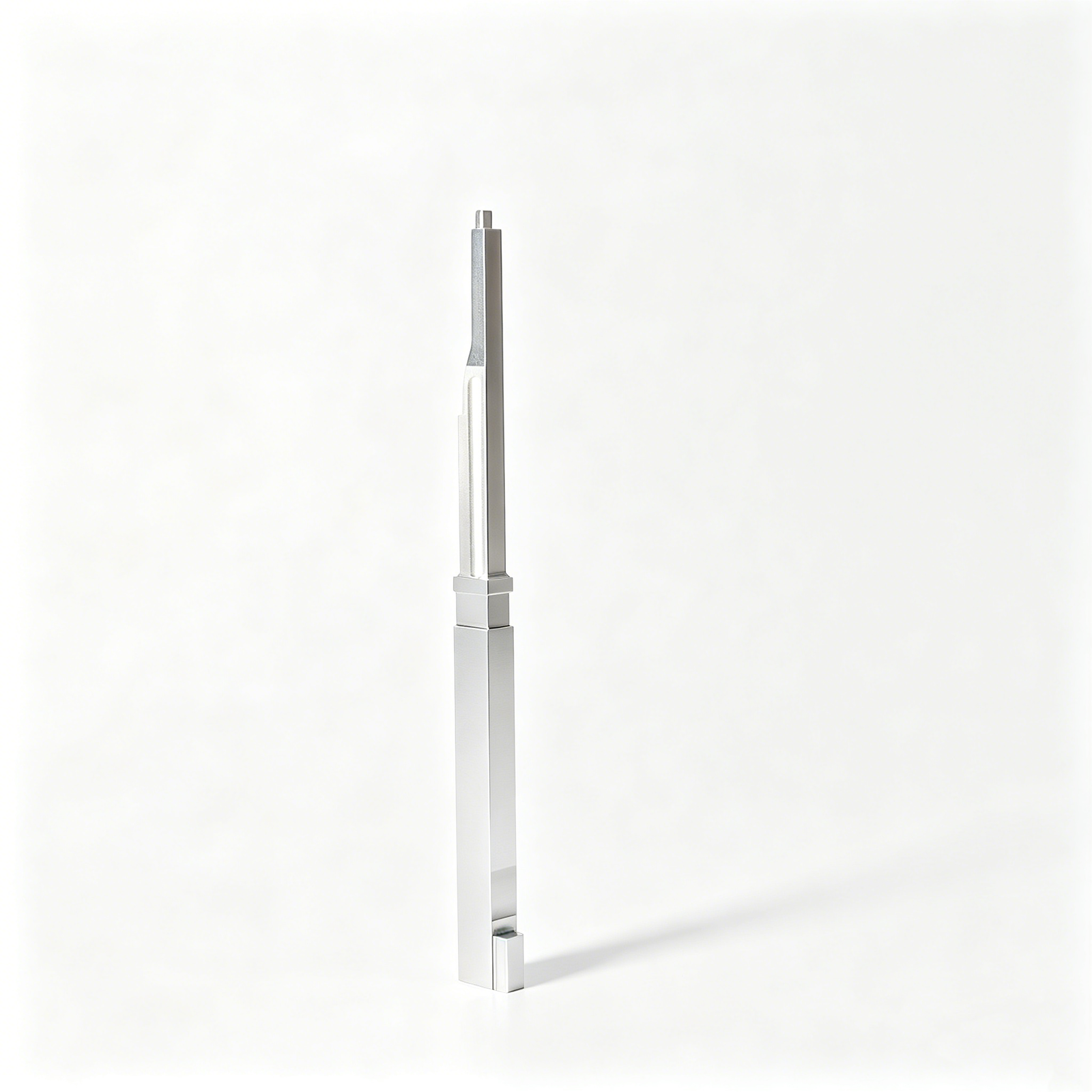
Core Pins, Guide & Locating Components
Core pins, guide pins, and locating components establish alignment and form critical molded features. Their design should consider wear, support length, fit class, datum relationship, replaceability, and inspection of functional mating dimensions.
Upload a Drawing
Slides, Lifters, Gates & Mold Accessories
Mold slides, lifters, gates, and accessories manage undercuts, angled release, material flow, and moving-tool interfaces. A drawing review should confirm travel, interference risk, guide surfaces, shutoff conditions, and assembly relationships.
Upload a Drawing
Connector Mold Components
Precision connector mold components require controlled interfaces for fine-pitch cavities, terminal features, alignment, and repeatable release. Teams should provide mating context, critical dimensions, material requirements, and inspection priorities with the RFQ.
Upload a Drawing
Stamping Die Components
Precision stamping die components include punches, dies, guides, and wear elements whose function depends on clearance, alignment, material condition, and surface quality. Manufacturing route and heat-treatment sequence should follow the approved drawing requirements.
Upload a Drawing
Injection, MIM, CIM & Overmolding Tooling
Injection, MIM, CIM, and overmolding tooling components require process-specific consideration of shrinkage, feed or gate location, release geometry, wear, and mating materials. Capability is assessed against the documented component and production requirements.
Upload a Drawing
Machining Materials
CNC machining materials should be selected for the component’s load, wear, corrosion exposure, heat treatment, and machining route. Specify the required material grade and condition rather than relying on a generic material name.
Upload a Drawing
Surface Finishes & Heat Treatment
Surface finishing and heat treatment can affect size, surface behavior, wear, and fit. Define finish areas, roughness requirements, masking needs, treatment sequence, and post-treatment inspection dimensions before committing the process route.
Upload a Drawing
Quality, Metrology & Documentation
Precision inspection, metrology, and quality documentation should focus on the dimensions that control fit, release, and assembly. Share critical characteristics, datums, reporting format, traceability needs, and revision status with the RFQ.
Upload a Drawing
Prototyping & Low-Volume Production
Rapid prototyping and low-volume manufacturing help validate release mechanisms, assembly interfaces, and revision changes before broader production. Provide current drawings, quantity, material, delivery target, and the dimensions or risks requiring inspection attention.
Upload a DrawingFrom Mold Slides and Lifters Drawings to Inspected Components
Share the drawing package early so DFM, critical dimensions, EDM and grinding requirements, inspection planning, and revision control can be aligned before production.
Submit Complete Drawing Inputs
Provide 2D drawings, 3D models when available, material, heat-treatment, quantity, target date, quality requirements, and mating-component context for a focused technical review.
Review DFM and Datums
Confirm critical dimensions, datum strategy, tolerance stack, tool access, shutoff features, ejection interfaces, and manufacturability risks before quotation or production commitments.
Plan the Process Route
Define the appropriate CNC, EDM, grinding, fitting, and inspection sequence, including machining allowance, electrode strategy, wire path, and heat-treatment timing where required.
Inspect and Control Revisions
Machine against the approved revision, verify dimensions using the agreed inspection method, and keep documentation and delivery information aligned with the confirmed order requirements.
FAQ: Mold Slides and Lifters for Drawing-Based RFQs
Prepare the geometry, critical dimensions, process constraints and inspection expectations needed for a responsible component quotation.
What is the difference between mold slides and lifters?
When should I use mold slides and lifters instead of a hand-loaded insert?
What information do you need to quote mold slides and lifters?
Can SUUXIANG manufacture custom slide and lifter components from drawings?
Which dimensions should be identified as critical on a slide or lifter drawing?
How are mold slide and lifter components inspected?
Do hardened materials change the manufacturing route for mold slides and lifters?
Can you provide DFM feedback before we release the order?
Review Mold Slides and Lifters Before Tooling Release
Upload drawings, material, quantity, critical dimensions, inspection needs, and delivery targets for a project-specific DFM discussion.