
Perpendicularity Tolerance for Drawing Reviews and Inspection
Use perpendicularity tolerance to align datum strategy, machining access, and inspection planning before sourcing precision parts.
How Perpendicularity Tolerance Controls Critical Features
Review the controlled feature, datum reference, and tolerance zone before releasing a drawing for quotation, machining, or inspection planning.
Define the Feature
Identify whether the callout controls a surface, center plane, or axis, then relate that choice to functional mating and assembly behavior.
Select the Datum
Choose a stable functional datum that reflects how the part locates in service, during machining, and when inspected.
Set the Zone Form
Use parallel planes for controlled surfaces or a cylindrical zone for an axis when the drawing requirement calls for it.
Match Functional Risk
Assign the tolerance from fit, sealing, loading, or alignment needs rather than applying a tight value without a functional reason.
Plan Verification Early
Confirm datum setup, fixturing, measurement method, and report requirements before production so the inspection plan matches the released drawing.
Apply Perpendicularity Tolerance to Surfaces and Axes
Control a Surface to a Datum
For a controlled face, perpendicularity tolerance establishes a zone of two parallel planes oriented 90 degrees to the datum. It is not simply an angle note: datum selection, feature-control-frame attachment, machining sequence, and inspection contact strategy must agree.
- Assign the datum to the functional locating surface or feature.
- Attach the feature control frame to the controlled surface.
- Plan milling or grinding access after datum establishment.
- Verify against the defined datum setup, not an assumed 90-degree angle.
- Confirm the GD&T interpretation against the governing drawing standard.

Control an Axis or Center Plane
When perpendicularity tolerance applies to a hole, pin, or other feature of size, the controlled element is typically its axis or derived center plane. The tolerance zone and any material-condition modifier affect both functional interpretation and the inspection method.
- Identify whether the callout controls an axis or center plane.
- Confirm the datum reference frame before selecting a fixture.
- Review feature size, depth, and tool approach together.
- Define probing, gaging, or CMM alignment in the inspection plan.
- Confirm the GD&T interpretation against the governing drawing standard.

Build the Callout Into Process Planning
A perpendicularity requirement should be reviewed before quotation, not treated as a final inspection surprise. SUUXIANG evaluates datum access, clamping distortion, tool reach, EDM or grinding needs, and measurement access so the proposed route can support the drawing’s critical dimensions.
- Share the 2D drawing and 3D model when available.
- Flag mating features and critical-to-quality dimensions.
- State material, heat treatment, quantity, and reporting needs.
- Request DFM feedback before production commitments.

Where Perpendicularity Controls Tooling Performance
Review datum relationships, functional faces, and inspection evidence before committing mold, connector, die, or custom CNC components to production.

CNC Machining Services
Precision CNC machining services should identify the datums that control squareness between mounting faces, bores, and functional profiles. Drawings need critical dimensions, material condition, surface requirements, and an inspection method before the process route is confirmed.
Upload a Drawing
CNC Milling
Custom CNC milling services support prismatic features whose perpendicularity affects assembly, sealing, sliding, or locating performance. Provide datum schemes, feature-access constraints, tolerance-stack context, and any post-machining heat-treatment sequence for drawing review.
Upload a Drawing
CNC Turning
Precision CNC turning services require clear control of the relationship between turned diameters, shoulders, end faces, and secondary features. Specify functional datums, runout or perpendicularity requirements, material, quantity, and whether milling, EDM, or grinding follows turning.
Upload a Drawing
5-Axis Machining
5-axis CNC machining can maintain relationships among angled faces, pockets, bores, and complex profiles when setup strategy matters. Drawings should define datums, inaccessible features, critical perpendicularity zones, surface requirements, and inspection references.
Upload a Drawing
Swiss & Micro Machining
Swiss machining and micro machining demand careful review of tiny shoulders, cross holes, flats, and mating features. State the functional relationship of each feature, applicable datum, material condition, burr limits, inspection approach, and handling requirements.
Upload a Drawing
Wire & Sinker EDM
Wire EDM and sinker EDM services address hard materials, sharp internal geometry, narrow slots, and features where tool access is limited. Confirm wire paths or electrode strategy, datum transfer, recast-layer expectations, finishing allowance, and dimensional inspection requirements.
Upload a Drawing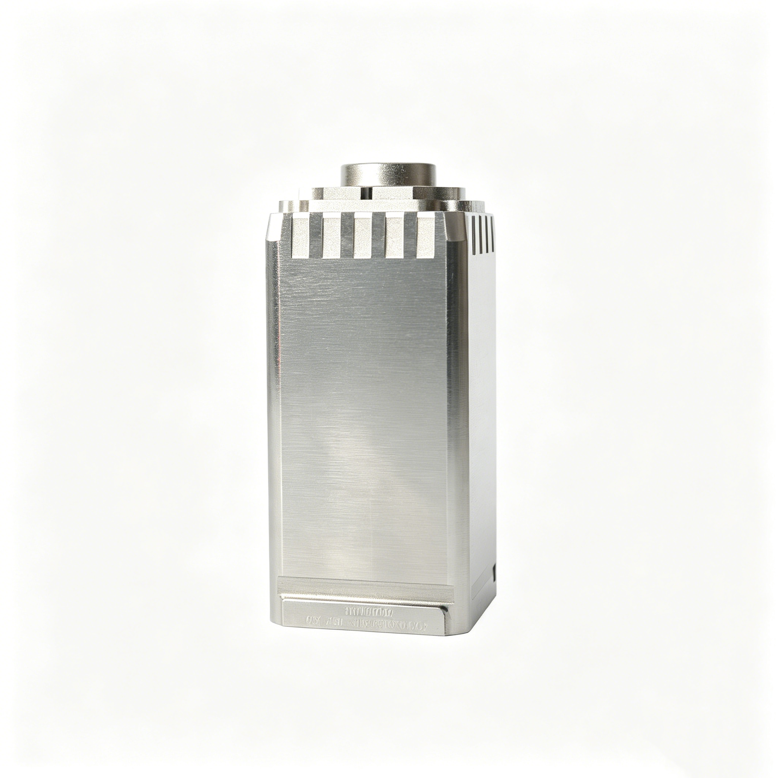
Precision Grinding
Precision surface and profile grinding is often used to establish final flatness, parallelism, profile, and perpendicularity after machining or heat treatment. Define grinding stock, hardened condition, reference faces, critical dimensions, surface finish, and inspection method.
Upload a Drawing
Mold Core & Cavity Inserts
Precision mold core and cavity inserts need controlled relationships between shutoff faces, parting features, cooling interfaces, and locating references. Submit the 2D drawing, 3D model, steel and heat-treatment requirements, critical datums, and inspection priorities.
Upload a Drawing
Ejector & Ejection Components
Ejector pins, sleeves, and ejection components depend on perpendicular contact faces and controlled alignment with bores or guide elements. Identify mating components, clearance requirements, hardened condition, surface finish, critical dimensions, and required inspection evidence.
Upload a Drawing
Core Pins, Guide & Locating Components
Core pins, guide pins, and locating components must preserve positional and perpendicular relationships that determine mold alignment and repeatable seating. Drawings should specify datums, fit classes, mating features, material or heat treatment, surface requirements, and verification criteria.
Upload a Drawing
Slides, Lifters, Gates & Mold Accessories
Mold slides, lifters, gates, and accessories require review of travel direction, bearing faces, shutoffs, mounting references, and assembly clearances. Define functional datums, perpendicularity where motion depends on it, material condition, surface treatment, and mating-part context.
Upload a Drawing
Connector Mold Components
Precision connector mold components often combine fine cavities, core pins, guide features, and tightly controlled datum relationships. Provide connector geometry, mating and parting references, material or hardness requirements, critical dimensions, surface needs, and inspection documentation expectations.
Upload a Drawing
Stamping Die Components
Precision stamping die components rely on square relationships among punches, die openings, guide elements, and mounting faces to control cutting and forming alignment. Include strip or forming context, functional datums, material and heat treatment, clearance requirements, and inspection plan.
Upload a Drawing
Injection, MIM, CIM & Overmolding Tooling
Injection, MIM, CIM, and overmolding tooling requires review of cavity, core, gate, venting, ejection, and alignment interfaces. Define molding process context, shrinkage assumptions, critical datums, steel condition, surface requirements, and component-level inspection needs.
Upload a Drawing
Machining Materials
CNC machining materials should be selected against load, wear, corrosion, thermal behavior, machinability, and downstream heat treatment. Identify the specified grade, material standard, condition, substitution restrictions, traceability expectations, and features that influence the process route.
Upload a Drawing
Surface Finishes & Heat Treatment
Surface finishing and heat treatment can change dimensions, edge condition, hardness distribution, and the final relationship of critical faces. Specify finish or treatment standard, sequence, masking needs, dimensional allowances, post-process grinding requirements, and verification records.
Upload a Drawing
Quality, Metrology & Documentation
Precision inspection, metrology, and quality documentation should be planned from the drawing’s critical dimensions and datum structure. State required reports, measurement methods, sampling expectations, revision level, material records, and any customer-specific traceability requirements before production.
Upload a Drawing
Prototyping & Low-Volume Production
Rapid prototyping and low-volume manufacturing benefit from early review of the features most likely to affect fit, function, or later tooling transfer. Provide current drawings and models, material, quantity, critical dimensions, delivery target, inspection needs, and revision status.
Upload a DrawingFrom Perpendicularity Tolerance Callout to an Inspection Plan
Turn the drawing requirement into a controlled manufacturing and verification discussion before production commitments are made.
Submit Complete Drawing Inputs
Provide the 2D drawing, 3D model when available, material, quantity, mating context, delivery target, and any reporting requirements for the perpendicularity-controlled feature.
Confirm Datums and Critical Features
Review the feature control frame, datum reference, controlled surface or axis, related size tolerances, and critical assembly conditions that determine functional intent.
Plan the Process Route
Evaluate fixturing, machining access, heat-treatment sequence, EDM or grinding needs, stock allowance, and re-clamping risks before selecting the practical manufacturing route.
Define the Inspection Method
Align the inspection approach with the callout, datum setup, feature geometry, measurement equipment, reporting format, and traceability requirements specified for the order.
FAQ: Perpendicularity Tolerance for CNC and Mold Parts
Clarify datum selection, tolerance zones, inspection planning, and RFQ details before committing a precision part to production.
What is perpendicularity tolerance in GD&T?
How does perpendicularity tolerance differ for a surface versus a hole axis?
How do I choose the right datum for perpendicularity tolerance?
Does perpendicularity tolerance also control flatness?
What does a perpendicularity tolerance zone mean on a drawing?
Can perpendicularity tolerance use MMC?
How is perpendicularity tolerance inspected on CNC and mold components?
What should I include in an RFQ with a perpendicularity callout?
Upload Your Drawing for a Perpendicularity Tolerance Review
Include your 2D drawing, 3D model, material, quantity, critical dimensions, and inspection requirements for a scoped manufacturing review.