
CNC Mounts for Optical Alignment, Made From Your Drawing
SUUXIANG reviews critical dimensions, datum strategy, and inspection needs before producing cnc mounts for optical alignment to your verified requirements.
Representative Precision Components from SUUXIANG





Related Configurable Component Families and RFQ Support
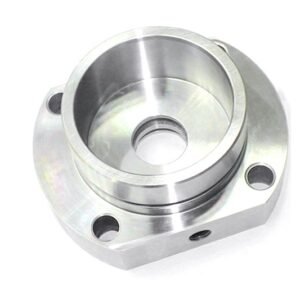


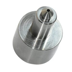


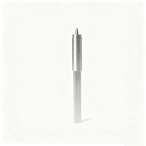

Why Teams Specify SUUXIANG CNC Mounts for Optical Alignment
A drawing-driven workflow for managing functional interfaces, critical relationships, and inspection expectations before production begins.
Drawing-Led DFM Review
We review drawings, models, datums, tool access, and functional interfaces to identify manufacturability questions before quotation and production commitments.
Critical-Dimension Planning
Critical bores, mounting faces, thread locations, and alignment relationships are discussed against the drawing’s datum strategy and inspection requirements.
Coordinated Process Routes
CNC machining, EDM, grinding, fitting, and inspection are planned together when part geometry and surface requirements call for combined processes.
Machining Access Assessment
Tool reach, clamping, wire paths, electrode needs, and grinding allowance are evaluated early to reduce avoidable setup and rework risk.
Inspection Matched to Drawings
Inspection planning focuses on specified critical features, datum references, and reporting needs so delivered documentation matches the verified order requirements.
Visible Revision Control
Drawing revisions, technical decisions, and delivery information remain visible throughout project coordination, helping teams protect configuration control across manufacturing stages.
Related Manufacturing Capabilities for Optical Mount Projects
Drawing-driven process routes for custom alignment hardware, mold components, connector tooling, and low-volume precision parts.

CNC Machining Services
Precision CNC machining services for custom mounts, brackets, housings, and interfaces where datum relationships, mounting patterns, and critical dimensions affect optical alignment or assembly performance. Drawing review clarifies material, access, tolerances, inspection priorities, and the appropriate machining route before production.
Upload a Drawing
CNC Milling Services
Custom CNC milling services support prismatic alignment bases, fixture plates, brackets, and mold components with controlled pockets, slots, bores, and mounting faces. SUUXIANG reviews tool access, datum structure, wall geometry, and machining allowance so dimensions can be inspected against the drawing.
Upload a Drawing
CNC Turning
Precision CNC turning services produce rotational parts such as spacers, bushings, collars, adapters, sleeves, and locating features. Concentricity, runout, threads, shoulders, and mating dimensions should be defined from functional datums, with material and surface requirements reviewed before routing.
Upload a Drawing
5-Axis Machining
5-axis CNC machining helps consolidate complex geometry into fewer setups for optical mounts, shaped inserts, and precision tooling components. The process route is evaluated around tool reach, fixture access, datum transfer, surface orientation, and inspectability rather than assumed from model complexity alone.
Upload a Drawing
Swiss & Micro Machining
Swiss machining and micro machining address small-diameter pins, shafts, sleeves, contact-related features, and miniature locating components. A responsible review considers length-to-diameter ratio, handling, cutoff, deburring, material condition, and measurement method for dimensions that influence fit or alignment.
Upload a Drawing
Wire & Sinker EDM
Wire EDM services and sinker EDM services produce narrow slots, sharp internal profiles, deep features, hardened-tool geometry, and details beyond conventional cutter access. Electrode strategy, wire path, corner conditions, recast considerations, and finishing requirements are reviewed against the functional drawing.
Upload a Drawing
Precision Grinding
Precision surface and profile grinding supports controlled flatness, parallelism, profile accuracy, and finish on alignment faces, hardened inserts, die parts, and gauges. Grinding stock, heat-treatment sequence, datum protection, and inspection method should be agreed before final processing.
Upload a Drawing
Mold Core & Cavity Inserts
Precision mold core and cavity inserts are configured from the molding requirement, material specification, cooling or venting features, surface condition, and critical shutoff geometry. CNC machining, EDM, grinding, fitting, and inspection are planned around the approved drawing and revision.
Upload a Drawing
Ejector & Ejection Components
Ejector pins, sleeves, and ejection components are made to suit the mold’s guided motion, clearance, wear conditions, and molded-part interface. Buyers should identify material, hardness requirements, diameters, lengths, tip geometry, and critical fits for review before manufacture.
Upload a Drawing
Core Pins, Guide & Locating Components
Core pins, guide pins, and locating components establish repeatable mold alignment and controlled feature formation. SUUXIANG reviews mating relationships, datum locations, wear surfaces, heat treatment, grinding requirements, and tolerances that govern interchangeability within the assembly.
Upload a Drawing
Slides, Lifters, Gates & Mold Accessories
Mold slides, lifters, gates, and accessories are drawing-based components whose motion, shutoff, molding interface, and assembly fit must work together. Manufacturing planning considers tool access, EDM needs, hardened surfaces, fitting stock, and inspection points for the specified configuration.
Upload a Drawing
Connector Mold Components
Precision connector mold components support fine-pitch, multi-cavity, and mating-feature tooling where pin geometry, insert alignment, surface condition, and repeatability are consequential. The review should identify critical dimensions, material and heat treatment, EDM or grinding needs, and inspection expectations.
Upload a Drawing
Stamping Die Components
Precision stamping die components include punches, dies, guide elements, plates, and forming details configured for the specified strip, material, and assembly. Process planning addresses working edges, clearance, heat-treatment sequence, grinding stock, mating interfaces, and dimensional verification.
Upload a Drawing
Injection, MIM, CIM & Overmolding Tooling
Injection, MIM, CIM, and overmolding tooling components are evaluated within verified production scope using the drawing, material behavior, parting and gating requirements, mold interface, and quality priorities. CNC, EDM, grinding, fitting, and inspection routes are selected for the required component.
Upload a Drawing
Machining Materials
CNC machining materials are selected from the application, mechanical requirements, corrosion environment, thermal behavior, finish needs, and available specification. Submit the required grade, condition, traceability expectations, and any mating-component context so manufacturability can be assessed accurately.
Upload a Drawing
Surface Finishes & Heat Treatment
Surface finishing and heat treatment are specified where wear resistance, corrosion behavior, conductivity, appearance, or dimensional stability matters. The process sequence must account for machining allowance, distortion risk, masking, post-treatment grinding, and the inspection requirements tied to critical dimensions.
Upload a Drawing
Quality, Metrology & Documentation
Precision inspection, metrology, and quality documentation are planned around the order’s critical dimensions, datums, tolerances, and reporting needs. Buyers should identify required measurement methods, sampling expectations, material records, revision controls, and any inspection report format before production begins.
Upload a Drawing
Prototyping & Low-Volume Production
Rapid prototyping and low-volume manufacturing support design validation, fixture development, pilot builds, replacement tooling components, and controlled production quantities. A complete RFQ includes drawings or models, material, quantity, critical features, inspection needs, target date, and revision status.
Upload a DrawingMaterials for CNC Mounts for Optical Alignment

6061-T6 Aluminum
Lightweight and readily machined for mount bodies, brackets, and optical bench interfaces. Its moderate stiffness and anodizing compatibility suit many controlled environments; review thermal movement, critical datums, and finish buildup against the assembly drawing.

7075-T6 Aluminum
A higher-strength aluminum option for compact mounts, clamps, and loaded adjustment structures. It retains a relatively light feel while providing greater strength than common 6000-series choices; confirm corrosion protection, finish specification, and distortion controls during DFM review.

Stainless Steel
A dense, rigid material for threaded interfaces, wear-prone adjusters, and mounts exposed to demanding environments. Its solid mechanical feel supports durable contact surfaces, while grade selection, machining access, passivation, and magnetic sensitivity should follow the drawing requirements.

Invar Alloy
A low-expansion alloy considered for thermally sensitive reference structures and optical alignment interfaces. Its heavy, stable feel can support temperature-critical assemblies, but material grade, section geometry, machining route, and inspection conditions require project-specific review.

Titanium Alloy
A strong, corrosion-resistant choice for weight-conscious mounts used in demanding industrial or aerospace-adjacent assemblies. It offers a firm, premium mechanical feel and useful strength-to-weight balance; tool access, thread design, surface requirements, and cost implications should be assessed early.

Brass Alloy
A machinable material commonly evaluated for small threaded retainers, spacers, and adjustment-related parts. Its smooth machining behavior can suit fine-featured interfaces, while grade, strength, surface finish, and compatibility with mating materials must be defined in the RFQ.
CNC Mounts for Optical Alignment: Process Routes

CNC Milling & Turning
CNC milling and turning create mount bodies, bores, threads, pockets and interfaces. Setup planning keeps critical features related to their functional datums, reducing tolerance accumulation across the drawing-defined geometry.


Wire EDM
Wire EDM is considered for precise profiles, narrow slots and hardened conductive features where cutter access or cutting forces are limiting. Wire-path planning is reviewed against corner conditions, datum relationships and downstream fitting needs.

Sinker EDM
Sinker EDM addresses internal forms, fine details and cavity geometry that cannot be reached reliably with conventional cutters. Electrode strategy, spark allowance and surface expectations are defined from the drawing and functional requirements.

Precision Grinding
Precision grinding is applied when flatness, parallelism, controlled stock removal or surface condition require a finishing route beyond machining. Grinding allowance and heat-treatment sequence should be confirmed before the process plan is released.

Fitting Inspection
Fitting and inspection verify drawing-defined interfaces, mating relationships and critical dimensions before delivery. The inspection method and required documentation are aligned with the order, revision and agreed quality plan.
CNC Mounts for Optical Alignment: Hardware Features

Threaded Interfaces
Threads for retaining rings, adjustment screws, mounting fasteners, and adapters are planned around engagement, tool access, datum relationships, material condition, and any required post-machining surface treatment.

Locating Features
Dowel bores, precision shoulders, pilot diameters, and reference faces can establish repeatable assembly location when their functional relationship to optical axes and mating components is clearly defined.

Guide Elements
Guide pins, bushings, slots, and alignment keys support controlled fixture or mount positioning. SUUXIANG reviews fit requirements, wear conditions, assembly sequence, and inspection datums against the project drawing.

Surface Treatments
Anodizing, passivation, coating, polishing, or other specified finishes require review of masking, dimensional allowance, contact surfaces, corrosion needs, and functional appearance before the machining route is confirmed.

Part Identification
Laser marking, engraved references, revision identifiers, and traceability markings can be added where permitted by the drawing. Location, depth, readability, finish interaction, and sensitive surfaces should be specified.
About SUUXIANG Precision Manufacturing
SUUXIANG is the international-facing brand of Dongguan SuuXiang Precision Mold Co., Ltd., established in 2010 in Chang’an Town, Dongguan, Guangdong, China. XiaoCheng Huang is the company’s founder and legal representative. We help global engineering, sourcing, and quality teams translate drawings and specifications into inspected custom parts, precision mold components, connector tooling, and CNC mounts for optical alignment.
Our work is planned around the features that affect function: datums, critical dimensions, tolerance relationships, material and heat-treatment requirements, tool access, EDM strategy, grinding stock, and inspection methods. CNC milling and turning, multi-axis machining, EDM, precision grinding, fitting, and inspection are coordinated according to the verified needs of each project.
What distinguishes SUUXIANG is a disciplined drawing-to-inspection workflow rather than a generic quotation process. Before production commitments, we review manufacturability, revision status, quality expectations, and delivery requirements with the customer. This creates clearer production routes, more useful communication, and documentation aligned with the agreed inspection plan.

CNC Mounts for Optical Alignment: Core Manufacturing Controls
Drawing and Datum Review
Before quotation, SUUXIANG reviews the drawing, model, mating context, datum scheme, critical bores, mounting faces, threads, and adjustment interfaces. This clarifies which geometric relationships govern alignment and identifies dimensions that need a defined inspection method before production planning begins.
- Confirm functional datums and critical-to-quality features
- Review bore, face, thread, and hole-pattern relationships
- Identify tool access, clamping risks, and tolerance-stack concerns
- Align drawing revision and inspection expectations

Process Route Planning
CNC mounts for optical alignment often require more than a single machining setup. SUUXIANG plans an appropriate route across milling, turning, multi-axis machining, EDM, grinding, fitting, and finishing while considering feature access, workholding, machining allowance, and the required final condition.
- Sequence machining around functional reference surfaces
- Assess when EDM or grinding supports the geometry
- Plan allowances for heat treatment or specified finishing
- Reduce unnecessary re-location of critical features

Critical Feature Control
Alignment performance depends on controlled relationships, not an isolated general tolerance. SUUXIANG focuses process discussion on the dimensions that affect assembly: bore-to-face orientation, mounting-pattern position, thread engagement, flatness, runout, and interfaces with lenses, sensors, stages, or adjacent tooling.
- Prioritize dimensions tied to the optical assembly
- Relate measurement to the drawing datum structure
- Separate functional requirements from noncritical geometry
- Clarify surface and post-treatment conditions

Inspection and Revision Coordination
For drawing-based CNC mounts for optical alignment, inspection planning and revision control must remain connected to the order. SUUXIANG coordinates agreed measurement requirements, records the applicable drawing revision, and prepares final documentation to match the verified inspection plan and project requirements.
- Define requested reports before production release
- Track drawing revisions and approved changes
- Use suitable inspection methods for specified features
- Coordinate documentation with delivery requirements

CNC Mounts for Optical Alignment: Procurement Comparison
Compare the drawing-review and documentation expectations that should be clarified before production.
← Swipe left or right to view →
CNC Mounts for Optical Alignment: From Drawing Review to Delivery
Each route follows the verified order requirements, critical dimensions, process needs, inspection plan, and delivery priorities.
Review RFQ Inputs
We review drawings, models, material, quantity, application context, quality requirements, and target delivery date before defining the quotation basis.
Align DFM Requirements
Critical dimensions, datums, tolerance stack, tool access, surface requirements, machining allowances, and revision status are clarified with the customer.
Plan Process Route
The team selects the appropriate CNC, EDM, grinding, fitting, and heat-treatment sequence according to verified geometry, material, and functional requirements.
Machine Critical Features
Production follows the released drawing and process plan, with attention to locating interfaces, bores, threads, mounting faces, and burr control.
Inspect and Document
Completed parts are checked against the agreed inspection plan, with dimensional records and documentation matched to the verified order requirements.
Pack and Coordinate Delivery
Parts are protected for shipment and delivery information is coordinated with the customer, keeping revision, quantity, and documentation requirements visible.
How to Source CNC Mounts for Optical Alignment
Give SUUXIANG the technical context needed to review manufacturability, plan inspection, and coordinate production against your approved drawing revision.
Submit Drawings and Models
Upload the 2D drawing and available 3D model, identifying the applicable revision, functional interfaces, datums, critical dimensions, and surface requirements.
Define Project Requirements
State material, heat treatment, quantity, application context, delivery target, inspection reports, and any mating-part details that influence CNC mounts for optical alignment.
Review DFM and Quotation
Assess SUUXIANG’s manufacturability feedback, proposed process route, machining access, EDM or grinding needs, inspection approach, and quotation assumptions before commitment.
Approve Samples or Production
Confirm the agreed revision, quality expectations, and delivery details. SUUXIANG then coordinates approved machining, inspection, documentation, and project communication through shipment.
Quality Documentation for CNC Mounts for Optical Alignment
CNC Mounts for Optical Alignment: Customer Project Feedback
Approved customer testimonial pending. Publish only after the customer confirms the application, measurable outcome, wording, company attribution, and permission to use its name in connection with CNC mounts for optical alignment.
Approved customer case pending. Document the drawing revision, critical dimensions, inspection evidence, quantity, and verified production result before presenting this project outcome as a SUUXIANG customer testimonial.
Approved customer testimonial pending. Confirm the optical-alignment application, process route, reported result, attribution details, and publication permission before replacing this placeholder with a verified customer statement.
CNC Mounts for Optical Alignment FAQ
Practical answers for teams sourcing drawing-based optical mounting components, with scope and commitments confirmed during technical review.
What files should I send for CNC mounts for optical alignment?
Can SUUXIANG manufacture cnc mounts for optical alignment from a custom drawing?
What tolerance information is most important for cnc mounts for optical alignment?
Is there a minimum order quantity for custom optical mount components?
Can I request a sample before placing a larger production order?
How are material, anodizing, plating, or other surface requirements handled?
What inspection reports can be provided with CNC optical mount orders?
How are lead time, shipping, payment, and IP protection addressed?
The Complete Buyer’s Guide to CNC Mounts for Optical Alignment
Use this decision framework to specify alignment-critical CNC mounts, compare material and inspection requirements, evaluate drawing-based suppliers, and avoid tolerance, finish, cleanliness, and sourcing mistakes that can compromise optical assembly performance.
1. What Are cnc mounts for optical alignment?
SUUXIANG defines cnc mounts for optical alignment as drawing-based optomechanical parts that establish a controlled mechanical reference for an optical assembly. They are not lenses, mirrors, prisms, or detectors; they locate, retain, position, or connect those optical elements to the surrounding structure.
2 functional references commonly govern a mount: the optical-axis datum and the assembly datum. Bore centerlines, seating shoulders, mounting faces, and hole patterns influence axis location, tilt, axial spacing, and whether an assembly returns to the intended position after removal and reinstallation.
2010-established SUUXIANG scopes this work as custom manufacturing rather than a catalog of standard optics hardware. Typical parts include bases, brackets, lens seats, fixtures, carriers, spacers, and related low-volume precision components, produced to the drawing’s material, datum, surface, inspection, and revision requirements.
2. Evolution of Optical Alignment Mounts
Three-point kinematic support established a practical way to constrain an optic while preserving adjustment freedom; earlier bench setups often relied on fixed brackets, manual shimming, and operator judgment. Those arrangements could work in one-off laboratories, but they made relocation, replacement, and repeatable assembly difficult.
By the late 20th century, standardized posts, rails, threaded interfaces, and adjuster-driven mounts made optical layouts more modular. Repeatability became a purchasing requirement because an exchanged mount had to return an optic to a known mechanical reference, not merely fit its fasteners.
Today, miniaturized instruments, automated assembly, and tighter alignment budgets expose errors that generic machining assumptions can hide. A mount can meet separate size tolerances yet shift an optical axis through datum mismatch, bore-to-face error, thread runout, or uncontrolled mating-face geometry; buyers should therefore specify functional datums, assembly interfaces, and inspection evidence in the drawing review.
3. Types of cnc mounts for optical alignment
Six mount families cover most drawing-based optical interfaces. Selection starts with the required datum, permitted adjustment, and the repeatability needed after removal or service.
Fixed Bases And Brackets
Two fixed families establish a stable reference: bases locate to a bench, while brackets position an optic or subassembly. Specify mounting-hole position, dowel bores, datum faces, access clearances, and ask whether adjustment occurs elsewhere.
Zero intentional adjustment favors repeatable reinstallation when dowels or defined contact faces carry location. Confirm load direction, fastening sequence, and whether bolt clearance must accommodate assembly variation.
Adjustable And Retaining Mounts
Two adjustable families serve different axes: kinematic mounts use pivots and adjusters for tip/tilt, while lens seats use bores, shoulders, and retaining threads. Define adjustment travel, locking method, optical-axis datum, bore-to-face geometry, and retaining-ring tool access.
Three-point adjustment enables alignment but can reduce repositioning repeatability versus a fixed seat. Ask whether the optic is adjusted once, repeatedly serviced, or exposed to vibration.
Locating Carriers And Blocks
Three locating forms handle interfaces: V-grooves or prisms constrain round parts, dovetail carriers provide guided translation, and custom blocks join unlike assemblies. Draw groove angle, contact lines, dovetail flank datums, stop faces, clamp access, and mating-part tolerances.
Defined contact geometry improves repeatability but limits adjustment unless slots or shims are designed in. Ask which component supplies the datum, whether interchangeability is required, and how contamination will be controlled.
4. Materials and Finishes for Optical Mounts
Five material families cover most optical-mount decisions; selection follows thermal drift, load path, environment, and magnetic constraints. SUUXIANG should review these requirements against the drawing before committing a process route.
| Material | Design Strength | Thermal Or Magnetic Consideration | Finish Direction |
|---|---|---|---|
| Aluminum alloy | High stiffness-to-weight; easy machining | Higher expansion than steel | Black anodize; mask fits |
| Stainless steel | Strong and corrosion resistant | Confirm grade for magnetism | Passivation if specified |
| Low-expansion alloy | Stable for thermal-critical interfaces | Low expansion; verify material | Application-compatible finish |
| Titanium | Light and corrosion resistant | Moderate expansion; difficult machining | Specified protective finish |
| Engineering polymer | Lightweight insulating features | Creep and high expansion | Use only where functional |
Match Material To System
6061 aluminum is a practical lightweight, machinable choice for many mounts; stainless improves corrosion resistance and may be specified nonmagnetic by grade. Invar-type low-expansion alloys suit thermal-critical interfaces, while titanium trades machining ease for corrosion resistance.
Engineering polymers are appropriate only for noncritical, low-load insulating or lightweight features; creep, moisture response, and thermal expansion must be assessed. The system’s operating temperature and environmental exposure govern the final choice.
Control Black Anodizing
Black anodizing on aluminum can reduce stray-light reflections, while substrate texture differences can produce visible color variation.
Masked threads, bores, datum pads, and contact faces must be identified on the drawing. Coating buildup changes functional dimensions, so allowance, finish class, and post-finish inspection method require agreement before release.
Specify The Finish Package
304 or 316 stainless may need passivation or another specified treatment for its service environment; titanium and low-expansion alloys need finish choices compatible with the application. Magnetic sensitivity is a system requirement, not an assumed property of every stainless grade.
0.001 mm of unmanaged coating thickness can matter on close fits. State the finish, masked zones, appearance expectation, and whether dimensions apply before or after finishing.
5. Custom Features and Interface Options
A drawing-driven interface begins with the assembly’s locating logic, not a list of features. For cnc mounts for optical alignment, define what locates, what clamps, and what adjusts before tolerancing individual holes.
Locate Before Clamping
Two dowel holes and a mounting-hole pattern need separate functional roles: dowels establish repeatable position, while screws provide clamp load. Dimension both from named datums and state the mating dowel, fastener, and assembly sequence.
One bore, shoulder, or seating face can control optical-axis location only when its relationship to the mounting datum is specified. Add position, perpendicularity, runout, or flatness only where the alignment budget requires it.
Specify Access And Adjustment
Three common interfaces—threads, pockets, and cable clearances—require depth, tool-access, and edge-condition callouts. Blind threads need usable thread depth; recessed pockets need corner-radius allowances; cable routes need the mating connector envelope.
Two adjustment screws or a slotted pattern should state travel, neutral position, locking method, and allowable backlash. Extra orientations, angled features, and cross-hole intersections can add setups and inspection effort.
Separate Finish From Function
One engraved part number or revision mark supports assembly traceability when its location, character size, and restricted areas are defined. Keep engraving away from datum faces, sealing lands, and particle-sensitive optical cavities.
Surface-treatment callouts should identify the process, color or appearance where relevant, masked interfaces, and post-treatment dimensional requirements. Cosmetic uniformity is different from a functional low-reflectance, corrosion, wear, or electrical-contact requirement.
6. Quality in cnc mounts for optical alignment
Functional datums—not nominal outside faces—should locate every optical axis and mounting interface. Allocate flatness, perpendicularity, position, and runout from the system’s permitted decenter and tilt budget before selecting tolerances.
| Feature | Functional Risk | Useful Evidence |
|---|---|---|
| Mounting face | Tilt | Flatness result |
| Pilot bore | Decenter | Position and runout |
| Threads and edges | Particle release | Gauge and visual record |
Datum And Geometric Controls
Primary, secondary, and tertiary datums should reflect the assembled seating faces, pilot bore, and fastener interface. Control bore-to-face perpendicularity, mounting-face flatness, hole true position, and bore runout to those functional references.
Surface And Thread Condition
Thread gauges confirm form and engagement, but visual checks must also catch torn crests, chips, and cross-thread damage. Defined edge breaks prevent raised burrs; specified roughness and documented cleaning protect seating contact and nearby optics.
Inspection Evidence
First-article results should identify drawing revision, datums, instruments, actual values, and any disposition. CMM reporting is most useful when it reports the datum alignment and feature relationships—not only feature size—and coating thickness is accounted for before final limits are set.
7. Choosing cnc mounts for optical alignment Manufacturers
A capable supplier evaluates functional datums, not only the tightest tolerance. For cnc mounts for optical alignment, the review should connect bore axes, seating faces, fastener patterns, finish, and inspection to the assembly alignment budget.
| Evaluation Area | Evidence To Request | Strong Supplier Answer |
|---|---|---|
| DFM | Marked drawing review | Explains access and datum risks |
| Metrology | Inspection plan | Links instruments to critical features |
| Revision control | Change process | Confirms approval before manufacture |
Test The Drawing Review
A useful DFM response identifies inaccessible tools, single-setup opportunities, burr risks, EDM or grinding needs, and datum conflicts. A quotation that merely repeats ± values does not show how those features will be controlled.
- Ask for proposed datum sequence
- Ask which features need grinding
- Ask how threads and edges are protected
Verify Production Evidence
Each material lot, heat-treatment requirement, and finish callout should be traceable to the order when specified. The supplier should define inspection methods for critical geometry, cleaning and handling controls, and the responsible finish source.
- Material and heat-treatment records
- CMM or appropriate dimensional report
- Protected packaging after cleaning
Plan The RFQ Handoff
A complete RFQ includes a revision-controlled 2D drawing, 3D model, quantity, material, finish, critical dimensions, reporting needs, and mating context. Prototype and low-volume plans should state revision ownership, response timing, and change approval.
- Current drawing revision
- Datum and functional interfaces
- Target delivery date
8. Common Optical Mount Sourcing Mistakes
A drawing can look complete while leaving the functional alignment relationship undefined. Before releasing cnc mounts for optical alignment, convert each requirement into datums, geometric controls, finish instructions, and an assembly check.
Datumless Feature Tolerances
Datum A should locate functional bores and mounting holes; independently toleranced features can pass inspection yet shift the optical axis.
GD&T position and perpendicularity should reference assembly datums, with a functional inspection plan agreed before release.
Nominal Dimensions And Finishes
Aluminum expansion across the stated operating range can change an alignment relationship; ignored thermal interfaces create temperature-dependent drift.
Anodize or plating adds material and can alter fits. State coating zones, final dimensions, masking, and the post-finish inspection basis.
Edges, Cleanliness, And Assembly
Sharp edges and residual chips can damage mating parts or contaminate optics. Define deburring limits, thread cleaning, packaging, and cleanliness acceptance criteria.
First-article assembly validation after production makes datum or interference errors expensive. Validate the actual mating components, fasteners, adjustment travel, and optical reference before full release.
9. From Drawing Review to Production Launch
A controlled launch converts functional alignment intent into released manufacturing evidence. Before SUUXIANG starts work, engineering, quality, procurement, and program management should agree on the decision gates and owners.
Controlled Design Package
Revision-controlled 2D drawings and 3D CAD should identify datums, mating interfaces, material, finish, quantity, and application constraints. Engineering owns functional requirements; procurement confirms the commercial revision, target date, and documentation requested.
DFM And CTQ Agreement
A formal DFM review should test tool access, datum transfer, machining sequence, heat-treatment effects, and grinding or EDM needs before release. Quality defines CTQ dimensions, measurement methods, sampling expectations, and report format with engineering approval.
First Article Release
First articles should be checked against the controlled inspection plan and validated in the relevant assembly when alignment depends on mating parts. Program management records deviations, closes actions, and releases controlled production only after engineering, quality, and procurement accept the evidence.
10. cnc Mount Pricing and Cost Drivers
1 drawing revision can change cost more than the nominal part size: each new datum scheme, critical feature, or inspection characteristic may add setups, programming, dedicated workholding, and measurement time. SUUXIANG should quote from the controlled drawing, model, material, quantity, finish, and required report—not a generic optical-mount price.
3 cost-reduction levers are usually available before release: combine reachable features into fewer setups, apply tight tolerances only to functional alignment features, and plan quantities around a stable revision. Early DFM review can identify tool access, grinding or EDM needs, anodize masking, and inspection datums before production routing is fixed.
| Quantity / requirement | Main unit-cost effect | Production-time effect | Buyer action |
|---|---|---|---|
| 1–5 pieces; new setup | Programming and workholding dominate | Longer first-article cycle | Provide complete 2D, 3D, and datum plan |
| 10–50 pieces; stable revision | Setup cost spreads across parts | Repeatable scheduling | Consolidate features where practical |
| Common aluminum or steel; accessible milling/turning | Lower tooling and handling burden | Shorter routing | Avoid unnecessary specialty material |
| Tight geometry, EDM/grinding, full inspection, urgent delivery | More process and verification time | Capacity and expediting risk | Specify CTQs and plan release date |
Upload CNC Mounts for Optical Alignment Drawings
Send the 2D drawing, 3D model where available, material, quantity, critical dimensions, inspection needs, and target delivery date for review.