
Carbide Stamping Punches Built From Your Drawing
SUUXIANG reviews critical dimensions, DFM, EDM strategy, grinding stock and inspection needs for custom carbide stamping punches.
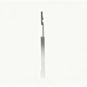
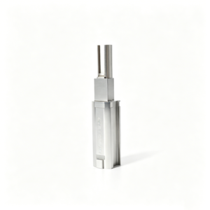
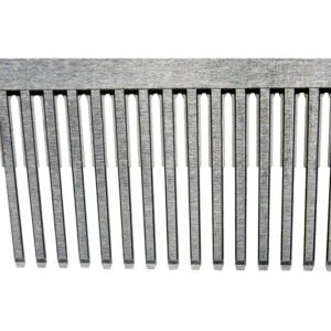
Representative Tooling Components for Carbide Stamping Punch Development





Related Product Catalogue and Quotation






Carbide Stamping Punches: Engineering Advantages
Drawing-led planning keeps critical features, process decisions, and inspection expectations aligned before production begins.
Drawing-Led DFM
Review drawings, models, material requirements, and mating context early to identify manufacturability questions before quotation and production planning.
Critical Feature Control
Define critical dimensions, datums, surface requirements, and tolerance priorities so machining and inspection focus on the features that matter.
Planned Process Routes
Coordinate CNC machining, EDM, grinding, fitting, and heat-treatment sequence around tool access, wire paths, electrode needs, and machining allowance.
Inspection Planning
Agree inspection methods and reporting requirements against the drawing, ensuring final documentation follows the verified order-specific inspection plan.
Revision Visibility
Keep drawing revisions, production questions, and delivery information visible, helping cross-functional teams maintain traceable decisions through the project.
Application Context Review
Consider stamping function, material, quantity, and mating-component context to support a practical manufacturing discussion for carbide stamping punches.
Precision Tooling and Machined Part Families
Explore configurable process and component categories for drawing-driven tooling, mold work, connector applications, and inspected precision parts.

CNC Machining Services
Precision CNC machining services for drawing-based custom machined parts requiring planned milling, turning, EDM, grinding, fitting, and inspection routes. Review critical dimensions, datum references, material requirements, and delivery needs before quotation or production commitments.
Upload a Drawing
CNC Milling
Custom CNC milling services for prismatic parts, plates, inserts, and complex machined features. Tool access, clamping strategy, datum setup, wall geometry, and remaining stock for downstream EDM or grinding are reviewed against the drawing.
Upload a Drawing
CNC Turning
Precision CNC turning services for rotational components such as pins, shafts, sleeves, bushings, and cylindrical tooling details. Diameters, concentricity, runout, thread requirements, and mating features should be defined with suitable datums and inspection criteria.
Upload a Drawing
5-Axis Machining
5-axis CNC machining supports multi-face geometry and angled features where fewer setups can improve feature relationships. The process route depends on part access, fixture stability, tool reach, surface requirements, and the tolerance structure shown on the drawing.
Upload a Drawing
Swiss & Micro Machining
Swiss machining and micro machining address small, slender, and feature-dense components where support, tool deflection, and inspection access matter. Provide critical diameters, lengths, materials, surface requirements, and application context for manufacturability review.
Upload a Drawing
Wire & Sinker EDM
Wire EDM and sinker EDM services support hardened materials, narrow slots, sharp internal geometry, deep cavities, and features with limited milling access. Electrode strategy, wire path, corner conditions, recast-layer considerations, and finishing requirements are reviewed before routing.
Upload a Drawing
Precision Grinding
Precision surface and profile grinding is used to establish controlled flatness, parallelism, profiles, and final-size surfaces. Grinding stock, heat-treatment sequence, datum strategy, and inspection method should be agreed before production.
Upload a Drawing
Mold Core & Cavity Inserts
Precision mold core and cavity inserts are produced from customer drawings and application requirements. Review shutoff geometry, cooling interfaces, steel condition, machining access, EDM requirements, grinding allowance, and critical molding surfaces before manufacture.
Upload a Drawing
Ejector & Ejection Components
Ejector pins, sleeves, and ejection components are configured around mold layout, fit requirements, operating conditions, and mating parts. Specify diameters, clearances, hardness or heat-treatment requirements, surface condition, and critical functional features.
Upload a Drawing
Core Pins, Guide & Locating Components
Core pins, guide pins, and locating components require careful control of fit, alignment, wear surfaces, and mating geometry. Drawings should identify functional datums, critical diameters, material and treatment requirements, and any assembly or mold-context constraints.
Upload a Drawing
Slides, Lifters, Gates & Mold Accessories
Mold slides, lifters, gates, and accessories are supplied as drawing-defined components rather than assumed catalog items. Travel interfaces, shutoffs, wear conditions, material selection, heat treatment, and fitting expectations should be reviewed with the assembly context.
Upload a Drawing
Connector Mold Components
Precision connector mold components support fine-pitch, multi-cavity, and alignment-sensitive tooling applications. Pin geometry, insert relationships, EDM access, polish or finish needs, material condition, and critical dimensions require early drawing and DFM review.
Upload a Drawing
Stamping Die Components
Precision stamping die components, including custom punches and die inserts, are planned around working geometry, material condition, clearance relationships, wear surfaces, and assembly fit. Provide strip or mating-component context where it affects the manufacturing route.
Upload a Drawing
Injection, MIM, CIM & Overmolding Tooling
Injection mold components and tooling for MIM, CIM, and overmolding are evaluated within verified production scope. Drawings should clarify material-flow surfaces, inserts, shutoffs, gates, critical dimensions, heat-treatment sequence, and inspection expectations before commitment.
Upload a Drawing
Machining Materials
CNC machining materials are selected against drawing requirements, functional loads, wear, corrosion exposure, machinability, heat-treatment needs, and inspection criteria. Identify the specified grade, material condition, approved alternatives, and any traceability requirements in the RFQ.
Upload a Drawing
Surface Finishes & Heat Treatment
Surface finishing and heat treatment are coordinated with dimensional priorities, material condition, wear requirements, corrosion exposure, and downstream assembly. Define finish type, target surfaces, masking needs, hardness requirements, and post-treatment inspection expectations.
Upload a Drawing
Quality, Metrology & Documentation
Precision inspection, metrology, and quality documentation are aligned to the order and verified inspection plan. Identify critical dimensions, measurement methods, reporting format, sampling needs, material records, revision status, and traceability requirements before production.
Upload a Drawing
Prototyping & Low-Volume Production
Rapid prototyping and low-volume manufacturing support drawing-driven validation, tooling development, and controlled production quantities. Include the current drawing revision, material, quantity, functional priorities, inspection needs, target date, and any changes from prototype to production intent.
Upload a DrawingMaterials for Carbide Stamping Punches and Die Components

Tungsten Carbide
Used for wear-focused punch tips, die inserts, and fine-feature tooling. Grade selection should consider impact loading, edge geometry, mating clearance, and the drawing-defined inspection requirements before manufacture.

High-Speed Steel
Often considered for punch and die components requiring a balance of toughness and wear resistance. The specified grade, heat treatment, section geometry, and expected loading should guide the project review.

Cold-Work Tool Steel
A practical family for stamping-die blocks, strippers, and supporting details where wear behavior, hardening route, machining allowance, and grinding stock must be coordinated from the approved drawing.

Hot-Work Tool Steel
Considered when the application calls for resistance to elevated-temperature cycling or thermal fatigue. Material designation, heat-treatment requirements, surface condition, and mating-component context require review before quotation.

Powder Metallurgy Steel
May suit selected high-wear or complex tooling requirements when the drawing supports the material choice. SUUXIANG reviews availability, heat-treatment sequence, EDM strategy, grinding access, and inspection needs per project.
Carbide Stamping Punches: Machining, EDM and Grinding


Wire EDM
Wire EDM produces intricate profiles, slots and narrow features where conventional tool access is limited. The wire path, start holes and datum relationship should be reviewed against the functional cutting geometry.

Sinker EDM
Sinker EDM addresses internal forms, sharp details and enclosed geometry that require an electrode-based approach. Electrode strategy, spark allowance and downstream finish requirements are defined during drawing and DFM review.


Fitting Inspection
Fitting and inspection confirm functional relationships between punches, die inserts and mating components. The inspection method and reporting needs are aligned with critical dimensions, revision status and the agreed order documentation.
Carbide Stamping Punches and Compatible Tooling Details

Guide Components
Guide posts, bushings and locating features can be specified to support repeatable die alignment. Provide mating dimensions, datum references, fit expectations and operating context so the component relationship can be reviewed from the drawing.

Locating Features
Custom locating pins, keys and reference surfaces help control part position through stamping and assembly. Their geometry should be coordinated with the strip layout, die-set interfaces, tolerance stack and inspection datum scheme.

Ejection Parts
Ejector pins, sleeves and related ejection details can be considered where release and serviceability affect the tooling design. Submit material, hardness, travel, interface geometry and critical surface requirements for technical review.

Slides and Lifters
Slides, lifters and guided moving details may support complex access or part-release conditions. Drawing review should confirm motion clearance, guiding surfaces, wear interfaces, machining access and the required fitting or inspection approach.

Gates and Accessories
Gates, blocks, plates and other mold or die accessories can be produced as drawing-defined components when they fit the verified process scope. Identify material, heat-treatment sequence, grinding stock and critical dimensions in the RFQ.
About SUUXIANG Precision Manufacturing
SUUXIANG is the international-facing brand of Dongguan SuuXiang Precision Mold Co., Ltd., established in 2010 in Chang’an Town, Dongguan, Guangdong, China. Founded by XiaoCheng Huang, the company helps global teams convert drawings and specifications into inspected custom CNC parts, precision mold components, connector tooling, and carbide stamping punches.
Our workflow begins with DFM and critical-dimension review before quotation or production commitments. CNC machining, EDM, precision grinding, fitting, and inspection are planned around datum strategy, material and heat-treatment requirements, machining access, grinding allowance, and the agreed inspection method.
What distinguishes SUUXIANG is disciplined project coordination: revision control, visible manufacturing decisions, and documentation aligned with the verified inspection plan. For carbide stamping punches and related die components, we focus on the evidence needed to make informed production decisions rather than broad, unsupported capability claims.

Core Capabilities Behind Carbide Stamping Punches
DFM and Datum Review
Before quotation, SUUXIANG reviews the drawing package for critical dimensions, datum relationships, tolerance stack risk, material requirements, and tool access. The discussion identifies questions that can affect carbide stamping punches before a process route or inspection plan is committed.
- Confirm critical-to-quality features and mating requirements
- Review datum strategy and dimensioning logic
- Identify thin sections, sharp transitions, and access constraints
- Align material, heat-treatment, quantity, and delivery inputs

CNC and EDM Planning
Carbide stamping punches may require a coordinated route rather than a single machining operation. SUUXIANG plans CNC, wire EDM, sinker EDM, and electrode work around geometry, feature access, corner conditions, and the drawing’s functional priorities.
- Select processes according to feature geometry and access
- Plan wire paths and electrode requirements early
- Consider machining sequence around heat-treatment requirements
- Keep process choices tied to documented drawing revisions

Grinding and Fitting Strategy
Grinding strategy is evaluated with the required surfaces, datum references, finishing allowances, and assembly context in view. For punch and die relationships, SUUXIANG treats fitting as a controlled tooling activity, with attention to the interfaces that influence clearance and functional alignment.
- Define grinding stock within the agreed process route
- Relate finished surfaces to functional datums
- Review punch-to-die and component interface requirements
- Escalate unclear assembly conditions before production

Inspection and Revision Control
Inspection planning begins with the drawing and agreed critical features, not a generic checklist. SUUXIANG coordinates measurement methods, reporting expectations, order documentation, and revision visibility so delivered carbide stamping punches can be checked against the current approved requirement.
- Link inspection focus to critical dimensions and datums
- Agree reporting and documentation requirements before production
- Maintain visibility of drawing and revision status
- Match final records to the verified inspection plan

Why Choose SUUXIANG for Carbide Stamping Punches
A drawing-led workflow helps align process planning, inspection, and revision communication before production commitments.
← Swipe left or right to view →
Carbide Stamping Punches: From Drawing to Inspection
A controlled workflow that aligns DFM, process planning, critical dimensions and documentation before delivery commitments are made.
RFQ and Drawing Review
We review 2D drawings, 3D models, material, quantity, application context, delivery target and inspection requirements to define quotation inputs and open technical questions.
DFM and Process Planning
Critical dimensions, datums, tolerance stack, machining access, heat-treatment sequence, EDM needs and grinding allowance are assessed before the manufacturing route is confirmed.
Material and Blank Preparation
The approved material requirement and part configuration guide blank preparation, traceability planning and process sequencing for the specified carbide stamping punches or related die components.
Machining, EDM and Grinding
CNC machining, wire or sinker EDM, precision grinding and finishing are combined as required, with tool access, electrode strategy and grinding stock managed through production.
Fitting and Inspection
Components are checked against the agreed drawing revision and inspection plan, focusing on critical features, surface requirements, mating relationships and required reporting evidence.
Packing and Shipment Coordination
Accepted parts are protected for transport and released with order-matched documentation, revision visibility and shipment coordination aligned to the confirmed delivery requirements.
How to Source Carbide Stamping Punches With SUUXIANG
Provide the drawing package and production priorities early so DFM, process planning, inspection expectations and quotation can be aligned before release.
Send the Drawing Package
Submit the current 2D drawing and 3D model when available, identifying revision status, application context, mating parts and any features requiring clarification.
Define Material and Quantity
State the required carbide grade or approved material requirement, heat-treatment needs where applicable, prototype or production quantity, and anticipated repeat demand.
Identify Critical Requirements
Mark critical dimensions, datums, surface requirements, functional fits, burr or edge priorities, and any tooling conditions that affect machining, EDM or grinding strategy.
Confirm Quality and Timing
Specify inspection methods, report or traceability requirements, acceptance priorities, packaging needs and target delivery date for a responsible technical and commercial review.
Review the Manufacturing Plan
Evaluate SUUXIANG’s DFM feedback, proposed process route, inspection approach, revision questions and quotation details before authorizing production of carbide stamping punches.
Carbide Stamping Punches: Quality Documentation and Certification Evidence

Customer-Testimonial Verification Status
No customer testimonial is published until project outcome, customer permission, and supporting records have been verified.
No production, delivery, dimensional, or tool-life outcome is claimed here without an approved project record.
SUUXIANG publishes customer names and endorsements only with explicit permission from the responsible project contact.
Carbide Stamping Punches FAQ
Practical answers for engineering, quality, and procurement teams planning drawing-driven punch and die components.
What information should I send for a carbide stamping punch RFQ?
Can SUUXIANG make carbide stamping punches from my drawing?
What is the MOQ for custom carbide stamping punches?
How should I plan sampling and lead time for precision punches?
How do I specify carbide grade and heat treatment?
What inspection reports can be requested with carbide stamping punches?
How are drawings, revisions, and IP handled during the project?
Can you arrange international shipping for custom punch orders?
The Complete Buyer’s Guide to carbide stamping punches
A practical decision framework for specifying carbide stamping punches, evaluating drawing-based suppliers, controlling total tooling risk, and avoiding material, tolerance, inspection, and lead-time mistakes before production.
1. What Are Carbide Stamping Punches?
1. Carbide stamping punches are wear-critical cemented-carbide die components that enter a workpiece to pierce holes, blank profiles, trim edges, or perform localized forming. Their working tip mates with a die insert; clearance, alignment, and edge condition determine whether the cut is stable.
2. A punch holder locates and retains the punch, while a stripper supports stock control and helps remove material from the punch on the return stroke. This component set is used in progressive dies, transfer dies, and compound dies, although the exact load path and guidance arrangement depend on the tool design.
3. Buyers should consider carbide when abrasive or high-volume work, small cutting features, or sustained edge stability justify evaluating a harder, less-tough material than conventional tool steel. Grade selection, punch geometry, backing support, die clearance, strip guidance, and impact loading must be reviewed together; carbide is not a universal substitute for steel. Reference: https://langdi-precision.com/carbide-punches-die-inserts-for-stamping-for-connector-industry
2. How Carbide Punch Technology Evolved
Precision grinding and EDM expanded the practical range of carbide punch geometry by enabling controlled flats, diameters, cutting edges, and intricate profiles. The drawing should define the wire path, corner condition, finish requirement, and inspection method where those details affect function.
For repeatable stamping, carbide punches must be evaluated as part of a coordinated system: grade selection, die clearance, alignment, surface condition, and inspection all affect dimensional consistency. Avoid treating nominal dimensions alone as sufficient evidence of functional fit.
3. Types of Carbide Stamping Punches
Six configurations cover most drawing-based carbide stamping punches. Selection begins with the cutting or forming job, then checks retention, guidance, clearance, and replaceability within the die set.
| Configuration | Operating Job | Key Drawing Detail | Compatibility Check |
|---|---|---|---|
| Round/shaped | Pierce features | Profile and datum | Stripper guidance |
| Blade/profile | Shear contours | Radii and relief | Lateral support |
| Stepped/headed | Locate or retain | Shoulders or head seat | Holder fit |
| Tipped/forming | Cut or shape | Joint or radii | Load path and timing |
Piercing And Profile Punches
Round and shaped piercing punches create holes, slots, or keyed openings; the drawing must define cutting profile, land, length, and datum relationship. Edge chipping and slug-pulling exposure make stripper guidance and die clearance essential.
Blade and profile punches shear long or irregular contours; specify corner radii, wire-EDM relief, and profile tolerance. Ask whether the die plate supports the blade against lateral deflection.
Retention And Load Configurations
Stepped punches locate multiple working diameters or shoulders; define every transition radius, step length, and fit diameter. Stress concentration at shoulders requires confirmation of guide and stripper support.
Headed punches transmit load through a retained head; specify head geometry, seat, shank fit, and overall projection. Ask whether the punch holder clamps the head without bending the working end.
Composite And Forming Punches
Carbide-tipped steel-body punches place wear resistance at the cutting end while using a steel shank for mounting; define joint geometry and concentricity. Tip cracking or joint failure requires a compatible load path and replacement strategy.
Forming punches bend, coin, emboss, or shape rather than simply pierce; specify radii, contact faces, and forming travel. Ask whether die timing, backing, and material springback are controlled.
4. Carbide Grades and Workpiece Materials
Cemented-carbide selection is a balance, not a hardness contest. Grade choice should be reviewed against the stamped stock, edge-life target, press conditions, and failure mode expected for the carbide stamping punches.
| Option | Wear Resistance | Impact Tolerance | Typical Decision |
|---|---|---|---|
| Fine-grain carbide | High | Moderate | Stable, abrasive production work |
| Tougher carbide grade | Moderate to high | Higher | Shock-sensitive punching conditions |
| Tool steel | Lower | Higher | Development or impact-prone features |
Balance Grade Properties
Higher hardness and wear resistance help retain a cutting edge, while greater cobalt-binder content generally improves toughness and impact tolerance. Compressive strength alone does not prevent chipping when alignment or stripping is unstable.
Match The Stamping Load
Material thickness, tensile strength, plating or coating, burr limit, stroke rate, and impact loading should be stated in the RFQ. Thin connector stock may favor edge retention; interrupted loading or misalignment risk may require a tougher grade.
Compare Carbide And Steel
Solid carbide is typically selected for demanding wear and dimensional stability, but it is less forgiving of shock than tool steel. Tool-steel alternatives can suit development work or impact-prone features when the expected wear rate is acceptable.
Request Material Evidence
Material certificates should identify the supplied grade and heat or batch where available. Traceability links incoming material, drawing revision, inspection records, and replacement-punch investigations when wear or fracture occurs.
5. Customizing Carbide Stamping Punches
Custom carbide stamping punches begin with a controlled drawing package, not cosmetic options. SUUXIANG reviews geometry, production route, inspection evidence, and revision status before confirming a manufacturable scope.
Define The Drawing Package
2D drawings should identify units, material, heat-treatment condition, and all critical-to-quality features. A matching 3D model helps clarify profiles, reliefs, and nonstandard transitions.
Datum A, B, and C should locate features in the functional assembly order. Mark punch tip dimensions, concentricity needs, and unilateral limits where function requires them.
- Latest 2D drawing and native or neutral 3D model
- Critical dimensions and datum references
- Material, condition, and quantity
Call Out Functional Interfaces
Edge geometry must state corner radii, land length, chamfer, or edge-break requirements rather than relying on a visual model. The shank, keyway, retaining feature, and mounting orientation must match the holder or punch plate.
Mating die inserts, stripper details, and clearance assumptions should accompany the RFQ when they govern fit or tool access.
- Tip profile and edge condition
- Shank or mounting interface
- Mating-component drawings
Review DFM And Revisions
DFM review should test grinding access, EDM wire paths, electrode strategy, inspection datums, and feasible tolerances before release. Surface-finish and coating callouts need the functional surface and post-process dimensional expectation.
Revision control requires a drawing revision, change description, and written disposition of work in progress. Application data—stock material, thickness, press conditions, and expected stroke demand—helps identify risks without assuming performance.
- Identify revision on every submitted file
- Confirm coating timing and masked surfaces
- Record approved DFM changes
6. Quality Elements That Protect Tool Life
Documented material, geometry, and inspection controls determine whether a punch repeats its first-off condition through production. For carbide stamping punches, tool life is protected at interfaces—not by hardness alone.
Carbide Lot And Geometry
Documented carbide grade, supplier lot, and grain structure—where available—should accompany the drawing review. Uncontrolled grade substitution can change toughness, wear behavior, and chipping risk.
Critical punch geometry includes cutting profile, corner radii, land, and relief. Relief that is incorrect or inconsistent increases rubbing, galling, and dimensional drift.
Edge And Surface Control
Specified edge preparation prevents a nominally sharp corner from becoming a fragile stress concentrator. The agreed edge condition should match stock material, clearance, and impact loading.
Grinding should establish final geometry and surface finish after the relevant heat-treatment route. EDM surfaces require recast-layer review or removal where the drawing or application makes it critical.
Mating Fit And Inspection
Measured concentricity, working diameter, profile, and length verify the punch against its functional datums. Inspection methods should be defined before release, including suitable gauges, optical measurement, or CMM checks.
Verified fit with the mating die insert confirms clearance and alignment as an assembly condition. Recording results by drawing revision helps isolate wear, chipping, and change-control issues.
7. Choosing a Carbide Stamping Punch Manufacturer
A capable manufacturer demonstrates control before purchase-order release, not through capability slogans. For carbide stamping punches, compare the evidence behind each promise against the drawing’s critical features and delivery risks.
| Evaluation Area | Evidence To Request | Marketing Assertion To Avoid |
|---|---|---|
| DFM | Annotated review | We handle any drawing |
| Quality | Report and traceability | Strict inspection |
| Lead time | Route and milestone plan | Fast delivery |
Engineering Review
The first drawing review should identify datums, critical dimensions, carbide grade, EDM or grinding route, and inspection method.
A written DFM response exposes whether questions are application-specific or merely a quotation template.
- Request annotated drawing feedback
- Confirm revision ownership
- Ask how files are protected
Process And Inspection Evidence
Material traceability should connect the supplied carbide to the ordered grade and lot documentation.
Inspection evidence should name instruments, sampling logic, report format, and how nonconforming results are contained before shipment.
- Material certificate or lot record
- First-article inspection report
- Measurement-equipment capability
Release And Delivery Control
Sample approval should define accepted dimensions, surface condition, and documentation before repeat production.
Change control should require written approval for drawing, material, route, or inspection-plan changes; packaging and export updates should remain traceable.
- Controlled sample approval
- Revision-change notification
- Packing and shipment status
8. Common Carbide Stamping Punches Buying Mistakes
Before release, carbide stamping punches should be reviewed as a die-system interface, not a standalone purchase. Most avoidable failures begin with incomplete input, ambiguous acceptance criteria, or a quote comparison that hides downstream risk.
Grade And Strip Data
First, do not select a grade by hardness alone or omit strip grade, thickness, temper, coating, and production rate. Ask: Which grade balances wear resistance and fracture risk for this strip and impact condition?
Geometry And Die Interface
Second, a size tolerance without functional datums, punch-to-die clearance, or alignment information cannot define a reliable interface. Ask: Which datums control the tip, shank, and mating die, and what clearance and guide condition apply?
Coating Inspection And Cost
Third, do not treat coating as a cure-all, approve parts without inspection criteria, or compare unit price alone. Ask: What coating limit, inspection method, report, replacement risk, and total landed cost must the quotation include?
9. From Drawing to Production Release
One production release should convert the drawing into a controlled manufacturing and inspection package. For carbide stamping punches, the workflow must connect application loading, die interfaces, and replenishment decisions.
Define The Application
First, state strip material, thickness, press conditions, expected life, and whether the punch serves connector tooling or a general stamping die.
Two mating details matter early: die clearance and guide/alignment condition; both affect grade selection and chipping risk.
Build And Review The Package
One RFQ package should include the 2D drawing, 3D model when available, revision level, material or grade requirement, heat-treatment condition, datums, and critical dimensions.
Before machining, obtain DFM feedback on wire paths, EDM electrodes, grinding stock, measurement access, and any geometry needing a design decision.
Approve, Validate, Replenish
First articles or samples should be approved against the agreed inspection plan before a repeat order. Validate punches in the actual die for fit, edge condition, burr behavior, and failure mode.
Every revision needs a new identifier and disposition of prior stock. For prototypes and low volumes, preserve the approved setup; for repeat production, define reorder quantity, documentation, and delivery trigger.
10. Carbide Stamping Punches Pricing and Lead Time
Three variables usually dominate cost: carbide grade and blank size, geometric complexity, and the tolerance/surface requirement. Tight features raise grinding, wire-EDM or sinker-EDM time; coatings, inspection scope, quantity, and expedite priority also change the quote.
±0.005 mm features may require more controlled datum setup and measurement than general-profile work. A low unit price can therefore be misleading when a small lot needs custom electrodes, dedicated inspection, or first-article reporting.
One complete RFQ should identify material grade, blank dimensions, drawing revision, quantity, coating, critical dimensions, report requirements, and required receipt date. SUUXIANG should confirm price and lead time only after drawing review and process planning.
| Illustrative planning tier — not a SUUXIANG quote | Relative price driver | Typical planning lead-time band |
|---|---|---|
| Simple profile; 1–10 pieces | Blank and setup dominate | 1–3 weeks |
| Tight or complex profile; 1–10 pieces | EDM, grinding, inspection dominate | 2–5 weeks |
| Repeat geometry; 50+ pieces | Setup spreads across quantity | Quote after capacity review |
Send Your Carbide Stamping Punches Drawing for Review
Upload your drawing, material, quantity, critical dimensions, inspection requirements, and target date for a quote-ready manufacturing discussion.