
Mold Cooling Channel Inserts, Planned From Your Drawing
SUUXIANG reviews critical dimensions, machining access, EDM needs, and inspection requirements for custom mold cooling channel inserts before quotation.
Representative Custom Components for Mold Cooling Channel Inserts


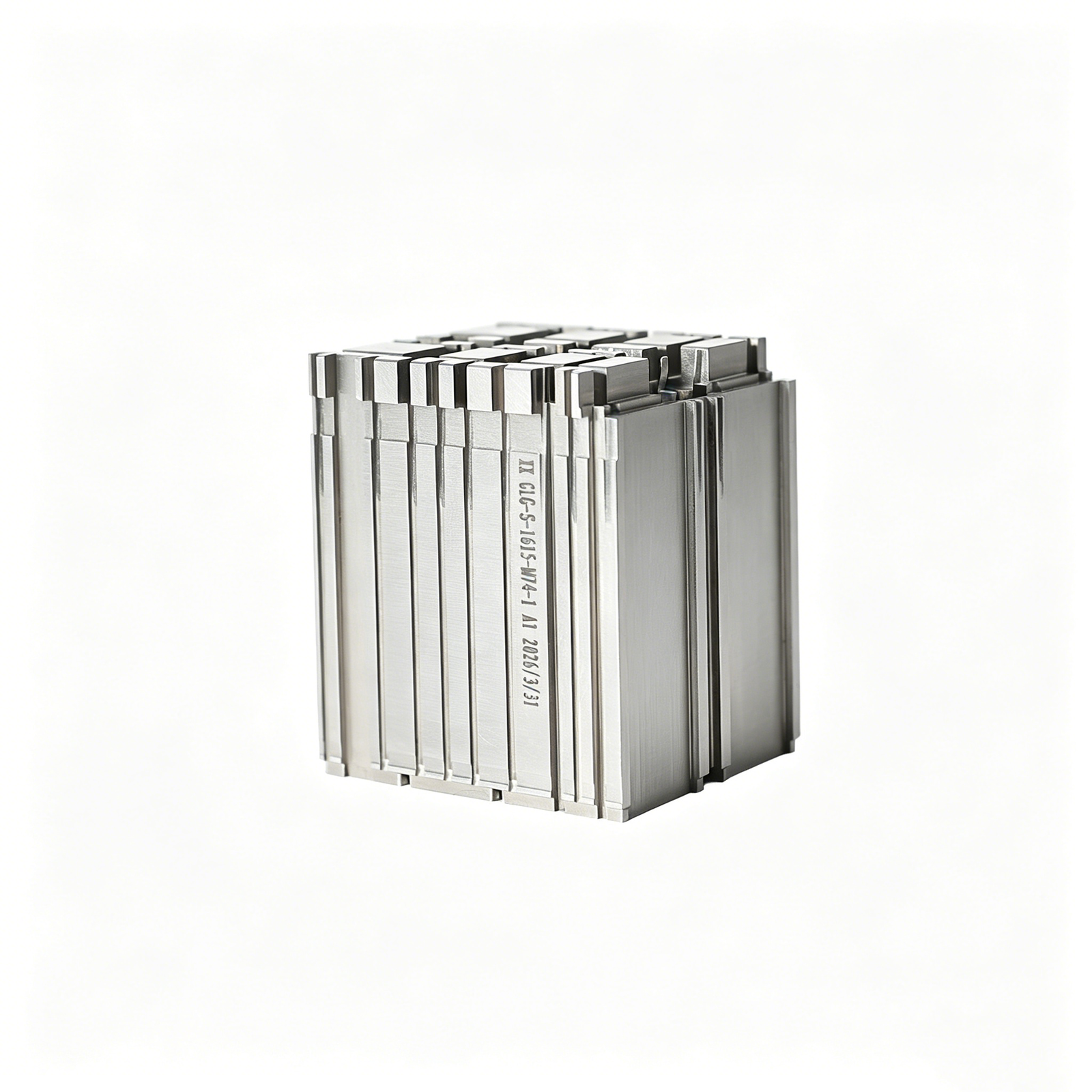


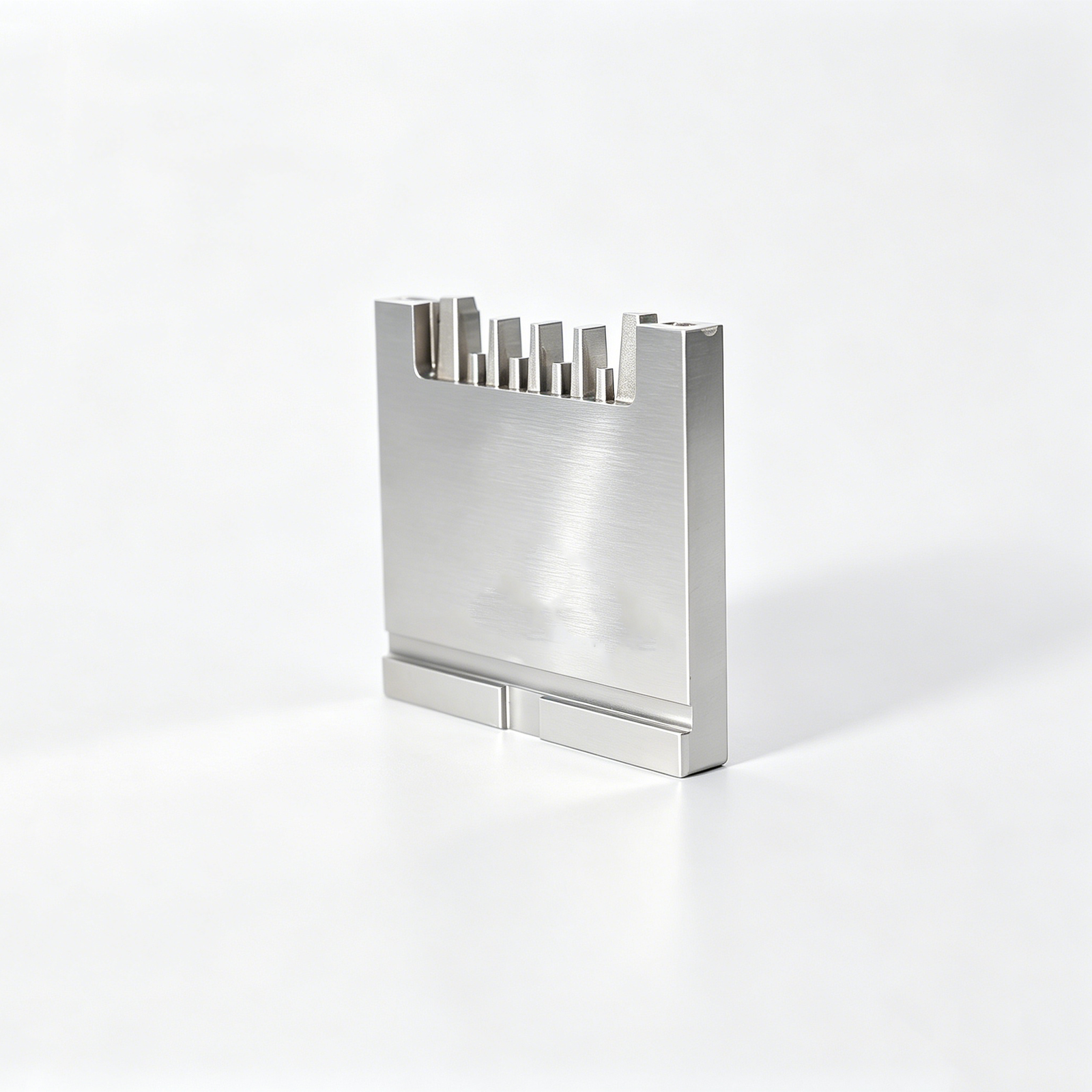
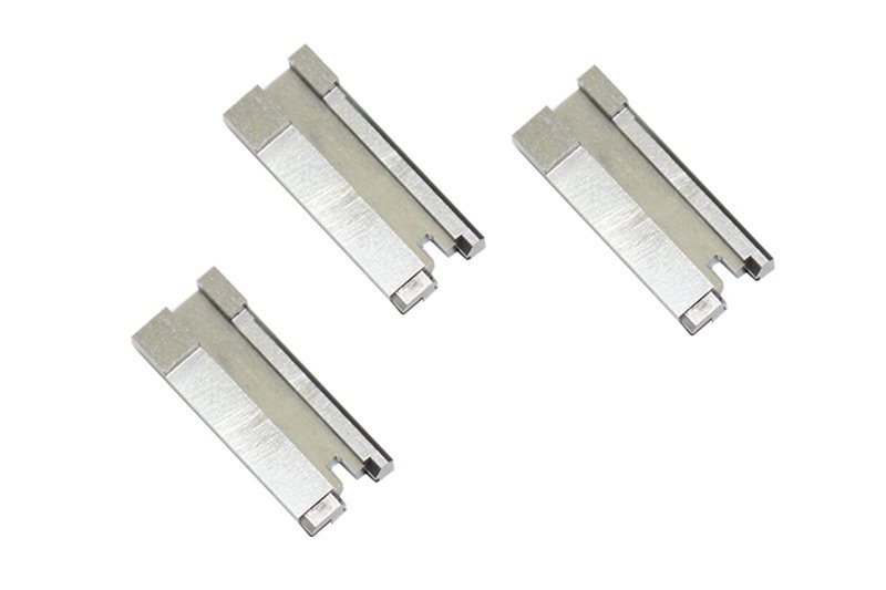
Related Component Families and Drawing-Based Quotations






Engineering Advantages for Mold Cooling Channel Inserts
Plan critical features, process routes and inspection evidence before production commitments.
DFM Before Quotation
Review drawing details, coolant-path intent, machining access and potential manufacturing risks before the process route and quotation are defined.
Critical Dimensions Planned
Identify functional dimensions, datum relationships, surface priorities and tolerance-stack concerns so inspection methods align with the component’s intended mold function.
Coordinated Process Routes
Combine CNC machining, EDM, precision grinding and fitting according to geometry, tool access, heat-treatment sequence and required finishing conditions.
Inspection From the Start
Define practical measurement points, reporting expectations and acceptance criteria early, helping final documentation match the drawing revision and inspection plan.
Visible Revision Control
Keep drawing revisions, technical clarifications and delivery coordination visible throughout the project to reduce avoidable changes between approval and production.
Cooling-Channel Inserts and Tooling Families
Drawing-driven component families for cooling-channel tooling, mold builds, connector applications and controlled prototype or low-volume production.

CNC Machining Services
Precision CNC machining services translate approved drawings into custom tooling components, with process planning focused on cooling-channel access, critical dimensions, material requirements, and inspection expectations before production is committed.
Upload a Drawing
CNC Milling Services
Custom CNC milling services support prismatic inserts, plates, manifolds, and mold details where cooling passages, sealing faces, datums, and tool access must be resolved from the drawing.
Upload a Drawing
CNC Turning Services
Precision CNC turning services produce rotational cooling-channel tooling features such as sleeves, bushings, cores, plugs, and threaded interfaces, with attention to concentricity, wall thickness, mating geometry, and downstream finishing.
Upload a Drawing
5-Axis Machining
5-axis CNC machining supports angled, contoured, and multi-face cooling-channel inserts where conventional setups create access limits or datum-transfer risk. Toolpath strategy and inspection points should be reviewed against the functional geometry.
Upload a Drawing
Swiss & Micro Machining
Swiss machining and micro machining address small-diameter pins, sleeves, nozzles, inserts, and locating features used around compact cooling or connector tooling. Specify critical diameters, straightness, material condition, and handling requirements in the RFQ.
Upload a Drawing
Wire EDM Services & Sinker EDM Services
Wire EDM and sinker EDM services produce narrow slots, internal profiles, sharp features, deep cavities, and hardened-tooling geometry that milling cannot reach efficiently. Electrode strategy, wire path, recast-layer expectations, and finishing allowance require review.
Upload a Drawing
Precision Grinding
Precision surface and profile grinding establishes flatness, parallelism, profile accuracy, and controlled stock removal on hardened inserts and mating components. Drawings should identify functional surfaces, datums, grinding allowance, and surface requirements.
Upload a Drawing
Mold Core & Cavity Inserts
Precision mold core inserts and mold cavity inserts can incorporate cooling-channel interfaces, shutoff features, cavity geometry, and insert-to-base datums. SUUXIANG reviews material, heat-treatment sequence, machining access, EDM needs, and inspection requirements before manufacture.
Upload a Drawing
Ejector & Ejection Components
Ejector pins, sleeves, and ejection components must work with bore geometry, lubrication, thermal conditions, and movement clearance in the mold. Provide mating dimensions, hardness requirements, surface priorities, and any cooling-channel proximity concerns.
Upload a Drawing
Core Pins, Guide & Locating Components
Core pins, guide pins, and locating components establish repeatable alignment between mold elements and related tooling details. Critical requirements commonly include diameter control, concentricity, straightness, fit class, material condition, and mating-part relationships.
Upload a Drawing
Slides, Lifters, Gates & Mold Accessories
Mold slides, lifters, gates, and accessories combine moving interfaces, wear surfaces, cooling constraints, and assembly relationships. Drawing review should confirm travel geometry, shutoffs, lubrication provisions, machining access, and inspection methods for critical interfaces.
Upload a Drawing
Connector Mold Components
Precision connector mold components support high-density cavities, terminal-forming features, fine pitch geometry, and repeatable alignment. Quote packages should define resin or application context, mating dimensions, critical surfaces, material, heat treatment, and inspection priorities.
Upload a Drawing
Stamping Die Components
Precision stamping die components include punches, dies, guides, inserts, and wear elements made to drawing-defined geometry. Process planning considers material condition, heat-treatment sequence, grinding stock, EDM features, clearance relationships, and dimensional verification.
Upload a Drawing
Injection, MIM, CIM & Overmolding Tooling
Injection, MIM, CIM, and overmolding tooling components are evaluated against the applicable process, part geometry, material behavior, cooling needs, and assembly interfaces. SUUXIANG confirms the achievable route only after reviewing current project requirements.
Upload a Drawing
Machining Materials
CNC machining materials are selected from the drawing, application, mechanical demands, corrosion exposure, heat-treatment route, and inspection needs. State the specified grade, approved substitution rules, material documentation requirements, and quantity when requesting a quotation.
Upload a Drawing
Surface Finishes & Heat Treatment
Surface finishing and heat treatment must be planned around functional surfaces, dimensional change, wear, release, corrosion resistance, and post-process grinding or EDM. Define the required treatment, finish area, masking needs, and verification expectations.
Upload a Drawing
Quality, Metrology & Documentation
Precision inspection, metrology, and quality documentation are aligned to drawing-defined critical dimensions, datums, measurement methods, revision status, and reporting requirements. Identify first-article, dimensional report, material, or traceability expectations before production begins.
Upload a Drawing
Prototyping & Low-Volume Production
Rapid prototyping and low-volume manufacturing support drawing-driven validation parts, bridge tooling, replacement components, and controlled production quantities. Supply the current revision, quantity, material, functional priorities, delivery target, and inspection needs for feasibility review.
Upload a DrawingMaterials for Mold Cooling Channel Inserts

Pre-Hardened Tool Steel
A practical option for many mold cooling channel inserts where stable machining and moderate wear resistance are required. Selection depends on cooling layout, finishing needs, dimensional priorities, and whether the supplied condition suits the application.

Through-Hardening Tool Steel
Considered for inserts facing higher wear or compressive loading when the specified heat-treatment route supports the required geometry. DFM review checks machining allowance, distortion risk, grinding stock, and critical dimensions before processing.

Corrosion-Resistant Tool Steel
Evaluated for cooling channel inserts exposed to moisture-sensitive service conditions or corrosion concerns. Grade choice must be matched to coolant practice, surface requirements, heat treatment, and the customer’s documented material specification.

High-Conductivity Alloy Materials
Used conditionally where thermal response is a key design consideration and the application supports the material choice. SUUXIANG reviews wear demands, joining interfaces, machining behavior, and inspection needs against the approved drawing.

Engineering Steel Alloys
Suitable for custom insert concepts that require a defined balance of machinability, strength, and downstream finishing. Material confirmation considers geometry, EDM access, grinding sequence, mating components, and required quality documentation.
Mold Cooling Channel Inserts: Machining and EDM Processes

CNC Milling
CNC milling establishes insert profiles, pockets, coolant manifolds, and accessible channel features. Tool access, wall thickness, datum surfaces, and machining allowance are reviewed to support stable subsequent EDM, grinding, and fitting operations.

CNC Turning
CNC turning supports rotational cooling-channel components, plugs, sleeves, and cylindrical interfaces where concentricity and sealing-related geometry matter. Drawing review identifies datum relationships, thread requirements, material condition, and inspection points before routing.

Wire EDM
Wire EDM produces precise through-features, narrow profiles, and difficult-to-machine insert geometry after material condition and wire path are evaluated. The route considers start-hole access, corner requirements, critical dimensions, and downstream fitting or grinding stock.

Sinker EDM
Sinker EDM forms cavity details, deep ribs, and internal geometry beyond practical cutter access. Electrode strategy, finish expectations, datum control, and EDM allowance are planned so mold cooling channel inserts can be finished and inspected against the drawing.


Fitting Inspection
Fitting and inspection verify mating relationships, critical dimensions, channel-related interfaces, and specified reporting needs. SUUXIANG aligns the inspection method and final documentation with the approved drawing revision, order requirements, and verified inspection plan.
Mold Cooling Channel Inserts: Hardware and Finishing Options

Guide Elements
Guide pins, bushes, and wear-guidance interfaces can be supplied where their fit, material, hardness, lubrication needs, and mating geometry are clearly defined on the drawing or assembly data.

Locating Features
Dowel holes, locating shoulders, keys, and reference faces help establish repeatable insert position. Datum selection, fit class, assembly sequence, and inspection points should be agreed before machining.

Threaded Fasteners
Screws, plugs, retaining hardware, and threaded closures may be coordinated for mold cooling channel inserts when thread standards, sealing requirements, torque considerations, and purchased-part specifications are provided.

Sealing Components
O-rings, sealing plugs, and related interfaces can be considered for coolant circuits. Groove dimensions, coolant medium, pressure conditions, material compatibility, and leak-check expectations require drawing review.

Surface Protection
Protective oil, corrosion-control treatment, marking, or specified finishing can be applied when compatible with the material, surface requirement, assembly use, and subsequent cleaning process.

Protective Packaging
Custom packing, separated compartments, rust prevention, and identification labels help protect critical surfaces and preserve revision traceability during shipment. Define handling, labeling, and documentation requirements with the RFQ.
About SUUXIANG Precision Manufacturing
SUUXIANG is the sole international-facing public brand of Dongguan SuuXiang Precision Mold Co., Ltd., established in 2010 in Chang’an Town, Dongguan, Guangdong, China. Its founder and legal representative is XiaoCheng Huang. We help engineering, sourcing and quality teams turn drawings and specifications into inspected CNC-machined parts, precision mold components, connector tooling and die components.
Our work combines CNC milling and turning, multi-axis machining, wire and sinker EDM, precision grinding, fitting and inspection. For mold cooling channel inserts and related tooling, the production route is selected from the drawing, critical dimensions, datum strategy, material condition, machining access and reporting requirements—not from a generic catalogue.
What distinguishes SUUXIANG is disciplined technical coordination before production commitments. We review DFM risks, tolerance stacks, EDM or grinding needs, heat-treatment sequence and inspection methods with the project requirements in view, then maintain revision and delivery information through the manufacturing workflow.

How Mold Cooling Channel Inserts Are Planned and Made
DFM and Datum Review
Each mold cooling channel insert project begins with the drawing, model, application context, and quality requirements. SUUXIANG reviews critical dimensions, datum relationships, wall conditions, cooling interfaces, material requirements, and revision status before a process route is discussed or quoted.
- Identify critical-to-quality dimensions and functional datums
- Review cooling interfaces, sealing features, and adjacent mold components
- Confirm material, heat-treatment, surface, and quantity requirements
- Flag manufacturability risks before production commitments

CNC and EDM Access Strategy
Channel geometry, corner detail, internal features, and local hardness can determine whether CNC machining, wire EDM, sinker EDM, or a combined route is appropriate. Access is assessed early so electrode strategy, wire paths, machining sequence, and reference surfaces remain aligned.
- Assess tool access for drilled, milled, and EDM-created features
- Plan wire paths and electrode locations around functional geometry
- Sequence machining around heat treatment and finishing needs
- Preserve stable references for downstream operations

Grinding and Fitting Allowances
Precision mold cooling channel inserts often rely on controlled stock for grinding and fitting after earlier operations. SUUXIANG plans allowances against the drawing’s functional dimensions, mating conditions, and surface requirements, helping teams avoid removing critical material before final adjustment and verification.
- Define grinding stock before final machining stages
- Review mating faces, shutoff areas, and locating features
- Coordinate fitting needs with dimensional priorities
- Align final finish with the inspection plan

Inspection and Revision Control
Inspection planning should reflect the features that affect assembly, coolant performance, and part quality. SUUXIANG aligns measurement methods and requested documentation with the order, while keeping drawing revisions, inspection expectations, and delivery information visible through the project workflow.
- Link inspection points to critical dimensions and datums
- Clarify reporting and traceability requirements before production
- Maintain visible revision control through the order workflow
- Match final documentation to the verified inspection plan

Why Choose SUUXIANG for Mold Cooling Channel Inserts
Compare the engineering controls that help align drawing review, process planning, inspection, and revision handling before production.
← Swipe left or right to view →
Mold Cooling Channel Inserts: From Drawing to Shipment
Each project follows a drawing-led route that keeps critical dimensions, process decisions, inspection requirements, and revision information visible before production commitments.
Review Drawing Requirements
Review 2D drawings, 3D models, material, quantity, cooling layout, critical dimensions, datums, surface requirements, inspection needs, and delivery targets before quotation.
Plan Process Route
Define DFM actions, machining access, drilling or EDM strategy, heat-treatment sequence, grinding stock, fitting requirements, and inspection approach for the approved revision.
Machine Core Features
Produce applicable insert features through CNC milling, turning, multi-axis machining, drilling, and micro-machining, while maintaining defined datum relationships and machining allowance.
Finish EDM And Grinding
Apply wire EDM, sinker EDM, precision grinding, and fitting where required, checking electrode strategy, wire paths, surface requirements, and feature accessibility.
Inspect Pack And Coordinate
Verify parts against the agreed inspection plan, match documentation to the order, protect finished surfaces in packing, and coordinate shipment information with the customer.
How to Source Mold Cooling Channel Inserts
Move from drawing review to approved production with clear requirements, documented decisions and coordinated delivery.
Submit Your Technical Package
Share the 2D drawing, available 3D model, application context, quantity and target delivery date so the team can begin a focused technical review.
Define Critical Requirements
Confirm material, heat treatment, critical dimensions, datums, surface requirements and inspection documentation, including cooling-channel geometry or mating-component details that influence manufacturability.
Review DFM and Feasibility
Evaluate machining access, EDM or grinding needs, tolerances, inspection approach and revision status before quotation, sample planning or production commitments are finalized.
Approve Production Coordination
Approve the agreed technical route and quality plan, then receive coordinated progress information as machining, fitting, inspection and delivery preparation proceed against the confirmed revision.
Quality Documentation for Mold Cooling Channel Inserts
Illustrative Project Scenarios for Mold Cooling Channel Inserts
SUUXIANG identified an inaccessible drill path during drawing review before release. After the revised insert layout was approved, the first article matched our critical datums, and we avoided a four-week tooling rework cycle.
For 24 cooling insert components, the team maintained revision visibility across CNC, EDM, grinding, and inspection. The dimensional report clearly tied each measured feature to our drawing, which shortened our supplier-quality review.
The quotation discussion focused on material, heat treatment, grinding stock, and the six dimensions that controlled fit. That early DFM exchange helped us release a buildable drawing and receive the pilot parts on our requested date.
Mold Cooling Channel Inserts FAQ
Practical RFQ, quality, delivery and revision-control guidance for drawing-driven tooling components.
What information should I send for mold cooling channel inserts?
Is there a minimum order quantity for mold cooling channel inserts?
Can I order a sample before production of mold cooling channel inserts?
How do you evaluate lead time for a custom mold insert?
Which materials and heat treatments can be used?
What inspection reports can be supplied with mold cooling channel inserts?
How are shipping, payment and packaging handled for precision inserts?
How do you protect IP and control drawing revisions?
Complete Buyer’s Guide to mold cooling channel inserts
Use this decision framework to compare cooling-insert designs, materials, manufacturing routes, supplier controls, and cost drivers—while avoiding specification gaps that create thermal imbalance, leakage risk, delayed validation, or avoidable tooling revisions.
1. What Are Mold Cooling Channel Inserts?
A mold cooling channel insert has two essential interfaces: its working face forms or supports the cavity or core region, while its external geometry locates it in the mold base. Internal passages, bubblers, or thermally conductive paths connect to the tool’s coolant circuit so heat can be extracted near a localized hot spot.
Cooling design affects cycle stability, part quality, and throughput. Uneven mold temperatures can contribute to differential shrinkage, warpage, sink marks, and unstable dimensions; the insert is therefore a thermal-control component, not merely a replaceable metal block.
The design review should ask whether a dedicated insert can place heat transfer nearer the problem area while preserving tool strength, sealing, coolant flow, service access, and datum control better than reworking the entire mold. SUUXIANG should assess the drawing, molded-part geometry, existing circuit, critical quality symptoms, and inspection requirements before selecting a manufacturable route.
2. From Drilled Lines to Conformal Cooling
Two traditional routes—straight-drilled passages and machined inserts assembled around intersecting lines—remain practical where tool access reaches the heat load. Baffles, bubblers, or conductive inserts can extend cooling into selected deep areas without changing the whole insert architecture.
Three conditions commonly expose their limits: deep cores, curved geometry, uneven wall sections, and hot spots isolated from a drill axis. These conditions can leave unequal steel temperatures and require a channel path, circuit layout, or insert split chosen from the cavity geometry rather than copied from a standard layout. https://www.aimprocessing.com/blog/designing-cooling-channels-in-injection-molds-a-combination-of-art-and-science
Metal additive manufacturing enables internal channels that curve with a cavity or core profile, including paths that conventional drilling cannot create. That freedom must be weighed against pressure drop, cleanability, material route, post-processing, validation, and expected production benefit; conformal cooling is an application-specific option, not an automatic upgrade. https://madisongroup.com/can-conformal-cooling-improve-your-part-quality
3. Types of Mold Cooling Channel Inserts
Six channel architectures cover most insert decisions. Select them after reviewing cavity geometry, available steel, heat-load location, circuit access, and maintenance requirements.
| Type | Suitable Geometry | Cooling Reach | Serviceability | Main Limitation |
|---|---|---|---|---|
| Straight-drilled | Open plates | Direct | High | Cannot follow contours |
| Baffled/bubbler | Deep pockets | Extended | Moderate | Flow restrictions |
| Spiral/helical core | Cylindrical cores | Tip-focused | Low | Complex machining |
| High-conductivity | Localized hot spots | Conductive spread | High | Does not add flow |
| Assembled cooling | Split inserts | Targeted | Moderate | Sealing interfaces |
| Conformal-channel | Curved complex cores | Profile-following | Low | Specialized manufacture |
Architecture Comparison
A 2D section should confirm channel reach before selecting an architecture. The best route balances thermal access with toolmaking, sealing, and cleaning needs.
A service plan should identify removable plugs, baffles, and interfaces. Hidden passages may improve reach but complicate flushing and repair.
Selection By Tool Constraints
A straight-drilled route suits open, accessible steel and simple heat patterns. Baffles, bubblers, and helical cores extend reach into deep or slender features.
An assembled or conformal route suits restricted geometry when conventional drilling cannot approach the hot area. Verify pressure drop, sealing, inspection access, and replacement strategy during drawing review.
4. Materials for Mold Cooling Channel Inserts
Material choice sets the insert’s heat path, mechanical reserve, and maintenance burden. It does not replace a channel layout that controls distance to the cavity, flow balance, pressure drop, and cleanout access.
| Material Family | Heat Transfer | Durability And Maintenance | Typical Fit |
|---|---|---|---|
| Tool steel | Moderate | High wear resistance; repairable | General molded parts |
| PH stainless | Moderate | Better corrosion resistance | Water-exposed tooling |
| Copper alloy | High | Lower wear reserve | Localized hot spots |
| Additive alloy | Material-dependent | Post-process verification required | Complex internal channels |
Tool Steel Baseline
Tool steels provide hardness, wear resistance, polishability, and familiar weld-repair routes for many cavity and core inserts.
Hardened steel transfers heat less readily than copper alloys, so verify hot spots through cooling analysis rather than assuming material alone will solve them.
Stainless And Copper Tradeoffs
Precipitation-hardening stainless grades suit water-exposed service where corrosion resistance and useful hardness must coexist.
Copper alloys move heat quickly but usually trade wear resistance, polish retention, and repair practicality; protect them where abrasion, aggressive resin, or high clamp loads matter.
Additive Alloy Considerations
Additively processed tool-steel alloys enable internal channel geometry unavailable to drilling, but powder route, heat treatment, density, finish, and inspection require project-specific review.
Conformal channels can improve access to complex thermal zones; their pressure drop and flow distribution still require validation. https://madisongroup.com/can-conformal-cooling-improve-your-part-quality
5. Custom Mold Cooling Channel Insert Options
A custom cooling insert begins with the controlled drawing, not a catalog geometry. SUUXIANG reviews the insert envelope, cavity or core interface, coolant circuit, and critical datums before selecting a feasible machining, EDM, grinding, and inspection route.
Define The Physical Interface
2D drawings should define the insert envelope, locating faces, mounting holes, threads, seals, cavity or core boundaries, surface finish, heat treatment, coatings, and identification marks. A matching 3D model exposes tool access, intersecting passages, and electrode or wire-EDM requirements.
One datum scheme must govern replacement inserts. Keep interface dimensions, thread forms, O-ring grooves, connector locations, and permanent part revision marks controlled so a future insert fits without reworking its mating mold plate.
Specify Cooling And Operating Data

Cooling-channel callouts should state diameter, path, plug locations, inlet and outlet connection type, and allowable modifications. Supply coolant medium, target temperature, flow or pressure information, molding resin, expected thermal load, and any leakage-test requirement.
Revision-controlled files should include the latest 2D drawing, 3D model, material specification, quantity, inspection requirements, and mating-component context. SUUXIANG can then identify unresolved tolerances, sealing risks, and inspection points before production.
- Latest 2D drawing and 3D model
- Material, hardness, coating, and finish requirements
- Coolant connection and operating conditions
- Inspection plan and revision identifier
6. Quality Elements That Protect Cooling Performance
Drawing-defined datums and a documented inspection plan make cooling performance auditable before an insert enters a mold. Review each feature as a heat-transfer, flow, and sealing requirement—not as an isolated machining dimension.
Datums And Cooling Walls
Specified datums should locate channel centerlines, port faces, and cavity-side surfaces in one measurement strategy. Controlled channel-to-surface spacing and minimum wall thickness reduce hot zones, breakthrough risk, and thermal-fatigue cracking.
Ports, Seals, And Surfaces
Defined port geometry must match the intended fittings, thread engagement, and coolant path. Verified sealing faces, O-ring grooves, deburred intersections, and suitable internal surface condition help prevent leaks, restricted flow, and corrosion initiation.
Validation And Traceability
Order-specific pressure and leak tests should state the test medium, pressure, hold time, acceptance criterion, and result. Material identification, heat-treatment status when specified, hardness results, and dimensional reports connect the delivered insert to its revision and inspection plan.
7. Choosing a Mold Cooling Channel Insert Supplier
A capable supplier turns cooling requirements into a controlled manufacturing and inspection plan. For mold cooling channel inserts, compare evidence from the released drawing, tolerance stack, and coolant-path requirements—not a generic capability list.
| Evaluation Area | Supplier Question | Useful Evidence |
|---|---|---|
| DFM | Which tolerances drive the route? | Marked drawing review |
| Cooling path | How is the internal channel checked? | Validation record |
| Metrology | Which datums govern inspection? | Inspection plan |
| Changes | How are revisions released? | Revision log |
Test The DFM Response
A 2D drawing and 3D model should trigger questions on datums, tool access, EDM strategy, grinding stock, sealing interfaces, and pressure-drop assumptions.
Ask for marked-up DFM feedback before release. It should identify manufacturable alternatives without changing critical cooling intent.
Verify Process And Material Control
Material traceability should connect the ordered grade, received stock, heat-treatment route, hardness requirement, and final part identification.
Additive internal channels need a different validation plan than drilled or EDM-produced passages. Ask which process is proposed and how inaccessible features are verified.
Require Evidence And Change Discipline
Inspection planning should name critical dimensions, datums, instruments, channel-validation method, report format, and acceptance criteria.
Prototype and low-volume orders need the same revision control as production work. Confirm who approves drawing changes, how deviations are recorded, and which documents ship with parts.
8. Common Mold Cooling Channel Insert Mistakes
Cooling failures often begin before machining, when the drawing leaves thermal, hydraulic, or interface requirements undefined. Release only after each cooling insert decision has an owner and measurable acceptance evidence.
Price Without Operating Data
Lowest insert price can omit coolant type, inlet temperature, flow rate, and circuit arrangement; the result is an insert that fits yet cannot stabilize the hot zone. Ask: What coolant conditions and allowable temperature variation must this circuit meet?
Geometry Without Hydraulic Review
Conformal paths are not automatically superior, and tight turns or long paths can raise pressure drop and reduce delivered flow. Ask: What flow, pressure-drop limit, and thermal comparison support this channel layout?
Unreachable tolerances on internal paths or sealing lands can create scrap, leakage, or costly redesign. Ask: Which dimensions are critical, how will they be made, and what inspection method verifies them?
Seals, Corrosion, And Validation
Missing O-ring groove, plug-thread, surface-finish, or assembly details can cause coolant leaks; untreated water can corrode channels and restrict flow. Ask: What sealing specification, coolant chemistry, and maintenance condition applies?
Skipping pressure, leak, and molding validation can defer failure until launch. Ask: Which pre-release tests, acceptance limits, and inspection records are required?
9. Launching a Cooling Insert Project
A controlled release sequence turns a cooling concept into a verified mold component. For mold cooling channel inserts, freeze decisions only after thermal, manufacturing, inspection, and molding criteria have named owners.
Review Inputs And Thermal Concept
Stage 1 starts with the part drawing, 3D model, mold layout, resin grade, wall sections, cycle target, coolant temperature, flow and pressure limits. The mold owner identifies hot zones, cavity interfaces, available connections, and acceptance criteria.
Stage 2 documents the thermal concept against those inputs. The team records circuit routing, inlet and outlet identification, sealing interfaces, service access, and any molding-machine constraints.
DFM And Drawing Freeze
Stage 3 converts the concept into DFM: datums, critical dimensions, machining access, EDM or grinding allowances, tolerances, material, heat treatment, and surface requirements. SUUXIANG should return exceptions or unresolved assumptions for written disposition.
Stage 4 freezes the revision-controlled drawing package and inspection plan. The buyer supplies quantity, delivery need, reporting format, and the approved revision authority.
Verification And Production Release
Stage 5 uses a prototype or first article to verify dimensional results and pressure integrity against the agreed test method. Records should identify test medium, pressure, duration, measurement points, and pass criteria.
Stage 6 completes molding trials against cycle time, part temperature, warpage, sink, and cosmetic requirements. Release follows approved trial evidence, closed revisions, traceable records, and confirmed production quantity.
10. Mold Cooling Channel Inserts: Pricing and Cost
A complete 2D drawing, 3D model, and defined quantity make cooling-insert quotations comparable because they establish geometry, revision, and the required process route. Material grade, insert envelope, tolerance, channel geometry, finishing, heat treatment, inspection, and validation each affect setup and unit cost.
Lead time must be confirmed after drawing review. Complex EDM, grinding, heat-treatment, or validation routes require project-specific planning. A complete RFQ reduces requoting when it identifies CTQ dimensions, datums, surface requirements, cooling connections, report format, and mating-component context.
| Project tier | Main cost drivers | Quotation basis | Planning lead time |
|---|---|---|---|
| Prototype, 1–2 pieces | Programming, setup, material, first-article inspection | One-off route and inspection plan | Project-specific after drawing review |
| Simple repeat, 3–20 pieces | Setup spread across quantity; machining time | Stable revision and material | Project-specific |
| Complex channel insert | EDM electrodes, wire paths, deep features, sealing interfaces | DFM review and process sequence | Project-specific |
| Tight-tolerance or validated insert | Grinding, heat-treatment sequence, metrology, flow or leak checks | Defined CTQs and acceptance evidence | Project-specific |
Upload Your Mold Cooling Channel Inserts Drawing
Submit drawings, material, quantity, critical dimensions, inspection needs, and target date for a DFM-led RFQ assessment.