
Mold Vent Inserts Built From Your Drawings
Send your drawings for DFM review, process planning, and inspection-focused production of custom mold vent inserts.
Representative Mold Vent Insert Components




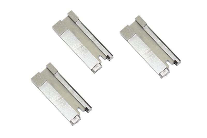





Related Components and Drawing-Based Quotation
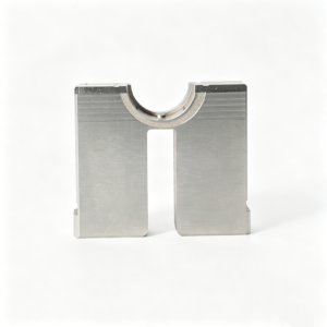

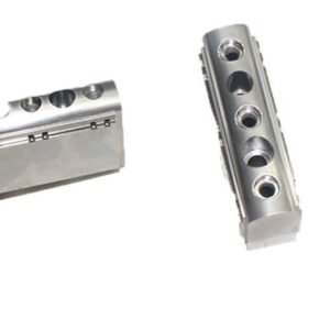


Mold Vent Inserts for Complex Venting Requirements
SUUXIANG aligns drawing review, process planning, critical dimensions, EDM, grinding, inspection, and revision control before production commitments.
Drawing-Led DFM Review
Review vent locations, part geometry, datums, tool access, and critical interfaces before quotation to identify manufacturability questions early.
Process Route Planning
Plan CNC machining, wire EDM, sinker EDM, grinding, and fitting around the insert geometry, functional surfaces, and agreed delivery requirements.
Critical Dimension Focus
Identify critical-to-quality dimensions, datum relationships, and tolerance-stack risks so manufacturing and inspection priorities are visible from the start.
EDM and Grinding Coordination
Coordinate electrode strategy, wire paths, heat-treatment sequence, and grinding stock where intricate vent features require controlled finishing routes.
Inspection Plan Alignment
Define appropriate measurement methods, reporting needs, and documentation expectations against the drawing and verified inspection plan before production begins.
Revision Visibility
Keep drawing revisions, technical decisions, and delivery information visible throughout project coordination to reduce avoidable version-control uncertainty.
Mold Vent Inserts and Related Components
Drawing-driven component families for venting areas, mold function, and the process controls needed to manufacture and inspect them.

CNC Machining Services
Precision CNC machining services for drawing-based mold components and custom machined parts. Process planning considers datums, critical dimensions, material condition, tool access, machining allowance, and inspection requirements before production commitments are made.
Upload a Drawing
CNC Milling
Custom CNC milling services for prismatic mold inserts, venting features, plates, and locating details. Reviews address cutter access, corner radii, depth-to-width ratios, datum references, and remaining stock for EDM or grinding where required.
Upload a Drawing
CNC Turning
Precision CNC turning services for rotational parts such as pins, sleeves, bushings, and guide elements. Drawings should identify functional diameters, concentricity relationships, surface requirements, material, heat-treatment sequence, and inspection priorities.
Upload a Drawing
5-Axis Machining
5-axis CNC machining supports complex faces, angled features, and multi-sided mold details with fewer repositioning steps where the geometry and inspection plan justify it. Tool reach, fixture strategy, datum control, and finishing access are reviewed from the model and drawing.
Upload a Drawing
Swiss & Micro Machining
Swiss machining and micro machining support small, detailed parts where diameter control, slender geometry, cross features, and handling require a suitable process route. Evaluate material, functional dimensions, burr limits, surface requirements, and measurement method with the RFQ.
Upload a Drawing
Wire & Sinker EDM
Wire EDM services and sinker EDM services address sharp internal geometry, hardened materials, deep ribs, narrow venting details, and profiles that are impractical to mill conventionally. Electrode design, wire path, flushing, recast-layer considerations, and finishing requirements need review.
Upload a Drawing
Precision Grinding
Precision surface and profile grinding provides controlled flatness, parallelism, profile form, and final-size adjustment for mold components. Grinding stock, heat-treatment condition, datum sequence, surface requirements, and measurement criteria should be defined before routing.
Upload a Drawing
Mold Core & Cavity Inserts
Precision mold core inserts and mold cavity inserts are configurable, drawing-based components for forming surfaces, shutoffs, venting regions, and replaceable tooling areas. Review steel selection, heat treatment, parting-line strategy, EDM access, grinding allowance, and critical dimensions before manufacture.
Upload a Drawing
Ejector & Ejection Components
Ejector pins, sleeves, and related ejection components are produced to the functional requirements of the mold assembly. Specify working diameters, clearance relationships, hardness condition, surface expectations, stroke-related features, mating details, and inspection needs.
Upload a Drawing
Core Pins, Guide & Locating Components
Core pins, guide pins, and locating components support repeatable alignment and forming function within a mold. Drawings should establish datum relationships, fit classes, mating-component context, material and heat-treatment requirements, and the dimensions that control assembly performance.
Upload a Drawing
Slides, Lifters, Gates & Mold Accessories
Mold slides, lifters, gates, and accessories are configurable components requiring assembly-aware process planning. Provide movement interfaces, shutoff surfaces, angle relationships, material condition, lubrication or wear considerations, mating parts, and dimensional inspection priorities.
Upload a Drawing
Connector Mold Components
Precision connector mold components support fine-pitch, multi-cavity, and alignment-sensitive connector tooling. RFQs benefit from clear cavity or core context, pin geometry, critical spacing, datum scheme, material and heat-treatment requirements, EDM or grinding needs, and inspection expectations.
Upload a Drawing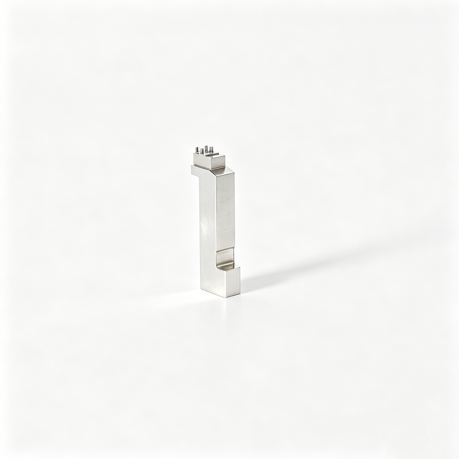
Stamping Die Components
Precision stamping die components include drawing-based inserts, punches, dies, guide elements, and related custom parts. Manufacturing review considers cutting-edge geometry, clearance relationships, wear surfaces, steel condition, grinding sequence, and dimensions that govern die assembly.
Upload a Drawing
Injection, MIM, CIM & Overmolding Tooling
Injection mold components for MIM, CIM, and overmolding tooling are evaluated within verified production scope. Provide the molding process, material or feedstock context, parting and venting requirements, thermal or wear demands, insert function, and any mating or assembly information.
Upload a Drawing
Machining Materials
CNC machining materials are selected against drawing requirements, functional loads, corrosion exposure, wear, thermal conditions, machinability, and downstream heat treatment. State the required material grade or approved equivalent, material condition, traceability needs, and applicable customer specifications.
Upload a Drawing
Surface Finishes & Heat Treatment
Surface finishing and heat treatment are specified according to function rather than assumed as standard. Identify hardness range, treatment sequence, coating or finish requirements, surface roughness, masking areas, distortion concerns, and which dimensions require final verification after processing.
Upload a Drawing
Quality, Metrology & Documentation
Precision inspection, metrology, and quality documentation are planned around the order’s critical dimensions and acceptance criteria. Define report format, sampling or full-inspection expectations, datum references, measurement method needs, material records, revision status, and traceability requirements in advance.
Upload a Drawing
Prototyping & Low-Volume Production
Rapid prototyping and low-volume manufacturing support drawing-led evaluation, fit checks, tooling development, and controlled production requirements. Share quantity, target date, material, dimensional priorities, finish requirements, revision status, and the evidence needed for acceptance.
Upload a DrawingMaterials for Mold Vent Inserts

Pre-Hardened Tool Steel
A practical choice for vent inserts requiring balanced machinability and service durability. Pre-hardened grades can support CNC, EDM, and grinding routes while reducing the need for post-machining heat treatment, subject to drawing requirements.

Hardened Tool Steel
Considered for mold vent inserts exposed to abrasion, repeated contact, or demanding production conditions. Heat-treatment requirements, finishing allowance, EDM strategy, and critical dimensions should be reviewed together before the manufacturing route is confirmed.

Corrosion-Resistant Steel
Used where resin behavior, humidity, storage conditions, or corrosion risk influence tooling decisions. Grade selection must account for required hardness, polish or surface condition, vent geometry, and the inspection criteria stated on the drawing.

High-Speed Tool Steel
May be evaluated for localized wear resistance in demanding vent insert applications. Its suitability depends on geometry, heat-treatment requirements, machining access, grinding stock, and whether the design requires EDM-produced fine venting features.

Porous Metal Material
Can be considered for venting zones that need gas release through a specialized insert structure. Selection requires project-specific review of resin, pressure conditions, insert support, cleaning expectations, dimensional requirements, and mating-component design.
Mold Vent Inserts Manufacturing Processes

CNC Milling
CNC milling establishes insert profiles, pockets, vent land features and mounting geometry from approved drawings. Tool access, datum locations and machining allowance are reviewed to support stable finishing and controlled fit within the mold assembly.


Wire EDM
Wire EDM produces precise through-profiles, narrow slots and complex venting contours when conventional cutting access is limited. Wire path, start-hole location, corner requirements and remaining stock should be defined with the drawing review.

Sinker EDM
Sinker EDM is considered for deep, fine or enclosed cavity details that require an electrode-based approach. Electrode strategy, burn condition, subsequent finishing allowance and critical surfaces are aligned with the specified component function.


Fitting and Inspection
Fitting and inspection confirm the relevant interfaces, critical dimensions and specified surface conditions against the agreed plan. Measurement records, revision status and any required reporting are coordinated with the order requirements before delivery.
Supporting Hardware and Identification for Mold Vent Inserts

Locating Features
Dowel holes, locating flats, shoulders, or datum references can help position vent inserts consistently within the mold. Define mating relationships, critical dimensions, and inspection priorities to support repeatable assembly.

Fastening Interfaces
Threaded holes, counterbores, clamp faces, and retention features can be machined where the mold design requires them. Provide fastener specifications, access constraints, and assembly loads for a practical process review.

Anti-Rotation Keys
Keys, flats, or orientation features can prevent incorrect installation of asymmetric mold vent inserts. Their geometry should be coordinated with the pocket, wire path, machining access, and intended maintenance procedure.

Identification Marking
Part numbers, revision identifiers, cavity references, or orientation marks can support traceability during fitting and service. Specify marking location, character requirements, and whether the mark must remain outside functional surfaces.

Inspection References
Datum marks, witness surfaces, or designated measurement features can clarify how critical dimensions are verified. Align these references with the drawing, mating components, inspection method, and required reporting before release.
About SUUXIANG Precision Manufacturing
SUUXIANG is the international-facing brand of Dongguan SuuXiang Precision Mold Co., Ltd., established in 2010 in Chang’an Town, Dongguan, Guangdong, China. XiaoCheng Huang is the founder and legal representative. We help global engineering and sourcing teams convert drawings, models, and specifications into inspected precision parts, including mold vent inserts and connector-tooling components.
Our work integrates DFM review with CNC milling and turning, multi-axis machining, EDM, precision grinding, fitting, and inspection. For each project, we review critical dimensions, datums, machining access, material and heat-treatment requirements, venting geometry, and inspection expectations before production commitments are made.
What distinguishes SUUXIANG is disciplined project control rather than a generic catalog promise. We align the process route, revision status, inspection plan, and delivery requirements to the order. Send a 2D drawing, available 3D model, quantity, material, quality priorities, and target date to begin a focused technical review.

Drawing-Review Workflow for Mold Vent Inserts
DFM Before Process Commitment
SUUXIANG reviews mold vent insert drawings, models, material requirements, and critical dimensions before quotation. The discussion identifies datums, venting interfaces, surface priorities, tool access, and potential tolerance conflicts so the proposed route reflects the actual component function.
- Confirm critical-to-quality dimensions and datum references
- Review cavity geometry, vent paths, and mating interfaces
- Identify material, heat-treatment, and surface requirements
- Clarify inspection and delivery expectations early

CNC, EDM, and Grinding Strategy
Complex venting geometry often requires more than one process. SUUXIANG evaluates CNC machining access alongside wire EDM, sinker EDM, and precision grinding needs, then plans the sequence around geometry, allowance, hardness condition, and surfaces that must remain functionally accurate.
- Match machining access to feature depth and geometry
- Assess wire path and electrode strategy where needed
- Reserve grinding stock for critical bearing surfaces
- Sequence machining around heat-treatment requirements

Fitting for Functional Interfaces
Mold vent inserts must work within an assembled tool, not only meet isolated dimensions. SUUXIANG plans fitting around locating faces, shutoff areas, mating components, and serviceability, helping teams address practical assembly risks before production rather than after trial.
- Review locating and bearing-face relationships
- Consider shutoff, clearance, and flash-risk interfaces
- Account for removable or replaceable insert requirements
- Align fitting priorities with the drawing revision

Inspection and Revision Visibility
Inspection planning follows the agreed drawing and identified critical features. SUUXIANG maintains visible revision and delivery coordination through the project, so dimensions, reporting expectations, and documentation remain aligned with the order and verified inspection plan.
- Define inspection methods for critical dimensions
- Align reports with agreed quality requirements
- Maintain traceable drawing-revision communication
- Coordinate delivery information against the order

Why Choose SUUXIANG for Mold Vent Inserts
A drawing review and inspection-aligned workflow for custom vent insert requirements.
← Swipe left or right to view →
Mold Vent Inserts: From Drawing Review to Delivery
A controlled workflow aligns DFM, machining, EDM, grinding, fitting, inspection, and revision visibility before parts move to packing and delivery coordination.
Review RFQ Inputs
We review the 2D drawing, 3D model, quantity, material, application, critical dimensions, surface requirements, inspection needs, and requested delivery date.
Plan Process Route
The team confirms datum strategy, machining access, venting geometry, EDM or wire-cut requirements, heat-treatment sequence, grinding stock, and inspection approach before commitment.
Machine Critical Features
CNC milling, turning, multi-axis machining, wire EDM, and sinker EDM are applied according to the approved drawing and process plan.
Grind and Fit Components
Grinding and fitting establish functional interfaces, controlled clearances, and mating relationships while preserving agreed datums, revision status, and critical feature requirements.
Inspect Against Requirements
Inspection follows the order-specific plan, focusing on critical dimensions, surface requirements, and required documentation so results remain traceable to the applicable revision.
Pack and Coordinate Delivery
Verified parts are packed for shipment, with delivery coordination and final documentation aligned to the confirmed order, inspection expectations, and customer communication requirements.
Work With SUUXIANG on Mold Vent Inserts
Move from drawing review to controlled production with clear technical inputs, documented decisions and revision visibility.
Submit Your Drawing Package
Send 2D drawings, available 3D models, application context, quantity, material, heat-treatment requirements, delivery target, and any inspection or reporting expectations.
Define Critical Requirements
Identify critical dimensions, datums, surface requirements, venting locations, mating interfaces, and acceptance criteria so the review addresses functional risks before quotation.
Review DFM and Quotation
Evaluate proposed machining, EDM, grinding, fitting, and inspection routes together with manufacturability feedback, assumptions, revision status, and quotation scope.
Approve Samples When Needed
For projects requiring validation, align sample quantity, inspection method, documentation, and acceptance criteria before releasing mold vent inserts for production.
Coordinate Production and Delivery
Confirm the approved revision, production schedule, inspection plan, packaging needs, and delivery information while maintaining traceable communication through completion.
Mold Vent Inserts: Certification and Quality Documentation
Mold Vent Inserts: Approved Customer Feedback
Customer project references are published only after documented customer approval confirms the applicable drawing revision, application context, inspection scope, and project outcome.
Approved project references may describe how drawing review, EDM or grinding planning, and inspection documentation supported a defined component requirement.
References remain subject to customer approval, confidentiality requirements, and verification of the project details presented.
Mold Vent Inserts FAQ
Practical answers for drawing review, sampling, inspection, delivery, and technical coordination.
What information should I send for a mold vent insert RFQ?
Can SUUXIANG make mold vent inserts from a custom drawing?
What MOQ applies to custom mold vent inserts?
Should I request a sample before ordering production quantities?
Which process is used for a mold vent insert: CNC, EDM, wire EDM, or grinding?
How should I plan lead time for custom vent inserts?
Can I request an inspection report with my order?
How are technical drawings and design revisions controlled?
How are mold vent inserts packed and shipped internationally?
The Complete Buyer’s Guide to Mold Vent Inserts
Use this practical decision framework to specify mold vent inserts, compare venting approaches and materials, evaluate drawing-based suppliers, and avoid design, quality, maintenance, and sourcing mistakes that undermine molded-part performance.
1. What Are Mold Vent Inserts?
Two functions define mold vent inserts: they are dedicated, removable mold components that create controlled escape paths for air and process gases as the melt fills a cavity. Their vent geometry must pass gas while limiting resin leakage and flash.
Six mold features must be considered together: parting-line vents, ejector-pin venting, porous media, inserts, gates and runners, and cooling. Gate position and runner balance determine where air is driven; cooling can change local freeze-off and therefore the time available for gas to escape.
One vent insert is justified when the likely air trap is remote from a practical parting line, lies in a deep rib or detailed cavity feature, or needs serviceable local venting without reworking the main tool steel. Inadequate venting can compress and heat gas, contributing to short shots, burn marks, surface blemishes, and unstable filling from shot to shot.
2. Evolution of Mold Venting Solutions
Two mating mold surfaces historically supplied the first controlled escape route: shallow parting-line clearances, plus gaps around ejector or removable insert interfaces. That economical assumption remains valid only where the last-to-fill area coincides with an accessible split; it can leave deep ribs and isolated cavity pockets dependent on difficult-to-control clearances (https://designplastics.com/blog/understanding-injection-molding-venting-consideration-guide).
Lamellar vent inserts extended venting across shaped areas through stacked or modular elements, while porous-metal inserts offered distributed gas paths where a conventional groove could not reach. These choices became more relevant as tighter geometries, intricate cavities, and cosmetic surfaces reduced tolerance for flash, witness marks, polishing damage, and trapped-gas defects (https://www.ermannobalzi.com/eng/lamellar-mold-venting-insert-s51.php).
Vacuum-assisted systems added active evacuation for cases where passive paths alone are inadequate during rapid filling. Modern drawing review should therefore identify the original venting concept, datum scheme, fit, vent path, material condition, and maintenance history before sourcing a replacement; copying legacy insert geometry without those records can change sealing or vent performance (https://www.swcpu.com/blog/venting-in-injection-molding).
3. Types of Mold Vent Inserts
Format selection starts with the last-to-fill air trap, available steel section, and cosmetic-side requirement. A vent insert should provide a controlled gas path without becoming the sole answer to a restricted exhaust route.
| Format | Capacity And Strength | Surface Effect And Pairing |
|---|---|---|
| Grooved solid | Moderate; high strength | Possible witness; pair parting vent |
| Lamellar | High; edge support needed | Possible line; pair runner vent |
| Porous metal | Distributed; lower strength | Texture risk; pair backup vent |
| Channels | Moderate; geometry-dependent | Witness risk; pair ejector vent |
| Core/cavity | Localized; application-dependent | Insert line; pair vacuum if needed |
Grooved Solid Inserts
Solid inserts use machined grooves to carry gas to a relief path. They suit accessible local traps and permit straightforward cleaning or replacement.
Lamellar Inserts

Lamellar stacks vent through controlled interfaces between layers. They suit broad or irregular zones, but require supported edges and periodic cleaning.
Porous-Metal Inserts
Porous metal vents through a permeable matrix across the insert face. It serves inaccessible traps, while lower strength and contamination demand backup venting.
Insert-Piece Channels

Insert-piece channels route gas along fitted insert boundaries or dedicated grooves. They suit ribs and localized features, but witness lines require cosmetic review.
Core And Cavity Inserts
Core or cavity inserts combine replaceable geometry with vent paths at damage-prone features. They should pair with parting-line, ejector, or vacuum venting when flow-end gas volume exceeds local capacity.
4. Materials for Mold Vent Inserts
Material choice sets the balance between vent performance and insert life. The drawing should identify resin, cavity location, expected cycles, cleaning exposure, finish, and dimensional priorities before a grade is released.
| Material Family | Strength | Primary Selection Check |
|---|---|---|
| Hardened tool steel | Wear; polishability | Abrasive resin; cycle count |
| Stainless steel | Corrosion resistance | Resin gases; cleaning exposure |
| Copper alloy | Thermal conductivity | Cooling need; protected location |
| Sintered porous metal | Distributed venting | Pore clogging; backing support |
Solid Tool Steels
Hardened tool steels suit high-wear groove inserts and retain edge definition under repeated clamping. Higher hardness improves wear resistance but raises finishing effort and can reduce machinability.
Corrosion And Thermal Options
Stainless grades are practical where corrosive resins, humid storage, or aqueous cleaning threaten rust. Copper alloys can improve local heat transfer, but their lower wear resistance limits use at sealing or abrasive-contact edges.
Porous Metal Decisions
Sintered porous metals vent through a controlled pore network where grooves cannot reach the gas trap. Pore stability depends on resin residue, cleaning method, support geometry, and avoiding aggressive polishing that smears openings.
5. Custom Mold Vent Inserts and Features
Two drawing categories prevent costly ambiguity: functional venting features and cosmetic requirements. For mold vent inserts, define the gas path, sealing interfaces, installation orientation, and replacement intent before release.
| Feature | Drawing Definition | Release Check |
|---|---|---|
| Vent path | Pattern, depth, datum, tolerance | Resin and flow context |
| Fit and orientation | Pocket fit, taper, flats, locating | Assembly direction |
| Wear interface | Contact surfaces and replacement boundary | Service access |
Define Functional Geometry
Three items need explicit dimensions: insert envelope, vent-groove pattern and depth, and lamella arrangement or pore specification. Tie each critical feature to a datum scheme and state its tolerance, including any taper, locating shoulder, or mounting thread.
One resin and process note should identify material, fill direction, likely air-trap location, and molding conditions. SUUXIANG can review tool access, EDM strategy, grinding stock, and inspectability against the supplied drawing.
Control Fit And Orientation
Two orientation controls are commonly drawing-critical: anti-rotation flats and keyed locating features. Specify the mating-pocket datum, fit requirement, insertion direction, and whether press, slip, or retained mounting is intended.
One replaceable wear interface needs its service boundary defined. Call out sealing land, contact face, fastener access, and permitted replacement relationship rather than relying on an assembly sketch alone.
Separate Appearance Requirements
Two finish zones should be distinguished: venting and sealing surfaces require functional surface requirements, while exposed non-contact faces may need only cosmetic finishing. Marking, edge breaks, and visible texture should never override vent-path performance or fit.
One DFM review before release can identify inaccessible grooves, fragile lamellae, unsuitable pore assumptions, or tolerance stacks that conflict with the selected process route.
6. Construction Quality of Mold Vent Inserts
100% dimensional conformance on a print still does not prove a vent insert will work. Sealing contact, connected vent paths, edge condition, cleanliness, and mold fit-up determine whether it vents without flash and remains serviceable.
Contact And Vent Geometry
Two interfaces require separate control: the seating and sealing faces, and every intended vent land or channel. Inspect profile, flatness, location to datums, and vent continuity; nominal outside dimensions alone cannot reveal a blocked or uneven path.
Edges And Surface Condition
100% accessible vent edges should be checked for burrs, rolled material, EDM residue, and damage that changes clearance or prevents full contact. Specify finish only where it supports sealing, flow, release, or service—not as a cosmetic substitute for geometry.
Verification And Mold Fit-Up
One traceable inspection record should link the drawing revision, material and heat-treatment evidence, hardness result where specified, and measured critical features. Confirm fit in the actual pocket, contact pattern, vent outlet freedom, and clean assembly condition before production release.
7. Choosing a Mold Vent Inserts Supplier
Two suppliers can machine identical geometry yet deliver different venting results. Evaluate the supplier’s drawing review, process controls, and evidence before comparing unit price.
| Evaluation Area | Ask For | Warning Sign |
|---|---|---|
| Engineering review | Venting-function questions | Quote follows geometry only |
| Process route | CNC, EDM, grinding plan | No datum or allowance discussion |
| Quality release | Inspection and sample plan | Generic quality statement |
| Change control | Written revision confirmation | Verbal changes only |
Test Engineering Understanding
1 RFQ should state resin, gate location, end-of-fill areas, mold temperature, expected cycle conditions, and flash limits. Ask how the supplier will relate vent path, insert fit, surface finish, and cleaning access to that function.
- Request a datum and critical-dimension review
- Ask whether EDM, grinding, or fitting controls sealing faces
- Confirm porous material is specified by source and grade
Require Production Evidence
3 evidence sets matter: material identification, heat-treatment records when specified, and dimensional inspection matched to drawing datums. For porous inserts, require incoming identification and a sample-validation plan rather than assuming permeability proves finished-part fit.
- First-article inspection report
- Revision-controlled drawing acknowledgement
- Agreed corrective-action response path
Compare Delivery Discipline
2 delivery risks are unmanaged revisions and transit damage. Confirm a named communication route, change-approval checkpoint, protective packaging for edges and porous surfaces, and a realistic lead-time commitment tied to the approved scope.
8. Common Mold Vent Inserts Buying Mistakes
Two drawing reviews prevent most vent-insert failures: assess where air and gas finish the flow path, then match the insert to molding conditions. Release criteria should define both vent performance and replaceable-part evidence.
Flow Path And Flash
One flow-path map should identify end-of-fill traps before insert placement; trapped gas can impede filling and cause burn-related defects (https://designplastics.com/blog/understanding-injection-molding-venting-consideration-guide). Ask: where will gas exit without creating a flash-prone joint?
Material And Process Inputs
Two inputs—resin grade and processing window—are essential because porous inserts may provide venting but have lower strength than solid inserts (https://www.swcpu.com/blog/venting-in-injection-molding). Ask: what pressure, temperature, wear, and support conditions must the insert withstand?
Tolerance And Maintenance
Three requirements—functional tolerance, cleaning method, and cleaning interval—should appear on the PO. Over-tight fits raise cost, while an uncleanable vent can progressively restrict gas flow; ask which dimensions are critical and how contamination will be removed.
Inspection And Replacement
Four records should accompany acceptance: revision, material or treatment requirement, critical-dimension results, and vent-feature inspection method. Ask whether a replacement matches the pocket datum, orientation, sealing faces, and revision before calling it interchangeable.
9. From Drawing to Production Release
A production release begins with the molding symptom, not an insert drawing. Record burn marks, short shots, flow-end locations, resin, process window, and affected cavities before proposing mold vent inserts.
Map The Air Traps
One fill-study review should mark predicted end-of-fill, weld-line, deep-rib, and trapped-gas zones. Confirm the map against trial parts and mold observations, then identify the available vent discharge path.
Freeze Drawing Requirements
Two controlled files—a 2D drawing and, when available, a 3D model—should define datums, critical sealing dimensions, vent geometry, material, heat treatment, surface requirements, and revision. Request DFM feedback on tool access, EDM strategy, grinding stock, and inspectability before machining.
Validate And Release
First-off approval should verify fit, venting performance, flash risk, and the agreed inspection method. Prototype programs may release after documented trials; low-volume and repeat programs should retain acceptance records, cleaning intervals, replacement criteria, and revision history.
10. Mold Vent Inserts Pricing and Lead Time
3 quote variables dominate mold vent inserts: geometry, process route, and inspection evidence. SUUXIANG should price from the released drawing rather than publish fixed figures, because material grade, heat treatment, EDM access, porous stock, tolerance, and reporting requirements change labor and risk.
2 revision states should be separated before release: preliminary-for-quote and production-approved. A late change to vent geometry, datum scheme, or fit can require new electrodes, wire paths, grinding setup, or repeat inspection, so identify revision status and target delivery date in the RFQ.
| Insert complexity | Quantity range | Major cost drivers | Lead-time considerations | Recommended RFQ information |
|---|---|---|---|---|
| Simple solid insert | 1–5 | Material, milling, grinding, tolerance | Stock availability; heat-treatment sequence | 2D/3D files, material, critical dimensions |
| EDM-featured insert | 1–20 | Electrodes, wire path, sinker EDM, finishing | Electrode approval and EDM-to-grinding handoff | Datums, vent geometry, surface requirement |
| Porous or fitted insert | 1–10 | Porous blank, fitting, inspection, replacement risk | Porous-stock sourcing; functional-fit review | Porous specification, mating context, report needs |
Upload Your Mold Vent Inserts Drawing for Review
Upload a drawing with material, quantity, critical dimensions, inspection needs, application context, and target delivery date.