
Hardness Testing for Precision Parts and Tooling
Plan hardness testing alongside CNC machining, EDM, grinding, and inspection before production commitments.
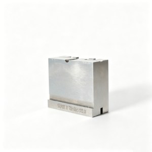
Representative Precision Components for Hardness-Test Planning





Related Precision Components and Drawing-Based Quotation




Why Build Hardness Testing Into the Plan?
Early hardness-test planning aligns material condition, process sequence, protected features and inspection evidence before production commitments.
Select the Right Method
Match the test method, scale, load and test location to the material condition, part geometry and specified acceptance requirement.
Sequence Heat Treatment
Define hardness testing around heat treatment, stress relief and finishing so results represent the required material condition.
Protect Critical Dimensions
Plan test coupons or designated locations to avoid affecting functional datums, sealing surfaces, thin walls and precision-fit features.
Align Inspection Evidence
Specify the hardness scale, sampling basis, reporting format and traceability needed for drawing review, acceptance and final documentation.
Review Process Risks Early
Identify grinding allowance, EDM strategy, coating condition and machining access before hardness requirements create avoidable rework.
Precision Part and Tooling Families
Drawing-driven process routes for hardness-sensitive components, custom parts, and tooling work requiring disciplined DFM, machining, inspection, and revision control.

CNC Machining Services
Precision CNC machining services for drawing-based parts requiring defined datums, critical dimensions, material requirements, and inspection planning. Process selection may combine milling, turning, EDM, grinding, and fitting according to geometry, hardness condition, quantity, and documented quality expectations.
Upload a Drawing
CNC Milling
Custom CNC milling services for prismatic components, inserts, plates, pockets, and complex machined features. Drawing review addresses tool access, corner radii, datum relationships, stock allowance, surface requirements, and whether subsequent EDM, grinding, or heat treatment affects the route.
Upload a Drawing
CNC Turning
Precision CNC turning services for shafts, pins, bushings, sleeves, and rotational components. Requirements are reviewed for concentricity, runout, thread details, material condition, turning access, and inspection method before committing to a manufacturing and quality-control plan.
Upload a Drawing
5-Axis Machining
5-axis CNC machining supports complex surfaces and multi-face features where part orientation, tool reach, and reduced setups affect accuracy and lead-time planning. SUUXIANG reviews fixture strategy, tool access, datum transfer, finishing allowances, and downstream inspection needs from the drawing.
Upload a Drawing
Swiss & Micro Machining
Swiss machining and micro machining support small-diameter pins, shafts, sleeves, and connector-related components with demanding feature relationships. Feasibility depends on material, diameter, length-to-diameter ratio, tolerances, surface requirements, cutoff strategy, and suitable measurement methods.
Upload a Drawing
Wire & Sinker EDM
Wire EDM and sinker EDM services support hardened features, sharp internal geometry, narrow slots, detailed cavities, and shapes limited by conventional tool access. Planning considers wire path or electrode strategy, flushing, finish requirements, EDM allowance, recast-layer considerations, and later fitting or polishing.
Upload a Drawing
Precision Grinding
Precision surface and profile grinding supports controlled flatness, parallelism, profile geometry, and final stock removal on hardened or heat-treated parts. The process route should define grinding allowance, datum condition, wheel access, thermal effects, surface requirements, and the inspection plan.
Upload a Drawing
Mold Core & Cavity Inserts
Precision mold core and cavity inserts are produced from customer drawings and verified material specifications. Reviews focus on molding surfaces, shutoffs, cooling or venting interfaces, datum strategy, heat-treatment sequence, EDM and grinding allowances, fitting relationships, and dimensional inspection requirements.
Upload a Drawing
Ejector & Ejection Components
Ejector pins, sleeves, and ejection components are evaluated for fit, guidance, stroke-related interfaces, material and hardness requirements, and surface condition. The manufacturing route considers concentric features, working clearances, heat treatment, grinding stock, and measurement of critical mating dimensions.
Upload a Drawing
Core Pins, Guide & Locating Components
Core pins, guide pins, and locating components require controlled relationships with mating parts, not isolated dimensions alone. Drawing review addresses datum definition, fit class, straightness, concentricity, engagement geometry, material condition, heat treatment, grinding needs, and inspection evidence.
Upload a Drawing
Slides, Lifters, Gates & Mold Accessories
Mold slides, lifters, gates, and accessories are handled as configurable drawing-based components rather than catalog assumptions. Reviews examine travel and mating interfaces, wear surfaces, tool access, EDM features, heat-treatment order, grinding stock, assembly fitting needs, and critical dimensional relationships.
Upload a Drawing
Connector Mold Components
Precision connector mold components support tooling features where fine pitch, insert alignment, cavities, cores, and mating geometry require disciplined control. SUUXIANG reviews material, micro-feature accessibility, EDM or grinding strategy, critical dimensions, inspection method, and revision-controlled documentation before production.
Upload a Drawing
Stamping Die Components
Precision stamping die components can include punches, dies, inserts, guide elements, and custom wear components manufactured to supplied drawings. Process planning considers material and hardness, cutting-edge geometry, clearance relationships, wire EDM needs, grinding sequence, surface condition, and dimensional verification.
Upload a Drawing
Injection, MIM, CIM & Overmolding Tooling
Injection, MIM, CIM, and overmolding tooling work is evaluated within verified production scope. Drawings should clarify parting and shutoff geometry, molding interfaces, material and heat-treatment needs, machining access, EDM requirements, fitting relationships, and inspection expectations for each tooling component.
Upload a Drawing
Machining Materials
CNC machining materials are selected against the drawing, application, hardness condition, corrosion exposure, wear demands, and downstream treatment requirements. Buyers should specify grade, acceptable substitute policy, material documentation needs, heat-treatment condition, and any constraints affecting machining or inspection.
Upload a Drawing
Surface Finishes & Heat Treatment
Surface finishing and heat treatment requirements must be tied to functional surfaces, dimensions, and order sequence. SUUXIANG reviews finish type, hardness target where specified, masking or cosmetic constraints, machining and grinding allowances, distortion risk, and final inspection requirements before production planning.
Upload a Drawing
Quality, Metrology & Documentation
Precision inspection, metrology, and quality documentation are planned around critical dimensions, datums, tolerances, and customer reporting requirements. RFQs should identify required reports, sampling expectations, measurement methods, revision status, material evidence, and any traceability needed for the delivered order.
Upload a Drawing
Prototyping & Low-Volume Production
Rapid prototyping and low-volume manufacturing support drawing-driven validation, engineering changes, bridge quantities, and controlled component releases. A useful RFQ provides the drawing and model, quantity, material, critical dimensions, surface and heat-treatment requirements, inspection needs, target date, and revision information.
Upload a DrawingMaterials for Hardness Testing Planning

Tool Steels
Commonly considered for mold cores, cavity inserts, punches and die components where heat treatment, grinding stock and wear exposure must be reviewed together. Hardness-test method and test location should follow the drawing and part geometry.

Stainless Steels
Considered for corrosion-sensitive precision parts, connector tooling and custom components. Material condition, heat treatment and surface requirements can influence machining access and hardness-test selection, especially where small features or finished surfaces limit test locations.

Alloy Steels
Often reviewed for pins, shafts, guide elements and structural tooling parts requiring a defined balance of strength, toughness and machinability. The drawing should identify critical dimensions, heat-treatment condition and any required hardness range before production planning.

Copper Alloys
Used where electrical or thermal performance is relevant, including selected connector and tooling applications. Alloy grade, work-hardening behavior and surface condition affect machining strategy; the specified hardness scale and allowable test impression require early review.

Aluminum Alloys
Suitable for selected fixtures, prototype parts and lightweight production components. Temper condition, section thickness and surface treatment should be confirmed when hardness testing is requested, because the test method and load must suit the finished part.
Hardness Testing Process Planning for Precision Parts


Wire EDM
Wire EDM creates precise profiles, slots, and internal details where conventional tool access is limited. The wire path, start-hole strategy, and finish-pass requirements are reviewed against hardness condition, tolerances, and surface expectations.

Sinker EDM
Sinker EDM supports cavities, deep features, and complex forms requiring electrode access. Electrode strategy, sparking allowance, and subsequent finishing needs are planned so hardness-sensitive surfaces can be evaluated within the agreed inspection approach.

Precision Grinding
Precision grinding brings hardened or heat-treated features toward their required size, flatness, or surface condition. Grinding stock, datum references, and sequence are reviewed to reduce the risk of removing too much material after treatment.

Heat Treatment
Heat-treatment coordination connects material specification, target condition, machining allowance, and distortion risk. SUUXIANG reviews when treatment occurs in the route and what dimensional or hardness evidence must be supplied for the order.

Fitting Inspection
Fitting and inspection verify functional relationships between mating features after the planned process route. Measurement methods, critical dimensions, hardness-report expectations, and revision status should be defined from the drawing before final acceptance.
Hardness Testing Component Features and Finishing Options

Threaded Features
Internal or external threads can be planned around datum surfaces, tool access and post-treatment sequence. Share thread callouts, engagement requirements and gauging expectations so machining and hardness testing remain coordinated.

Locating Elements
Dowel holes, guide features, keyways and mating references help establish repeatable assembly location. Define functional datums, fit requirements and the mating-part context for a practical machining, grinding and inspection strategy.

Surface Treatments
Coatings, heat treatment and surface finishes must be reviewed against critical dimensions, masking needs and final application. Identify the specified treatment, target condition and measurement points before production planning begins.

Part Identification
Laser marks, revision identifiers and traceability labels can support receiving, assembly and quality records. Provide marking content, location restrictions and legibility requirements so identification does not interfere with functional surfaces.

Protective Packaging
Custom protective packaging can help prevent contact damage, corrosion exposure or mix-ups during shipment. Share handling risks, part geometry, quantity per pack and delivery requirements for an appropriate documented packing approach.
Hardness Testing Starts With Drawing Control
SUUXIANG is the public-facing brand of Dongguan SuuXiang Precision Mold Co., Ltd., established in 2010 in Chang’an Town, Dongguan, Guangdong, China. We help international engineering and sourcing teams turn drawings, models, material specifications, and quality requirements into inspected precision parts and tooling components.
Our work combines CNC milling and turning, multi-axis machining, EDM, precision grinding, fitting, and inspection for custom CNC parts, precision mold components, connector tooling, and stamping-die components. Hardness testing is planned in context with material, heat-treatment sequence, critical dimensions, surface requirements, and the inspection evidence required for the order.
What differentiates SUUXIANG is a drawing-driven engineering workflow. Before quotation or production commitments, we review DFM, datums, machining access, EDM or grinding allowances, inspection methods, revisions, and delivery priorities. This helps teams identify manufacturability risks early and align the production route with the part’s functional requirements.

Hardness Testing Workflow: From Drawing Review to Inspection Evidence
Review Critical Dimensions First
Before quotation, SUUXIANG reviews the drawing, model, material condition and application context to identify dimensions affected by hardness requirements. The discussion establishes datums, tolerance priorities, surface requirements and the evidence needed before a process route is committed.
- Identify critical-to-quality features and functional interfaces
- Confirm material, heat-treatment and surface-condition requirements
- Flag tolerance-stack and datum dependencies early
- Define revision-controlled inputs for quotation

Plan the Manufacturing Sequence
Hardness testing is most useful when it is considered with the manufacturing sequence, not added after machining. SUUXIANG evaluates machining allowance, heat-treatment timing, tool access and distortion risk so CNC, EDM and grinding steps support the agreed part condition.
- Reserve stock where grinding follows heat treatment
- Assess distortion-sensitive features and sequence dependencies
- Match CNC, EDM and grinding to feature geometry
- Review access for electrodes, wire paths and inspection points

Align EDM and Grinding Strategy
For hardened mold and connector-tooling components, EDM and grinding decisions can affect final dimensions, surfaces and inspection access. SUUXIANG plans these operations around the drawing’s critical features, clarifying where finishing allowance, edge condition or localized measurement needs attention.
- Set grinding stock against final dimensional targets
- Evaluate EDM geometry, electrode strategy and wire path
- Protect datum relationships through finishing operations
- Discuss surface and edge requirements before release

Document Agreed Inspection Evidence
Inspection documentation should reflect the order, revision and agreed critical dimensions. SUUXIANG aligns the inspection plan with the required hardness testing method, measurement locations and reporting expectations, then keeps revision and delivery information visible through project coordination.
- Agree the hardness scale, locations and acceptance criteria
- Link reports to the applicable drawing revision
- Record critical-dimension inspection requirements
- Submit RFQs with reporting and delivery expectations

Hardness Testing Planning for Drawing-Based Precision Work
Compare disciplined drawing review and inspection planning with quote-led sourcing workflows.
← Swipe left or right to view →
Hardness Testing Production and Inspection Process
A drawing-led workflow that aligns material condition, process sequence, inspection evidence, and delivery requirements before production proceeds.
Review RFQ Package
We review drawings, models, quantities, material requirements, critical dimensions, surface priorities, hardness testing needs, inspection requests, and target delivery dates.
Plan Process Route
The team confirms DFM points, datum strategy, heat-treatment sequence, machining access, EDM or grinding allowances, and an inspection plan appropriate to the order.
Machine Critical Features
CNC machining, multi-axis work, turning, wire EDM, sinker EDM, and grinding are sequenced around geometry, tolerance stack, material condition, and tool access.
Verify Material Condition
Where specified and supported by the project plan, hardness testing is coordinated with the required material condition, test location, method, acceptance criteria, and records.
Inspect and Release Parts
Final inspection follows the agreed plan, documenting critical dimensions and applicable hardness results before release, packing, revision identification, and delivery coordination.
Start Your Hardness Testing Project
Move from technical requirements to controlled production through a documented review, approval, and inspection path.
Upload Your RFQ Package
Send the 2D drawing, 3D model when available, material, heat-treatment, quantity, critical dimensions, inspection requirements, application context, and target delivery date.
Confirm DFM and Quote
Review machining access, datum strategy, EDM or grinding needs, test locations, acceptance criteria, revision status, and the proposed process route before quotation approval.
Approve First-Article Evidence
Where the project requires it, assess agreed sample or first-article results against the drawing, hardness testing plan, dimensional priorities, and documented inspection method.
Release Controlled Production
Authorize production after requirements are aligned; SUUXIANG maintains revision visibility, applies the agreed inspection plan, and coordinates final documentation with delivery.
Hardness Testing Certifications and Quality Documentation
Hardness Testing Customer Outcomes
Verified client testimonial pending approval. This space will feature a documented engineering, quality, or delivery outcome only after the customer approves the wording, attribution, and supporting project evidence.
Verified client testimonial pending approval. SUUXIANG publishes customer outcomes only when the quoted result, inspection context, and customer identity or anonymity preference have been reviewed and authorized.
Verified client testimonial pending approval. A future case may describe drawing-review, hardness testing, dimensional inspection, or delivery coordination results when verified records and customer permission are available.
Customer Outcomes: Documentation Available Upon Approval
Plan the method, sequence, evidence, and commercial requirements around the actual drawing and application.
Which hardness testing method should I specify for a precision part?
Can hardness testing be performed after heat treatment and grinding?
What information is needed to plan hardness testing for a custom CNC part?
How accurate is hardness testing on small, thin, or irregular parts?
Can hardness testing verify that a part meets its required material condition?
What hardness testing report can I request with my order?
Is there a minimum order quantity for hardness-controlled components?
How do lead time, shipping, payment, and IP protection work for a drawing-based order?
The Complete Buyer’s Guide to hardness testing
Use this decision framework to select suitable methods, specify acceptance criteria, evaluate precision-part suppliers, and avoid costly sampling, documentation, and hardness-scale mistakes before production.
1. What Is hardness testing?
1. Hardness testing measures a material’s resistance to localized permanent deformation, typically by a controlled indenter. The resulting value describes the tested condition at that location; it is not a direct measure of tensile strength, ductility, or in-service wear life.
2. Buyers use hardness results to check whether supplied stock and heat-treated precision parts appear consistent with the specified material condition. A conforming value alone does not prove complete heat-treatment quality, because case depth, microstructure, residual stress, and dimensional change may require separate verification.
3. Every reportable result needs four identifiers: hardness value, scale or method, applied test force, and exact test location. For example, 800 HV10 on a specified core-pin cross-section is interpretable; ‘hardness 800’ is not, because the scale, load, and sampling position are missing.
4. For drawing-based mold, connector, and die components, agree the test point before machining and heat treatment begin. Location matters because surfaces, thin sections, ground areas, and local heat effects can produce readings that do not represent the functional zone.
2. Evolution of hardness testing
1812 brought Friedrich Mohs’s scratch-comparison scale, a useful relative ranking but one too operator-dependent for release decisions on precision parts. Its limitation made controlled indenter geometry, force, dwell, and result reporting essential to repeatable hardness testing.
1900 saw Johan August Brinell formalize ball indentation; Rockwell and Vickers later made depth- and optical-indent methods practical across production and laboratory work. These methods turned hardness from a comparative observation into a specification that could be tied to a defined scale, load, indenter, test location, and documented result.
Modern digital systems can capture test parameters and results, while microhardness methods use small loads for thin sections, surface layers, coatings, and localized features. For complex mold and connector components, supplier-quality expectations now include the applicable standard, calibrated equipment, prepared test surface, traceable record, and a test method suited to the available section thickness and geometry. Source: https://www.zwickroell.com/industries/materials-testing/hardness-testing
3. Types of hardness testing
Six methods answer different acceptance questions because indenter shape, load, and indentation depth change what the result represents. Specify the method with the material condition and test location.
| Method | Principle | Best Fit | Notation | Limitation | Procurement Question |
|---|---|---|---|---|---|
| Brinell | Carbide ball | Coarse stock | HBW | Large indent | Is bulk uniform? |
| Rockwell | Depth, cone or ball | Hardened parts | HRC/HRB | Geometry-sensitive | Does heat treatment comply? |
| Vickers | Diamond diagonals | Metals, sections | HV | Needs polished surface | What is local hardness? |
| Knoop | Elongated diamond | Coatings, thin layers | HK | Optical measurement | Is layer hardness verified? |
| Shore | Durometer depth | Plastics, elastomers | Shore A/D | Not for metals | Is polymer grade controlled? |
| Rebound | Impact energy | Large installed parts | HL | Correlation required | Is portable screening acceptable? |
Macro Metal Methods
Brinell uses a carbide ball and a broad impression for coarse or inhomogeneous stock; report HBW. Ask whether bulk material is uniform, noting the large indent limits finished small parts.
Rockwell measures penetration depth using a diamond cone or ball; report the scale, such as HRC. Ask whether a hardened mold component meets its specified condition; thin sections and curved surfaces need suitability review.
Micro And Polymer Methods
Vickers uses a diamond pyramid and optical diagonals; report HV with test force. It suits machined sections and hardness traverses, but preparation and optical reading matter.
Knoop uses an elongated diamond; report HK for coatings, ceramics, and thin layers. Shore uses a durometer penetration scale, such as Shore A or D, for plastics and elastomers.
Selection Checklist
Portable rebound testers infer hardness from impact response and are useful for large installed metal parts; ask whether correlation and surface condition are accepted.
Before RFQ release, identify part condition, accessible test face, thickness, allowable indent, required notation, and report format.
- Machined parts: Rockwell or Vickers
- Mold components: specified HRC or HV
- Coatings and thin sections: Knoop or micro-Vickers
- Plastics: Shore A or Shore D
4. Hardness testing by material and part geometry
Method selection starts with the actual alloy, heat-treatment condition, section thickness, and accessible test face. A hardness number is meaningful only when its scale, load, preparation, and location are recorded.
| Material Or Condition | Suitable Method | Preparation And Interpretation |
|---|---|---|
| Bulk steel or tool steel | Rockwell or Vickers | Flat supported face; record scale and heat-treatment state |
| Aluminum or copper alloy | Brinell or low-load Vickers | Avoid thin sections; compare like tempers |
| Thin coating or ceramic | Knoop or micro-Vickers | Polished cross-section; isolate layer response |
| Plastic | Shore durometer | Condition specimen; report temperature and geometry |
| Curved, thin, plated, or welded part | Coupon or microhardness map | Use representative process and defined test locations |
Match Material To Method
Steel, tool steel, and stainless commonly suit Rockwell or Vickers on a flat, supported surface. Aluminum and copper alloys often need a ball method or lower-load Vickers to avoid an oversized indent.
Plastics require Shore durometry; brittle ceramics and thin coatings favor low-load Knoop or Vickers. Method ranges and load categories are summarized by ZwickRoell: https://www.zwickroell.com/industries/materials-testing/hardness-testing
Geometry Changes The Result
Thin walls, small radii, and curved surfaces can distort an indent or lack support beneath it. Machine or prepare a flat test pad only if the drawing permits and its removal does not affect function.
Plated areas require a load shallow enough to characterize the coating rather than the substrate. When that separation is not feasible, test a representative plated coupon made with the same process.
Map Zones Separately
Case-hardened layers need a cross-section microhardness traverse from surface into core; a macro reading can mask the gradient. Welded zones need separate readings in weld metal, heat-affected zone, and parent metal.
Each report should identify location, preparation, scale, load, dwell, and any coupon relationship. Vickers mapping is commonly used across weld regions: https://www.cwbgroup.org/resources/articles/hardness-testing
5. Specifying hardness testing on engineering drawings
A drawing note such as ‘58–62 HRC’ is incomplete unless it defines the method, condition, and acceptance evidence. Tie hardness testing to the feature’s wear, mating, or distortion risk—not to a legacy callout.
Define The Test Method
ISO 6508-1:2023 or the applicable customer standard should be named with its revision, scale, range, indenter, and test force. Write the reported format explicitly, such as 58–62 HRC, rather than converting values from another scale without an approved correlation.
Locate And Time Measurements
Three or more defined locations can be appropriate when hardness variation affects a core pin, cavity insert, or heat-treated contact surface. State the surface preparation, minimum spacing from edges or prior indents, and whether readings occur before or after coating, grinding, EDM, stress relief, or final heat treatment.
Set Sampling And Records
One purchase-order note should define the lot, sample quantity, retest disposition, and report fields before production starts. Require part number, revision, material and treatment condition, tester identification, method, load, locations, individual results, acceptance range, date, and inspector traceability.
6. Quality elements behind reliable results
Two controls determine whether a hardness result is credible: the test method is executed consistently, and its record remains tied to the actual part, revision, and heat-treatment condition.
Equipment And Reference Checks
1 calibrated tester, correct indenter, and verified reference block should be confirmed before the planned test sequence.
1 qualified operator should document the selected scale, load, dwell, reference-block result, and any setup exception.
Specimen Preparation And Location
2 stable support conditions matter: insufficient section thickness, curved contact, vibration, or loose fixturing can distort an indentation result.
1 clean, prepared surface and repeatable location plan reduce variation from scale, coatings, roughness, edge effects, and nearby indents. https://www.struers.com/en/knowledge/hardness-testing
Traceable Inspection Records
3 inspection stages should connect: first-article results confirm the agreed setup, in-process checks monitor the route, and final records verify the released lot.
1 traceability chain should link part number, drawing revision, material or heat-treatment batch, measurement locations, method, and acceptance decision to the shipment.
7. How to choose a hardness testing supplier
A supplier choice should begin with the drawing, not a claimed tester list. For hardness testing, match the specified scale, test location, part geometry, heat-treatment condition, and acceptance rule before quotation.
Match Method To Geometry
Rockwell may be unsuitable where a small, thin, curved, or hardened feature cannot support the required indentation. Request a proposed method, load, indenter, fixture, test locations, and any sectioning or sacrificial-sample plan.
Vickers or Knoop may be considered for small areas or thin layers, but the supplier should show why the method fits the drawing.
Request Objective Evidence
ISO or ASTM familiarity is a claim; current calibration records, machine identification, indenter verification, and operator procedure are evidence. Ask for a redacted sample report showing scale, force, dwell, readings, location, acceptance limits, date, and traceable part revision.
Material certificates and heat-treatment records should remain linked to the tested lot, not merely the purchase order.
Gate Each Program Phase
Before RFQ, ask which method fits the geometry and whether testing marks affect function. At first article, confirm the inspection plan, sample handling, report format, and response path for an out-of-specification result.
Before production release, require revision-controlled acceptance criteria, lot traceability, and a named communication cadence across time zones.
- RFQ: method, access, sampling, turnaround
- First article: locations, readings, report review
- Release: lot linkage, corrective action, escalation
8. Common hardness testing mistakes buyers make
Two recurring failures are incomplete specifications and unrepresentative readings. Both can turn a conforming heat-treatment result into a fit, wear, brittleness, or acceptance dispute.
Define The Test Completely
One hardness number is not a complete requirement: HRC, HV, and HBW are method-specific, and conversion tables are approximate. State the scale, test force, dwell, standard, test location, acceptance range, and any approved conversion.
Control Surface And Geometry
A rough, curved, decarburized, or poorly supported surface can distort an indentation. Require a prepared test area and a method suitable for section thickness; excessive load on thin parts can sample through the intended hardened zone.
Sample Variation Deliberately
Three readings averaged together can hide an edge-soft zone, local overheating, or brittle hard spot. Define the number and distribution of readings, keep indents clear of edges, and review individual values against the drawing requirement.
One hardness result does not prove tensile strength, ductility, toughness, microstructure, or coating adhesion. Add the relevant material certificate, metallographic check, or mechanical test when application risk demands it.
9. Launching a hardness-controlled part program
1 approved functional requirement should define the hardness range, test scale, location, and functional risk before material selection. Design, sourcing, manufacturing, heat treatment, and quality should jointly approve one inspection plan.
Prototype And Drawing Release
1 prototype lot should verify the selected material, heat-treatment route, test access, and any post-treatment grinding allowance.
2 released drawings should identify datums, critical features, hardness-test locations, acceptance limits, and revision level before a purchase order is placed.
First Article And Sampling
1 first-article inspection should compare actual hardness results and dimensions with the approved drawing and inspection plan.
3 production stages need defined sampling frequency, lot traceability, report format, and escalation criteria; do not substitute an unspecified conversion for the required scale.
Documents Before Production
1 controlled document package prevents a supplier from manufacturing to an obsolete requirement. Quality should confirm the package matches the order before release.
- 2D drawing and 3D model
- Material and heat-treatment specification
- Approved inspection plan and report format
- First-article, sampling, and traceability requirements
- Revision, nonconformance, and change-control process
10. Hardness testing cost and lead-time factors
2 commercial inputs—an actual drawing and the hardness specification—are the starting point for a defensible quote. Quantity, test locations, acceptance criteria, and the agreed inspection plan determine whether setup or per-part work dominates.
1 added requirement can change both schedule and cost: surface preparation, difficult access, micro-load work, serialized reporting, or external laboratory confirmation. SUUXIANG should quote these items against the current lot and revision rather than publish fixed prices.
| Cost and schedule driver | Setup effort | Per-part inspection effort | Lead-time impact |
|---|---|---|---|
| Rockwell on accessible, prepared faces | Low | Low | Low |
| Vickers or microhardness; thin zones | Medium | Medium–high | Medium |
| Complex geometry; fixture or sectioning needed | High | High | Medium–high |
| Larger lot with defined sampling plan | Medium | Lower per part | Low–medium |
| Full report, traceability, or external laboratory | Medium | High | High |
The Complete Buyer’s Guide to Hardness Testing
Submit drawings, material and heat-treatment requirements, quantity, critical dimensions, inspection expectations, and target delivery date for a technical review.