
Part Traceability for Precision CNC and Tooling Parts
Move from drawing review to inspected delivery with part traceability, revision control, and documentation aligned to your custom component requirements.
Representative Precision Components for Traceability Review





Custom Component Families and Quotation


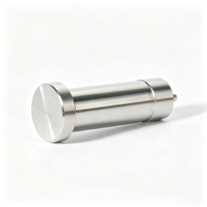


Part Traceability for Critical Requirements
Keep drawing intent, revision status, inspection priorities, and delivery information visible throughout a drawing-driven manufacturing project.
Drawing Review
Align drawings, models, datums, material requirements, and critical dimensions before quotation so the manufacturing route reflects the intended part function.
Revision Visibility
Confirm the applicable drawing revision and record key project updates to reduce avoidable confusion between engineering, purchasing, production, and inspection.
Critical Dimension Focus
Identify critical-to-quality dimensions, surface requirements, and datum relationships early so machining, EDM, grinding, and inspection planning stay aligned.
Process Route Planning
Review machining access, electrode strategy, wire paths, heat-treatment sequence, and grinding stock before production commitments are made.
Inspection Alignment
Match final documentation to the order and verified inspection plan, with measurement priorities defined around the part’s specified requirements.
Delivery Coordination
Keep revision and delivery information visible during project coordination, helping teams prepare for incoming inspection, assembly, and next-stage work.
Custom Parts and Tooling We Support
Drawing-driven process routes for precision components, tooling families, and controlled prototype or low-volume production.

CNC Machining Services
Precision CNC machining services for drawing-based parts requiring coordinated milling, turning, EDM, grinding, fitting, and inspection. Review begins with material, critical dimensions, datums, surface requirements, quantity, and delivery needs before a process route is proposed.
Upload a Drawing
CNC Milling
Custom CNC milling services for prismatic parts, mold plates, inserts, and features where tool access, clamping, datum transfer, and machining allowance affect the outcome. Share the 2D drawing, 3D model, critical dimensions, and surface priorities for DFM review.
Upload a Drawing
CNC Turning
Precision CNC turning services for rotational parts such as pins, sleeves, bushings, shafts, and locating features. Diameter control, concentricity, runout, thread requirements, material condition, and downstream grinding or heat treatment should be defined in the RFQ.
Upload a Drawing
5-Axis Machining
5-axis CNC machining supports complex contours, angled features, multi-face parts, and geometries that benefit from fewer setups. Feasibility depends on workholding, cutter reach, collision clearance, datum strategy, material condition, and the inspection approach for critical surfaces.
Upload a Drawing
Swiss & Micro Machining
Swiss machining and micro machining support small, slender, and detailed components where part support, tool geometry, burr control, and measurement strategy matter. Provide dimensions, tolerances, material, quantity, and mating-function context so manufacturability can be assessed responsibly.
Upload a Drawing
Wire & Sinker EDM
Wire EDM and sinker EDM services address hardened materials, narrow slots, sharp internal geometry, deep features, and details with limited milling access. Electrode design, wire path, flushing, recast-layer considerations, finish requirements, and final inspection must align with the drawing.
Upload a Drawing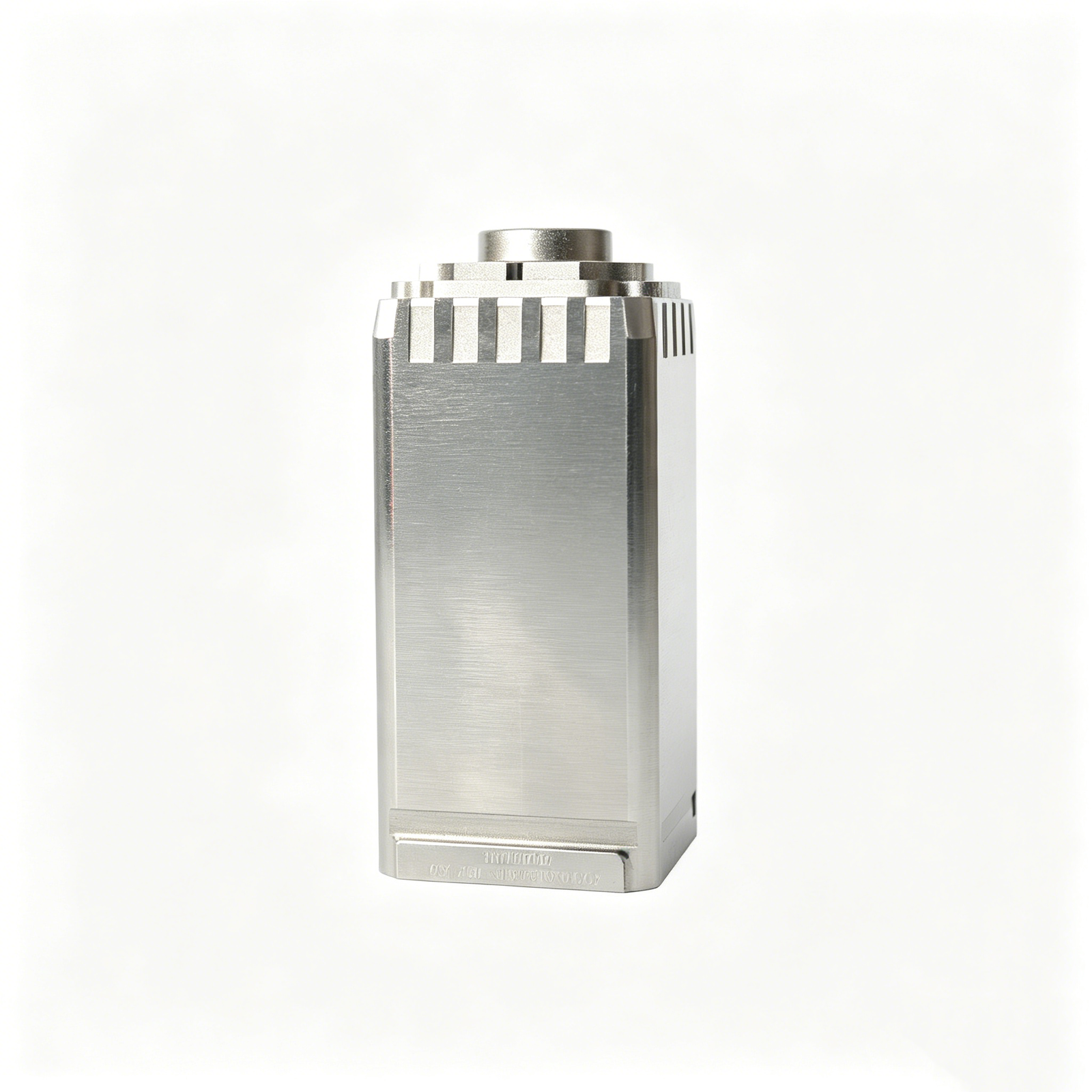
Precision Grinding
Precision surface and profile grinding supports controlled flatness, parallelism, profiles, and finished dimensions after machining or heat treatment. Grinding stock, datum surfaces, material hardness, distortion risk, surface requirements, and inspection points should be agreed before production.
Upload a Drawing
Mold Core & Cavity Inserts
Precision mold core and cavity inserts are manufactured from customer drawings and specifications, with machining, EDM, grinding, fitting, and inspection planned around critical molding surfaces. Material, heat treatment, shutoff conditions, cooling details, and mating interfaces require early review.
Upload a Drawing
Ejector & Ejection Components
Ejector pins, sleeves, and ejection components require attention to fit, clearance, wear surfaces, hardness condition, and movement within the mold assembly. Drawings should identify critical diameters, guiding features, surface requirements, and associated mating components.
Upload a Drawing
Core Pins, Guide & Locating Components
Core pins, guide pins, and locating components are produced around functional alignment and repeatable assembly. Datum relationships, mating bores, fits, concentricity, material and heat-treatment requirements, and inspection methods should be stated clearly before quotation.
Upload a Drawing
Slides, Lifters, Gates & Mold Accessories
Mold slides, lifters, gates, and accessories are configurable tooling components rather than assumed stock items. Their manufacturability depends on travel geometry, shutoff surfaces, wear interfaces, cooling or venting details, material condition, and the defined assembly relationship.
Upload a Drawing
Connector Mold Components
Precision connector mold components support fine-pitch, high-density, and functional connector tooling requirements. Pin geometry, cavity alignment, EDM strategy, polishing or surface expectations, material selection, and dimensional inspection must be reviewed against the mating-component context.
Upload a Drawing
Stamping Die Components
Precision stamping die components are made for drawing-defined punch, die, guide, locating, and wear-part applications. Material, hardness, edge condition, clearance relationships, grinding requirements, and assembly datums should be established before the manufacturing route is confirmed.
Upload a Drawing
Injection, MIM, CIM & Overmolding Tooling
Injection mold components and tooling for MIM, CIM, and overmolding are evaluated within verified production scope. A complete review considers material-flow surfaces, shrinkage assumptions, insert interfaces, gate and vent details, heat treatment, finishing, assembly, and inspection expectations.
Upload a Drawing
Machining Materials
CNC machining materials are selected against functional requirements rather than a generic list. Identify the specified grade, material condition, traceability needs, heat-treatment state, corrosion or wear exposure, and any substitution restrictions so the proposed route remains aligned with the drawing.
Upload a Drawing
Surface Finishes & Heat Treatment
Surface finishing and heat treatment are planned as part of dimensional control, not treated as an afterthought. Specify finish type, roughness, coating requirements, hardness or case-depth targets, masking needs, distortion sensitivity, and post-treatment grinding or inspection expectations.
Upload a Drawing
Quality, Metrology & Documentation
Precision inspection, metrology, and quality documentation are defined around the order’s critical-to-quality features. Agree on drawing revision, datums, sampling or full-inspection expectations, measurement method, report format, material evidence, and traceability requirements before production begins.
Upload a Drawing
Prototyping & Low-Volume Production
Rapid prototyping and low-volume manufacturing support design validation, tooling trials, revisions, and controlled bridge quantities. Provide the current drawing revision, quantity range, material and finish requirements, critical features, inspection needs, and target date for a practical review.
Upload a DrawingMaterials for Part Traceability Review

Tool Steels
Used for mold cores, cavity inserts, and wear-sensitive tooling. Grade, hardness target, machining allowance, and heat-treatment sequence affect EDM, grinding, inspection planning, and part traceability records.

Stainless Steels
Selected for corrosion resistance, cleanability, or moisture-exposed applications. Alloy grade, condition, surface requirement, and machining behavior should be defined so material identification and final inspection align with the drawing.

Carbon Alloy Steels
A practical option for structural components, guides, and custom machined parts. Heat treatment can change distortion risk and grinding stock, so material certificates and critical-dimension requirements need early review.

Aluminum Alloys
Often specified for lightweight fixtures, prototypes, and non-wear tooling elements. Alloy temper influences machinability, stability, and surface finishing; confirm the required grade and inspection priorities before quotation.

Copper Alloys
Applied where electrical conductivity or thermal transfer matters, including selected connector and tooling applications. Softer machining characteristics and finish sensitivity require clear datum, surface, and handling requirements.
Machining and Inspection Processes Supporting Part Traceability


Wire EDM
Wire EDM creates detailed profiles, narrow slots, and hardened-part features where conventional tool access is limited. The planned wire path, datum references, and inspection points help connect the finished feature to its documented process route.

Sinker EDM
Sinker EDM supports internal forms, sharp corners, and complex cavity features using an electrode strategy matched to the drawing. Electrode details, machining sequence, and required surface condition should be reviewed before work begins.

Precision Grinding
Precision grinding refines critical faces, diameters, and mating surfaces after the appropriate machining or heat-treatment stage. Grinding stock, datum control, and measurement method are defined against the part’s functional requirements and inspection plan.

Fitting Assembly
Fitting verifies how related mold, connector-tooling, or die components engage in the intended assembly. Mating conditions, adjustment needs, and revision status should be communicated so observed results can be evaluated against the approved documentation.

Final Inspection
Final inspection checks the agreed critical dimensions and reporting requirements against the current drawing revision. Part traceability is supported when inspection results, order information, and any requested documentation are matched to the verified production plan.
Part Traceability Features and Identification Options

Marking Areas
Reserve a noncritical, accessible surface for a part number, revision, lot code, or customer-specified identifier. Review mark location, method, legibility, and any cosmetic or functional restrictions with the drawing.

Datum Locating Features
Pins, holes, flats, and reference faces can establish repeatable orientation for machining, inspection, assembly, and identification. Specify functional datums and critical relationships so fixture strategy and measurement methods can be reviewed early.

Guide Elements
Guide pins, bushes, locating blocks, and related alignment features support controlled assembly of mold, connector-tooling, and die components. Their fit, hardness sequence, grinding stock, and mating relationships should be defined in the drawing package.

Part Identification Labels
When a permanent mark is unsuitable, a customer-specified label or tag can identify packaged components. Define required information, label position, material compatibility, and whether the identifier must correspond to inspection documentation or shipment records.

Packaging Identifiers
Carton, tray, bag, or container identifiers can distinguish part number, revision, quantity, lot, and handling requirements. Include packing format and any separation needs in the RFQ to support clear delivery coordination.
SUUXIANG’s Part Traceability Approach
Established in 2010 and based in Chang’an Town, Dongguan, Guangdong, China, SUUXIANG is the sole public-facing brand of Dongguan SuuXiang Precision Mold Co., Ltd. Founded by and legally represented by XiaoCheng Huang, we help global engineering, sourcing, and quality teams turn drawings into inspected CNC parts, precision mold components, connector tooling, and stamping-die components.
Our work begins with drawing interpretation and DFM review. Before quotation and production commitments, we clarify critical dimensions, datums, material and heat-treatment requirements, machining access, EDM or grinding needs, inspection expectations, and revision status. This establishes a practical basis for part traceability throughout the project.
SUUXIANG coordinates CNC milling and turning, multi-axis machining, EDM, grinding, fitting, and inspection as a controlled manufacturing workflow. We keep revision and delivery communication visible, then align final documentation with the order and verified inspection plan so teams can evaluate results against the requirements that governed production.

How Part Traceability Is Built Into Precision Manufacturing
Start With Drawing Review
Part traceability begins before quotation. SUUXIANG reviews the drawing, model, material, quantity, application, and quality expectations to identify critical dimensions, datum relationships, surface requirements, and manufacturability questions that need resolution before production planning.
- Confirm current drawing revision and applicable 3D model
- Identify critical-to-quality dimensions and functional datums
- Review machining access, tolerance stack, and surface callouts
- Record open DFM questions before process commitments

Plan the Process Route
A controlled route links the part requirement to the appropriate CNC machining, EDM, grinding, fitting, heat-treatment sequence, and inspection activities. The route should account for stock allowance, electrode or wire path, workholding, and the dimensional effects of each production stage.
- Define machining, EDM, grinding, and fitting sequence
- Set allowances for grinding and downstream finishing
- Review electrode strategy, wire access, and workholding needs
- Align heat-treatment timing with dimensional control

Keep Revisions Visible
Clear revision control supports reliable part traceability when drawings, specifications, or inspection requirements change. SUUXIANG coordinates the current production information against the order so teams can distinguish approved requirements, unresolved changes, and records relevant to the delivered parts.
- Match production records to the applicable order revision
- Clarify changes affecting dimensions, material, or finish
- Maintain visible communication on project updates
- Confirm documentation scope before final delivery

Document Inspection Evidence
Inspection planning should focus on the dimensions and features that affect fit, function, and acceptance. Final documentation is prepared to match the order and verified inspection plan, giving procurement and quality teams a practical basis to review measured results and part identification requirements.
- Select inspection methods for critical features
- Align report format with agreed quality requirements
- Verify final records against the applicable inspection plan
- Discuss identification and documentation needs with the RFQ

Part Traceability Through a Drawing-Driven Workflow
Compare the engineering evidence and project controls that support informed sourcing decisions before production begins.
← Swipe left or right to view →
Part Traceability Through the Production Workflow
From drawing review through shipment coordination, each project stage aligns manufacturing decisions, critical checks, and order-specific records.
RFQ and Drawing Review
Review drawings, models, material, quantity, critical dimensions, surface requirements, delivery target, and inspection needs before confirming a practical production route.
DFM and Process Planning
Confirm datum strategy, machining access, tolerance stack considerations, heat-treatment sequence, EDM requirements, grinding stock, and inspection methods against the current revision.
Machining and Revision Control
Produce components through the planned CNC milling, turning, multi-axis, Swiss, or micro-machining route while keeping approved drawing revisions visible.
EDM Grinding and Fitting
Apply wire EDM, sinker EDM, precision grinding, and fitting as required, with process choices linked to geometry, surfaces, allowances, and mating conditions.
Inspection and Record Review
Inspect defined critical features using the agreed method, review results against the order requirements, and assemble documentation matching the verified inspection plan.
Packing and Shipment Coordination
Confirm part identification, quantities, protective packing, and delivery details before shipment coordination, so supplied parts and accompanying records remain aligned.
Project Documentation Available by Agreed Scope
Move from controlled drawing review to inspected delivery with requirements, revisions, and documentation kept visible throughout the project.
Submit Drawings and Models
Provide the current 2D drawing, 3D model when available, quantity, application context, and target date so review begins from controlled project inputs.
Define Critical Requirements
Identify material, heat-treatment, surface, datum, tolerance, and inspection priorities. Note mating conditions or functional risks that affect machining access, EDM, grinding, and verification.
Review the Process Plan
Discuss DFM findings, critical dimensions, proposed process route, documentation needs, quotation assumptions, and any sampling requirements before production commitments are confirmed.
Approve the Released Revision
Confirm the quotation, drawing revision, agreed requirements, and any sample expectations before production proceeds under the approved project record.
Coordinate Delivery and Records
Confirm shipping timing and required final documents against the approved order and inspection plan, keeping revision status and delivery information visible through dispatch.
Customer Project Cases Await Authorization
Part Traceability: Customer Project Feedback and Outcomes
Verified customer case pending approval. This card will document the drawing revision, inspection-report scope, quantity, and measurable outcome once the customer has authorized publication of the project details.
Verified customer case pending approval. This card will describe how controlled revision handoffs, critical-dimension reporting, and documented issue resolution supported the customer’s specific production decision.
Verified customer case pending approval. This card will cite the approved scope, delivery context, inspection evidence, and a measurable result from a drawing-based CNC, mold-component, or tooling project.
The Complete Buyer’s Guide to Part Traceability
Practical guidance for preparing drawing-based RFQs, defining documentation needs, and aligning production records with your project requirements.
What information should I provide for part traceability on a CNC RFQ?
How is part traceability managed when a drawing revision changes?
Can I request inspection reports with my traceable parts?
What is the difference between lot traceability and individual part traceability?
Is there a minimum order quantity for CNC parts or mold components?
Can SUUXIANG provide samples or first-article parts before a larger order?
How should I specify lead time, shipping, and payment requirements?
How are drawings and IP handled during a part traceability project?
The Complete Buyer’s Guide to part traceability
A practical framework for specifying traceability on drawing-based CNC parts, evaluating supplier controls, comparing identification approaches, and avoiding documentation gaps that delay qualification, containment, and corrective action.
1. What Is part traceability?
One traceable CNC part is not merely a marked component; it is a component whose identity can be linked back to controlled records. For custom mold inserts, connector-tooling components, and low-volume machined parts, part traceability means recovering the relevant manufacturing history for an individual part or an identified lot.
Five record categories normally define that history: material source and condition, approved drawing revision, process route, inspection evidence, and shipment destination. The physical identifier may be a serial number, lot number, traveler reference, or packaging label, but the code has little value if records cannot be retrieved accurately.
A lot-based system can be appropriate when identical parts share material, process, and inspection controls; unit-level identification is useful where parts must be distinguished individually. Before release, the buyer’s practical question is whether a delivered part or lot can be connected to the correct revision, material evidence, process status, measured results, deviations or rework, and shipment record.
2. How part traceability Evolved
1950s-era production control commonly relied on paper travelers, route cards, and batch records that moved with a job. They could link a lot to material, operations, and inspection, but retrieval depended on legible entries and disciplined filing.
1970s barcode adoption made repeated identification and data capture faster at receiving, workstations, and shipment. Data Matrix codes later made durable, compact direct-part marking practical where geometry, surface condition, and downstream handling allowed it.
1990s–2000s supply chains became more global and products more complex, increasing the value of serialized histories and connected digital records. Regulated applications, recalls, and root-cause investigations raised expectations for faster scope definition, revision visibility, and evidence retrieval.
2026 requirements still vary by part risk, quantity, customer contract, and application. A low-volume mold insert may need controlled batch documentation, while a safety-critical assembly may require unit-level serialization and a linked record; the drawing and quality plan should define the appropriate level.
3. Types of part traceability
Six traceability levels differ in containment precision and administrative effort. Select the narrowest identifier scope that isolates a credible failure mode while matching the drawing, application, and inspection plan.
| Type | Identifier Scope | Linked Records | Nonconformance Resolution | Burden And Use |
|---|---|---|---|---|
| Lot | Material or receipt lot | Certificate, receipt | Contain lot | Low; stock material |
| Batch | Production run | Route, inspections | Contain run | Low-medium; repeat CNC |
| Serial/unit | Unique part | Measurements, rework | Isolate one unit | High; critical mating parts |
| Internal process | Traveler or work order | Stations, gauges | Locate failed step | Medium; multi-process inserts |
| Supplier-chain | Supplier-to-customer ID | Material, shipment | Trace upstream/downstream | High; outsourced processing |
| End-to-end | Persistent unit or lot ID | Source through delivery | Delimit affected population | Highest; regulated programs |
Lot And Batch Selection
One lot ID suits material or receiving control.
One batch ID suits a controlled production run.
Serial And Process Control
One serial ID can isolate a single nonconforming part.
One traveler ID links CNC, EDM, grinding, and inspection.
Supply-Chain Boundaries
Two-party supplier-chain records connect incoming and outgoing identifiers.
End-to-end records span source through delivery and require agreed data handoffs.
4. Materials, Processes, and Traceability Records
A traceable machining order begins before cutting: the material certificate, heat or lot number, and receiving check establish the first link between stock and finished part. That link must survive every approved process transfer.
| Evidence Point | Typical Record | Linking Risk |
|---|---|---|
| Incoming material | Certificate and heat or lot number | Mixed stock before segregation |
| Machining route | Traveler and revision record | Unlogged transfer or rework |
| External finish | Processor certificate | Lost order-to-lot linkage |
| Final release | Inspection report and shipment record | Records not matched to part lot |
Material Linkage And Review
Each received bar, plate, or blank should be matched to the supplier certificate, purchase record, material grade, and heat or lot identifier.
A drawing review should define whether lot-level linkage is sufficient or whether each finished component needs a unique serial record.
Route Records Across Operations
Each routing step should record the applicable revision, work order, operator or supplier transfer, and inspection result. CNC machining, EDM, grinding, heat treatment, plating, coating, welding, and fitting can each alter the evidence trail.
Outsourced processing needs its own certificate or report linked back to the same order and part lot.
Identification Limits And Retention
Tiny pins, polished faces, coated surfaces, and mixed material lots may prevent durable direct marking. In those cases, controlled containers, traveler records, and segregated batches preserve linkage without damaging function.
Final records should match the agreed inspection plan and identify any rework, split lot, or substituted operation before shipment.
5. Part Traceability Marking Options
One marking plan should identify the part, its revision or lot, and the record that explains it. For precision components, reserve a nonfunctional surface before selecting the method.
| Method | Permanence | Area And Finish Impact | Data And Reading | Post-Process Fit |
|---|---|---|---|---|
| Laser mark | High when validated | Small; may alter appearance | Text, barcode, QR, Data Matrix; scanner | Validate after finishing |
| Dot peen | High | Needs robust area; visible indent | Text or 2D code; scanner | Avoid functional surfaces |
| Ink mark | Low to medium | Small; minimal physical effect | Text or barcode; visual or scanner | Often applied last |
| Part or packaging label | Medium | No part impact; needs label area | High data; visual or scanner | Replace if process removes it |
| Traveler document | Not direct marking | No finish impact | Full route and inspection data | Maintained with the order |
Direct Marking Methods
Laser marks provide durable, high-contrast identification on many metals, but mark trials should confirm readability after heat treatment, coating, polishing, or passivation.
Dot peen displaces material and suits robust areas; ink marking is lower impact but can be removed by cleaning, abrasion, or later processing.
Codes And Supporting Records
2D codes carry more data per area than linear barcodes. QR codes are convenient for phone-based reading; Data Matrix codes fit constrained direct-part-marking areas when an appropriate scanner and contrast are available.
Traveler documents and labels preserve route, inspection, and revision information without altering the component. Packaging labels remain useful when direct marking would affect a sealing, cosmetic, or mating surface.
Drawing Specification Checklist
One drawing note should define code content, character or cell size, location, orientation, contrast, and acceptance method. State whether the mark precedes or follows grinding, EDM, heat treatment, plating, coating, or laser texturing.
One RFQ attachment should link the identifier to the required traveler, inspection report, and packaging label. Confirm scanner type and readability criteria before production.
6. Essential part traceability Quality Controls
A dependable traceability record is a controlled chain, not a barcode alone. Before production approval, buyers should confirm how each drawing revision connects to the job, measurements, disposition, and shipment.
Identity And Work Orders
One released part number, revision, and work-order identifier should appear on the traveler and inspection record. Scan validation or a second entry check reduces transcription errors when material, operation, or quantity data are recorded.
Inspection And Nonconformance
Each critical dimension should link to its inspection method, result, instrument ID, and acceptance status. Nonconforming parts require physical segregation, a disposition record, and documented rework history before they can re-enter the approved flow.
Approval Evidence To Request
Before release, request the current drawing revision, work-order sample, inspection-plan excerpt, and calibration status for relevant measuring equipment. Change control should show who approved a revision, what changed, effective date, retained records, and whether prior work was affected.
7. Choosing a Traceable Parts Supplier
Two RFQs with identical geometry can require different controls. Evaluate the proposed evidence chain against the consequence of a mixed lot, undocumented heat treatment, or incorrect revision.
Verify Genealogy Scope
One supplier response should identify the material certificate reference, incoming lot, and any heat treatment, coating, or other outside process. Ask how subcontractor records remain linked to the purchase order and finished lot.
- Material and mill-certificate linkage
- Outside-process certificate linkage
- Approved subcontractor and release control
Test Record Retrieval
Each inspection report should identify the drawing revision, part number, lot or unit identifier, measuring method, and disposition. Request a redacted sample package matching the risk level of the intended application.
- First-article or in-process results
- Lot-level or serial-level association
- Controlled record retention and retrieval
Assess Containment Response
A containment request should produce a defined affected population, shipment status, and evidence review path. Confirm who owns revision release, how rework is recorded, and how quickly the supplier can isolate suspect parts.
- Affected-lot identification
- Revision-change communication
- Rework and nonconformance records
8. Common part traceability Mistakes
A drawing-based program fails when an identifier cannot connect the delivered part to its exact revision, material evidence, process route, and inspection record. Define the required scope before quotation, not after nonconformance review.
| Failure | Consequence | Prevention |
|---|---|---|
| Identifier scope differs | Records cannot reconcile | Specify unit or lot scope |
| Certificate lacks linkage | Material evidence is unusable | Link heat, lot, and part ID |
| Revision changes uncontrolled | Wrong geometry may ship | Control drawing revision on traveler |
| Lots are mixed | Containment expands | Segregate and verify each transfer |
| Code is unreadable | History cannot be retrieved | Validate after final finishing |
| Retention is undefined | Evidence may be unavailable | Set period in the purchase order |
Ambiguous RFQ Scope
Each RFQ should state whether traceability is per part, lot, heat, operation, or shipment. Vague requests for ‘full traceability’ produce mismatched records and unpriced work.
A prevention action is to list the identifier format, documents, marking location, and acceptance criteria on the drawing or purchase order.
Broken Record Linkage
A material certificate without the receiving lot, internal lot, and finished-part identifier cannot prove material-to-part linkage. Mixed lots, uncontrolled revisions, and manual transcription create the same broken genealogy.
A prevention action is to scan or verify identifiers at receipt, release, inspection, and packing, with revision-controlled travelers.
Marking And Retention Failures
A code applied before heat treatment, coating, grinding, or final finishing may be removed, distorted, or unreadable. An unreadable mark makes otherwise complete records difficult to retrieve.
A prevention action is to approve mark timing and readability after final processing, then define record retention period and retrieval responsibility.
9. Pricing part traceability Requirements
Two cost layers determine a traceability quotation: non-recurring planning and per-part execution. Planning covers identifier format, traveler structure, record fields, marking trials, and inspection-linkage setup; its effect is greatest on prototypes and small lots.
One decision—lot control versus serialized control—changes the economic model. A shared lot ID spreads administration across the batch, while a unique serial number requires individual marking, scan or record entry, and unit-level inspection association; request a project-specific quotation rather than applying generic price figures.
| Requirement | Setup cost | Unit cost | Lead-time effect |
|---|---|---|---|
| Material certificate review | Moderate | Low | Document collection |
| Permanent marking | Moderate | Low to moderate | Marking validation |
| Inspection linkage | Moderate | Varies by sampling plan | Report preparation |
| Outside-process certificate | Low to moderate | External process charge | Supplier-document coordination |
| Extended record retention | Low | Low | Archive and retrieval definition |
10. Building Traceability Into Your RFQ
One RFQ should state the traceability decision before quotation, not after machining begins. For drawing-based CNC and mold components, align the identifier, records, revision, and acceptance route with actual product risk.
Set Scope Before Release
First, classify the part as lot-traceable or individually serial-traceable based on failure consequence, mating function, and containment needs.
Second, specify the identifier location, readable format, and whether packaging-only identification is acceptable where marking could affect fit or finish.
Attach Record Requirements
Third, name the required pack: material evidence when specified, process records, inspection report, revision record, and nonconformance disposition.
Fourth, state retention duration, report format, and the purchase-order line that controls if drawing and PO requirements differ.
Approve The Pilot Pack
Fifth, review one sample record pack against the drawing, identifier, inspection plan, and revision before production release.
Sixth, identify one buyer escalation contact and one supplier project contact for missing records, suspect material, or revision conflicts.
- 2D drawing and current revision
- 3D model, material, heat treatment, quantity
- Critical dimensions and inspection requirements
- Identifier, record pack, retention, delivery date
Upload Your Drawing for Part Traceability Review
Include material, quantity, critical dimensions, inspection requirements, quality expectations, and target delivery date for a focused RFQ review.