
Precision Part Packaging for Critical Components
Submit your drawing for DFM review, controlled CNC, EDM and grinding routes, inspection planning, and precision part packaging aligned to your handling requirements.
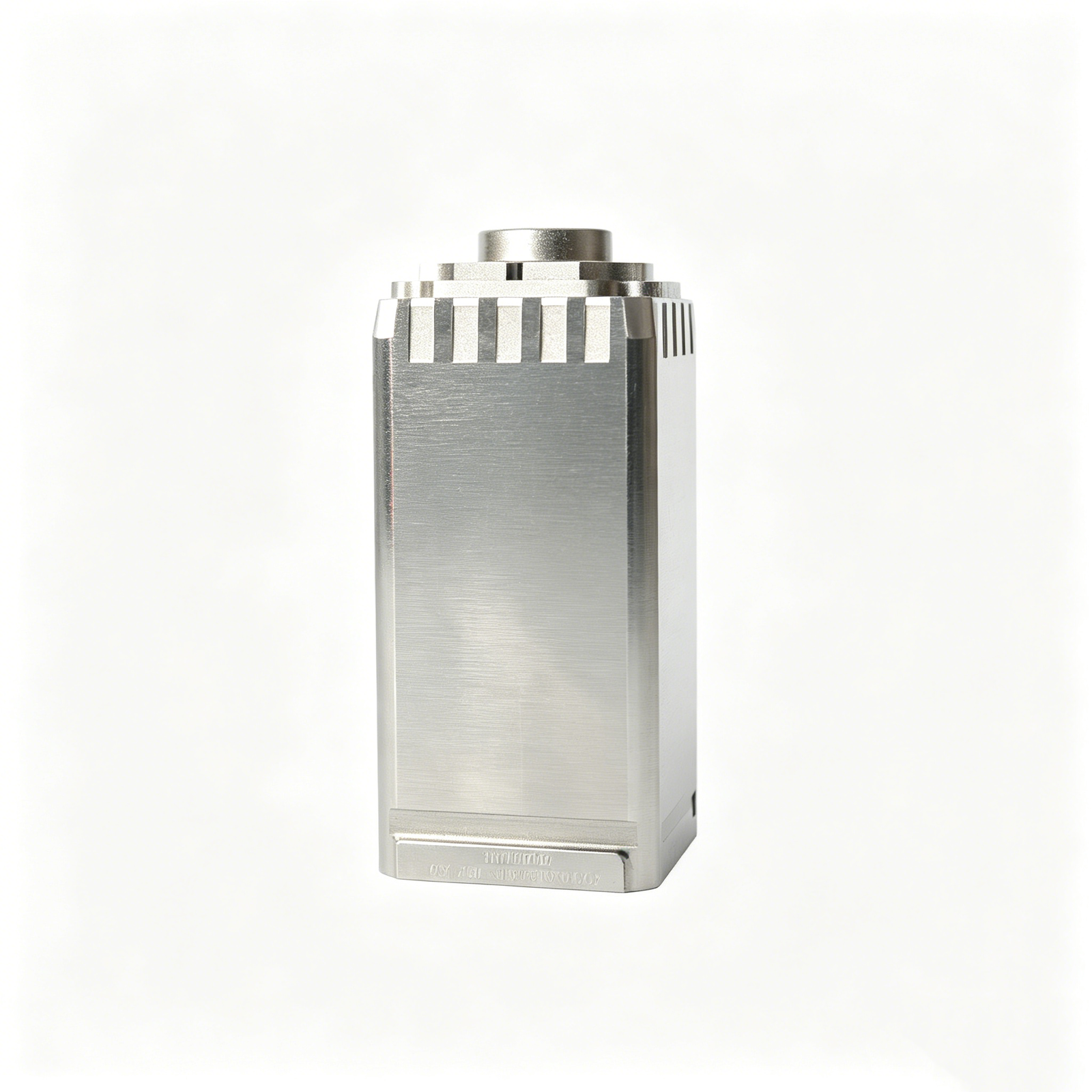
Representative Precision Components and Packaging Considerations





Related Precision Components and RFQ Options



Engineering Controls for Precision Part Packaging
Coordinate packaging requirements with the same drawing, quality, and revision discipline used to plan precision manufacturing work.
Drawing Comprehension
Review 2D drawings, models, quantities, and application context so handling and packaging requirements align with the part’s intended condition.
Critical Dimension Review
Identify datums, delicate features, surface priorities, and mating requirements early to help prevent avoidable handling risks after inspection.
Process-Route Planning
Coordinate CNC machining, EDM, grinding, fitting, and inspection sequence with the protection needs of sensitive finished features.
Inspection Planning
Define inspection methods and reporting expectations around critical characteristics, so verified part condition remains visible before delivery preparation.
Revision Control
Keep drawing revisions, approved changes, and order information visible throughout production to reduce confusion between released and superseded requirements.
Traceable Communication
Exchange material, quality, delivery, and packaging expectations clearly, giving engineering and sourcing teams a practical record for project coordination.
Precision Parts for Mold and Tooling Programs
Drawing-driven process routes for custom parts, mold components, connector tooling, and die components—reviewed against critical dimensions, material requirements, and inspection needs.

CNC Machining Services
Precision CNC machining services for drawing-based parts requiring coordinated milling, turning, EDM, grinding, fitting, and inspection. We review datums, critical dimensions, material, quantity, and quality requirements before defining a practical manufacturing route.
Upload a Drawing
CNC Milling
Custom CNC milling services for prismatic parts, plates, inserts, pockets, and formed features. Tool access, workholding, datum selection, machining allowance, and surface requirements are assessed against the supplied drawing and model.
Upload a Drawing
CNC Turning
Precision CNC turning services for shafts, pins, bushings, sleeves, and rotational features. Requirements are reviewed for concentricity, runout, diameters, threads, surface finish, material condition, and any downstream grinding or EDM operations.
Upload a Drawing
5-Axis Machining
5-axis CNC machining supports complex angled features, contoured geometry, and multi-face machining where fewer setups can protect datum relationships. Feasibility depends on tool reach, clamping strategy, feature geometry, material, and inspection access.
Upload a Drawing
Swiss & Micro Machining
Swiss machining and micro machining support small, slender, and detail-intensive parts where feature stability and handling matter. Provide dimensions, material, quantities, critical features, and mating context so the process route can be evaluated responsibly.
Upload a Drawing
Wire & Sinker EDM
Wire EDM and sinker EDM services address hardened materials, narrow slots, internal corners, deep ribs, intricate profiles, and features with limited conventional tool access. Electrode strategy, wire path, recast-layer considerations, and finishing requirements are reviewed per drawing.
Upload a Drawing
Precision Grinding
Precision surface and profile grinding supports controlled flatness, parallelism, profile accuracy, and finished dimensions on hardened or precision components. Grinding stock, heat-treatment sequence, datum references, and measurement method should be defined before production.
Upload a Drawing
Mold Core & Cavity Inserts
Precision mold core and cavity inserts are manufactured from customer drawings for injection-mold and related tooling applications. Critical shutoff geometry, cooling or feature access, material condition, EDM needs, fitting interfaces, and inspection priorities guide planning.
Upload a Drawing
Ejector & Ejection Components
Ejector pins, sleeves, and ejection components are made to drawing-defined dimensions and functional interfaces. Diameter, straightness, head geometry, fit, hardness requirements, and wear-sensitive surfaces require clear review with the corresponding mold design.
Upload a Drawing
Core Pins, Guide & Locating Components
Core pins, guide pins, and locating components are evaluated around alignment, clearance, wear, and mating-part relationships. Drawings should identify functional datums, toleranced diameters, material or heat-treatment needs, and any final grinding or polishing requirements.
Upload a Drawing
Slides, Lifters, Gates & Mold Accessories
Mold slides, lifters, gates, and accessories are configurable tooling components produced to the approved design. Motion interfaces, shutoff surfaces, guide relationships, clearances, material condition, and fitting requirements determine the appropriate machining and inspection plan.
Upload a Drawing
Connector Mold Components
Precision connector mold components support fine-pitch and mating-critical tooling work. Pin geometry, cavities, inserts, locating features, EDM details, surface condition, and dimensional relationships should be reviewed with connector design and production requirements.
Upload a Drawing
Stamping Die Components
Precision stamping die components are produced for drawing-based die assemblies, including punches, inserts, guide elements, and formed components. Material, hardness, edge condition, clearance relationships, grinding sequence, and inspection requirements are evaluated before commitment.
Upload a Drawing
Injection, MIM, CIM & Overmolding Tooling
Injection, MIM, CIM, and overmolding tooling components are supported when requirements fit verified production scope. Drawing review considers feed or gate features, shutoffs, inserts, ejection, material behavior, machining access, and downstream fitting or inspection needs.
Upload a Drawing
Machining Materials
CNC machining materials are selected against drawing requirements, functional loading, corrosion exposure, machinability, dimensional stability, and heat-treatment sequence. State the specified grade, condition, approved substitutions, and any material-documentation requirements in the RFQ.
Upload a Drawing
Surface Finishes & Heat Treatment
Surface finishing and heat treatment must be coordinated with dimensions, wear requirements, corrosion resistance, appearance, and subsequent grinding or EDM. Specify the required process, target condition, masking needs, surface priorities, and documentation expectations for review.
Upload a Drawing
Quality, Metrology & Documentation
Precision inspection, metrology, and quality documentation are planned around the order’s critical dimensions and approved inspection method. Define report requirements, datums, sampling expectations, material traceability, revision level, and any customer-specific records before production.
Upload a Drawing
Prototyping & Low-Volume Production
Rapid prototyping and low-volume manufacturing support drawing-based evaluation parts, tooling iterations, and controlled small-batch requirements. Include quantity, target date, material, critical dimensions, finish, inspection needs, and revision status to enable an informed review.
Upload a DrawingMaterials for Packaged Precision Components

Tool Steel
Common for mold cores, cavity inserts, slides and wear-critical tooling. Grade selection, hardness route, machining allowance and final grinding requirements should be reviewed against the drawing and mating-component conditions.

Stainless Steel
Used for corrosion-conscious mold components, guide elements and custom machined parts. Alloy choice affects machinability, heat treatment, surface condition and inspection approach, so requirements need confirmation during drawing review.

Aluminum Alloys
Often selected for prototypes, fixtures, lightweight tooling elements and machined housings. Alloy temper influences stability, thread strength, surface finishing and handling protection during precision part packaging and delivery planning.

Copper Alloys
Applicable to selected electrode, thermal-management and electrical-contact work where conductivity matters. Material grade, geometry, surface requirement and EDM or machining route require project-specific review before quotation.

Engineering Plastics
Suitable for selected fixtures, insulating elements, low-load components and prototype applications. Resin grade, dimensional stability, moisture sensitivity and critical surface requirements should be evaluated from the drawing and end-use context.
Manufacturing Processes for Precision Components

CNC Milling Turning
CNC milling and turning establish primary geometry, datum features, bores, threads, and profiles from the released drawing. Process planning considers tool access, clamping, machining allowance, and surface priorities before subsequent finishing operations.


Swiss Micro Machining
Swiss and micro machining are considered for small, slender, or detail-intensive turned components where support near the cutting zone matters. Drawing review confirms material, feature proportions, tolerances, surface requirements, and inspection method before quotation.

Wire EDM
Wire EDM produces precise profiles, slots, and hardened-material features without conventional cutting-force loading. The planned wire path, start-hole access, corner conditions, and required finish are reviewed alongside datum and inspection requirements.

Sinker EDM
Sinker EDM forms internal cavities, sharp-detail geometry, and inaccessible features using planned electrodes. Electrode strategy, spark allowance, surface condition, material state, and subsequent fitting or polishing requirements are aligned with the released drawing.

Precision Grinding
Precision grinding refines critical faces, diameters, and mating features after the appropriate machining or heat-treatment stage. The route accounts for grinding stock, datum strategy, surface specification, thermal condition, and the agreed inspection plan.
Component Features to Specify on Your Drawing

Locating Features
Dowel holes, locating faces and datum-related interfaces help establish repeatable component position during mold assembly. Define mating conditions, fit intent and critical dimensions so the feature can be assessed during drawing review.

Guide Components
Guide pins, bushes and guided interfaces support controlled movement between mold elements. Provide the mating geometry, material or heat-treatment requirements, lubrication considerations and positional tolerances for a suitable process review.

Ejection Details
Ejector-pin holes, return features, clearance zones and related ejection details are evaluated against component geometry and assembly function. Identify travel direction, mating parts and surface priorities to clarify machining access and inspection needs.

Gating Features
Gate inserts, runner-related details and flow-critical transitions may require specific EDM, milling or finishing strategies. Share the molding application, 3D model and surface requirements so tool access, electrode strategy and dimensional priorities can be reviewed.

Part Marking
Part numbers, revision identifiers and orientation marks can support receiving, assembly and traceability. State the marking method, location, character requirements and any protected surfaces on the drawing before production planning begins.
About SUUXIANG
SUUXIANG is the sole international-facing public brand of Dongguan SuuXiang Precision Mold Co., Ltd. Founded in 2010 by XiaoCheng Huang, its founder and legal representative, the company is based at 2nd Floor, Sanhe Industrial Park, Chang’an Town, Dongguan, Guangdong, China. We support global engineering and sourcing teams with drawing-driven production for custom CNC parts, precision mold components, connector tooling, and packaging requirements.
Our work starts before production: reviewing drawings, 3D models, material specifications, critical dimensions, datum strategy, surface requirements, and inspection expectations. Process planning can combine CNC milling and turning, multi-axis machining, EDM, grinding, fitting, and inspection according to the verified needs of the part.
What differentiates SUUXIANG is disciplined project control from DFM discussion through inspected delivery. We keep revision, machining-access, grinding-allowance, and documentation requirements visible, helping teams make informed decisions about protective handling and precision part packaging without overstating unverified capability.

Precision Part Packaging: From DFM to Inspected Delivery
Critical-Dimension Planning
Before quotation and production, SUUXIANG reviews the drawing, model, datums, tolerance stack, surface requirements, and mating context. This establishes which dimensions require focused process control and helps identify access, holding, and measurement risks before the route is committed.
- Identify critical-to-quality dimensions and datum relationships
- Review machining access, clamping, and tolerance-stack risks
- Confirm material, heat-treatment, and surface priorities
- Align inspection expectations with drawing requirements

EDM and Grinding Strategy
Complex precision components can depend on a deliberate combination of CNC machining, wire EDM, sinker EDM, and precision grinding. SUUXIANG evaluates electrode needs, wire paths, machining allowance, heat-treatment sequence, and grinding stock against the approved drawing.
- Plan EDM features around geometry and tool access
- Define machining allowance before finishing operations
- Consider heat treatment in the process sequence
- Reserve grinding stock for controlled final surfaces

Inspection Planned Upfront
Inspection is most useful when it follows the drawing’s critical features rather than becoming a final-stage formality. SUUXIANG aligns the inspection method, reporting needs, datum references, and traceability expectations with the verified order requirements before production proceeds.
- Link inspection points to critical drawing dimensions
- Clarify requested reports and measurement evidence
- Use drawing datums to guide measurement planning
- Match final documentation to the inspection plan

Revision-Controlled Coordination
Drawing-driven work can change quickly. SUUXIANG keeps revision information, technical questions, production status, and delivery requirements visible throughout project coordination, helping teams avoid producing to superseded data and maintain a clear record of the agreed manufacturing scope.
- Confirm the active drawing and model revision
- Record open technical questions before release
- Coordinate updates across production and inspection
- Maintain order-specific delivery information

Why Engineering Teams Use a Drawing-Driven Workflow
Compare a drawing-driven manufacturing workflow with a typical generic quotation process.
← Swipe left or right to view →
Controlled Production, Inspection and Pack-Out Process
Each order is planned from drawing review through inspection, protective packing and delivery coordination, with requirements and revisions kept visible throughout.
Review Drawings and Requirements
Review 2D drawings, models, material, quantity, critical dimensions, datums, surface priorities, inspection expectations and delivery requirements before confirming the manufacturing route.
Plan DFM and Process
Assess tool access, tolerance stack, machining allowance, heat-treatment sequence, electrode strategy and wire paths to identify practical controls before production begins.
Machine Critical Part Features
Apply the agreed CNC milling, turning, multi-axis, Swiss or micro-machining operations according to the approved drawing revision and documented process plan.
Finish With EDM Grinding
Use wire EDM, sinker EDM, precision grinding and fitting where required, managing finishing allowances and critical interfaces for the specified component function.
Inspect, Pack and Coordinate
Inspect against the verified plan, match documentation to the order, then prepare precision part packaging and coordinate delivery information for shipment.
From Drawing Review to Protective Pack-Out
Provide complete requirements early so SUUXIANG can align manufacturability, protection priorities, inspection planning, and delivery coordination before production begins.
Submit Your Drawing Package
Upload the 2D drawing and available 3D model, then identify the part application, quantity, revision level, target delivery date, and packaging-sensitive surfaces.
Confirm Critical Requirements
Specify material, heat treatment, critical dimensions, datum references, surface requirements, inspection reports, and handling or cleanliness needs that affect precision part packaging decisions.
Review the Manufacturing Path
SUUXIANG reviews DFM, machining access, EDM or grinding needs, tolerances, and inspection method, then clarifies open points before issuing a drawing-based quotation or sample path.
Approve Production Details
Confirm the quoted scope, revision-controlled requirements, quality plan, and delivery expectations so machining, inspection, and protective packing can proceed against an agreed project record.
Receive Inspected Parts
Production follows the approved process route, with final documentation matched to the verified inspection plan and shipment preparation aligned with the agreed handling requirements.
Certification and Quality Documentation
Project Evidence and RFQ Preparation
Customer feedback for precision part packaging is published only after project approval, with the applicable drawing revision, inspection scope, delivery record, and customer authorization available for review.
SUUXIANG does not publish anonymous performance figures or attributed customer statements without supporting project evidence. Request a drawing review to discuss packaging, handling, inspection, and documentation requirements.
For a relevant project discussion, provide the 2D drawing, quantity, material, critical dimensions, surface priorities, delivery target, and any packaging or traceability requirements before production planning begins.
Precision Part Packaging FAQ
Practical answers for teams sourcing drawing-based CNC parts, mold components, connector tooling, and die components.
What should I include in an RFQ for precision part packaging?
Can SUUXIANG quote low-volume precision part packaging projects?
How is precision part packaging specified for machined mold or connector components?
Do you provide samples before production?
What affects the lead time for custom CNC parts?
How should material and heat-treatment requirements be communicated?
Can I request inspection reports with my order?
How are parts prepared for international shipping and IP-sensitive projects?
The Complete Buyer’s Guide to precision part packaging
Use this decision framework to specify protective packaging, evaluate suppliers, control landed cost, and avoid handling, corrosion, contamination, traceability, and fit-related mistakes when sourcing drawing-based precision components internationally.
1. What Is precision part packaging?
1. Precision part packaging is an engineered protection and identification system that carries drawing-based CNC parts, mold components, connector tooling, stamping-die components, and prototypes from final inspection to their point of use. Its design begins with one question: which part conditions must remain unchanged until the receiver opens the shipment?
2. The answer can include geometry, critical surfaces, finish, cleanliness, corrosion condition, and, for sensitive assemblies, electrostatic-discharge control. A package must prevent part-to-part contact, abrasion, contamination, moisture exposure, or uncontrolled movement when those mechanisms could affect acceptance or assembly.
3. Packaging also sets the handling and receiving interface. Clear identification should connect the container to the part number, revision, quantity, order documentation, and any inspection or handling requirement, so receiving teams can verify status before parts enter stores, assembly, or a toolroom.
2. How precision part packaging evolved
1956 marked the start of containerized ocean freight at commercial scale, shifting machined parts from short domestic movements to multi-handling export routes. Basic paper wrapping and bulk cartons could prevent dirt, but rarely controlled part-to-part contact, humidity, or mixed-lot identification.
By the 1970s, higher-volume automotive and electronics supply chains drove fitted inserts, rust-preventive oils or vapor-corrosion inhibitors, and ESD-safe bags for sensitive assemblies. Those controls addressed vibration, corrosion, and static exposure as components traveled through varied environments (https://arrowpackagingsolutions.com/blog/precision-manufacturing-for-automotive-parts-why-expert-packaging-solutions-matter).
Today, 2D drawings should specify protected datums, cosmetic surfaces, pack quantity, orientation, corrosion-control period, ESD requirements, and label fields tied to revision and inspection records. Returnable dunnage supports repeat routes; export cartons or crates add handling and moisture protection so parts can move directly from receiving to assembly without losing traceability.
3. Types of precision part packaging
Precision part packaging should match geometry, shipment quantity, and the surfaces that cannot contact adjacent parts. The receiving question is practical: what separates, immobilizes, and releases each part without adding inspection work?
| Format | Best Fit | Strength | Limit |
|---|---|---|---|
| Individual bags or wraps | One-offs, pins | Low contact | Weak immobilization |
| Compartment trays | Small repeat parts | Count and separation | Fixed geometry |
| Foam or machined inserts | Polished complex parts | Positive location | Higher tooling cost |
| Clamshells or rigid carriers | Sensitive small lots | Rigid access control | Bulky shipment |
| Corrugated partitions | Robust production lots | Low-cost separation | Limited vibration control |
| Returnable containers or crates | Heavy repeat shipments | Durable protection | Return logistics |
Low-Volume Delicate Parts
One-off inserts, core pins, and polished components suit individual bags or wraps when contact must be minimized. They are economical but do not positively locate a part during rough transit.
Repeat-Use Production Packs
Repeated production lots favor trays, carriers, or returnable containers when each cavity defines orientation and count. These formats speed receiving, but require part-specific validation and return-loop control.
Bulk Shipment Decisions
Higher quantities can use corrugated partitions or crates when surfaces tolerate controlled separation and handling. Confirm whether operators must access one part at a time or unload the full pack.
4. Materials for precision part packaging
Two material decisions govern precision part packaging: protect the finished component and avoid changing its surface condition. Packaging material is selected for transport exposure; it is not a substitute for the specified part material, finish, or corrosion treatment.
| Material | Primary Protection Function | Limitations | Best-Fit Components |
|---|---|---|---|
| PE foam | Shock and abrasion isolation | May shed or trap contaminants | Machined housings, mold inserts |
| Corrugated board | Outer-carton strength and recyclability | Limited precision restraint | Bagged trays and boxed assemblies |
| Plastic trays | Repeatable separation and orientation | Higher tooling and freight volume | Pins, connectors, small inserts |
| Barrier bag plus desiccant | Moisture control | Requires seal integrity | Ground steel components |
| VCI-compatible wrap | Temporary corrosion protection | Verify chemical compatibility | Oiled ferrous parts |
| Anti-static film | ESD control | Not automatically corrosion protection | Electronic connector assemblies |
Match Protection To Geometry
Three contact risks—edge impact, surface rub, and movement—drive the selection of foam, formed plastic trays, corrugated board, tape, and void fill. Use low-lint, chemically compatible contact materials where polished, plated, or sealing surfaces require cleanliness.
Control Environmental Exposure
Two moisture controls, barrier bags and desiccants, limit humidity exposure during storage or export transit; validate the bag seal and desiccant quantity against route duration and pack volume. For corrosion-sensitive ferrous parts, confirm VCI compatibility with oils, coatings, cleaning residue, and the customer’s unpacking process.
One ESD requirement changes the pack specification: use dissipative or shielding materials for static-sensitive assemblies, then keep those materials segregated from ordinary foam and film. Record material type and revision on the packing instruction.
5. Custom precision part packaging options
One packaging drawing can define cavities, support points, separators and pack count before production. For precision part packaging, the purpose is controlled protection and traceability, not presentation.
| Control | Specification Input | Packaging Response |
|---|---|---|
| Surface protection | Finish and contact zones | Film or separated supports |
| Corrosion control | Material and route | VCI treatment where specified |
| Electrostatic control | ESD sensitivity | ESD-safe packaging materials |
| Traceability | Lot and revision fields | Labels with barcode or QR code |
Cavity And Contact Design
A 3D model and part drawing let the supplier locate cavity supports away from datums, sealing faces and cosmetic surfaces. Protective film, separators, VCI treatment or ESD-safe materials should match the material, finish and handling risk.
Lot And Identification Control
Each pack should state the approved quantity, lot or work-order identifier, part revision and handling direction. Barcodes or QR codes can link labels to inspection records when the buyer defines the required traceability fields.
Inputs For Packaging Review
An RFQ should include the drawing, critical dimensions, finish requirement, cleanliness level, destination, logistics route and units per pack. Inspection-report format and any assembly or unpacking instruction should be confirmed before release.
- 2D drawing and available 3D model
- Critical surfaces and contact restrictions
- Destination, route and pack quantity
- Label, barcode or QR data requirements
6. Precision part packaging quality elements
Two pack-out checks matter: the package must preserve the final inspected condition and make any mix-up visible. For precision part packaging, protection is a controlled extension of release, not a substitute for inspection.
Retention And Surface Separation
Each part needs positive retention that prevents movement without concentrating force on a datum, polished face, thread, or sharp edge. Individual cavities, dividers, sleeves, or caps should keep parts from touching.
- Check no critical surface contacts retention points.
- Verify caps and edge guards stay fitted.
- Shake-test a representative closed pack.
Environment And Closure Control
One clean barrier layer can limit particulate transfer; corrosion-sensitive material may require a specified protective method matched to storage and transit conditions. Closure must remain secure through handling and normal stacking.
- Inspect bags, wraps, and cushioning for debris.
- Confirm closure, orientation, and handling marks.
- Check carton compression and internal clearance.
Repeatable Release Evidence
Every pack should match the approved pack-out instruction: quantity, orientation, separators, label, and final-inspection status. At receiving, compare the label and inspection documentation with the purchase order, revision, lot, and actual count.
- Read labels without opening the pack.
- Record damage before unpacking.
- Quarantine mixed, wet, or unsealed packs.
7. Choosing a precision part packaging supplier
Choose a supplier that treats packaging as a controlled engineering deliverable, reviewed alongside the drawing and delivery route. Broad claims are insufficient; request job-specific records before releasing production.
| Evidence | What To Verify | Why It Matters |
|---|---|---|
| Pack instruction | Revision and pack sequence | Repeatable shipment preparation |
| Sample approval | Photos and buyer sign-off | Validates fit before release |
| Traceability record | Part, lot, and shipment link | Supports claim investigation |
Verify Engineering Review
2D drawings should identify cosmetic, datum, sealing, and corrosion-sensitive features before pack design. Ask who approves orientation, contact points, and handling restrictions.
1 sample pack should be reviewed with the first article or prototype. Require photographs showing each layer, labels, and part identification.
Request Controlled Evidence
1 packaging work instruction should state materials, pack quantity, orientation, label data, and revision. Ask for material specifications, lot linkage, inspection records, and export-packaging experience.
24-hour acknowledgement of a damage claim is a practical communication expectation; agree containment, evidence collection, corrective action, and replacement ownership in advance.
Ask RFQ Questions
3 RFQ questions expose whether a supplier has a usable control plan rather than a generic promise.
- Which critical surfaces must never contact packaging?
- Can you submit a sample-pack approval record?
- How are packaging revisions and damage claims traced?
8. Common precision part packaging mistakes
Packaging decisions made after final inspection often miss surface sensitivity, handling routes, and documentation needs. Treat the pack-out as a controlled part of the delivery plan.
Prevent Part-To-Part Damage
Contact-sensitive pins, ground inserts, and polished cavities can fret or nick in bulk packs. Specify individual separation, restrained orientation, and a pack quantity that prevents movement.
- Define maximum pieces per tray or bag
- Protect datum and sealing surfaces first
- Verify retention after normal handling
Control Environment And Transit
Steel parts can corrode when moisture control is omitted, while electronics-related components may need ESD protection. Match barrier materials, desiccant, ESD controls, and outer protection to transit mode, storage time, and climate.
- State sea, air, or mixed transit
- Identify humidity and temperature exposure
- Confirm corrosion-prevention compatibility
Approve Traceable Pack-Outs
Labels without part number, drawing revision, quantity, and lot identification complicate receiving and containment. Approve a representative pack-out sample, then compare packaging cost against damage, sorting, rework, and schedule impact.
- Record revision and lot on labels
- Photograph the approved pack-out
- Revise packaging after engineering changes
9. Launching precision part packaging
A controlled launch converts packaging from a late shipping task into an approved production condition. SUUXIANG should review it alongside the drawing revision, part risk, destination, and receiving criteria before quoting.
Define The Packaging Risk
1. Start with part geometry, finish sensitivity, corrosion exposure, weight, and handling points. Set the acceptance criteria: no contact on critical surfaces, no mixed revisions, and no visible transit damage.
- Drawing revision and part number
- Quantity per pack and maximum carton weight
- Destination, transport mode, and storage duration
Approve The Pack-Out
2. Request a quotation and pack-out proposal showing materials, nesting orientation, corrosion protection, outer carton, and label format. Approve a prototype or first-article pack-out against the actual inspected part before release.
Validate Transit And Instructions
3. Match validation to risk: fragile, polished, or long-distance shipments require a documented handling and transit check. Release a work instruction only after the buyer accepts photos, packing sequence, label fields, and closure method.
- Part number, revision, lot, and quantity
- Purchase order and destination
- Handling marks and inspection status
Pilot And Production Release
4. Ship a pilot lot, then record receiving feedback on damage, count accuracy, cleanliness, and label readability. Release controlled production only when both parties close deviations and lock the approved packaging revision.
10. Precision part packaging pricing and cost
1 packaging quote should separate recurring pack-out cost from nonrecurring insert, fixture, label-artwork, or crate-development cost. Part count, geometry, critical surfaces, material condition, and required ESD or corrosion controls determine the protection specification.
2 freight comparisons must include pack density, carton or export-crate dimensions, gross weight, labels, inspection records, and packing labor. Replenishment volume can amortize approved insert development, while low-volume orders should retain a visible setup line.
| Quantity tier | Packaging complexity | Unit-cost direction | Setup-cost exposure | Typical lead-time implication |
|---|---|---|---|---|
| 1–10 sets | Individual wraps, custom cavities, documents | Highest | High per set | Design review and sample approval may extend release |
| 11–100 sets | Partitioned trays, corrosion or ESD controls | Declining | Moderate | Standard materials can shorten preparation |
| 101–500 sets | Repeatable inserts, batch labels, denser cartons | Lower | Spread across batch | Production packing can run with part completion |
| 500+ sets | Returnable or dedicated packs, optimized freight density | Lowest | Amortized | Replenishment planning reduces changeover time |
Precision Part Packaging Starts With Your Drawing
Submit your drawing, material, quantity, critical dimensions, inspection needs, and target delivery date for a disciplined project review.