
Quality Assurance System for Precision Parts
From drawing review through machining, EDM, grinding and inspection, our quality assurance system keeps critical dimensions, revisions and documentation aligned.
Representative Precision Components


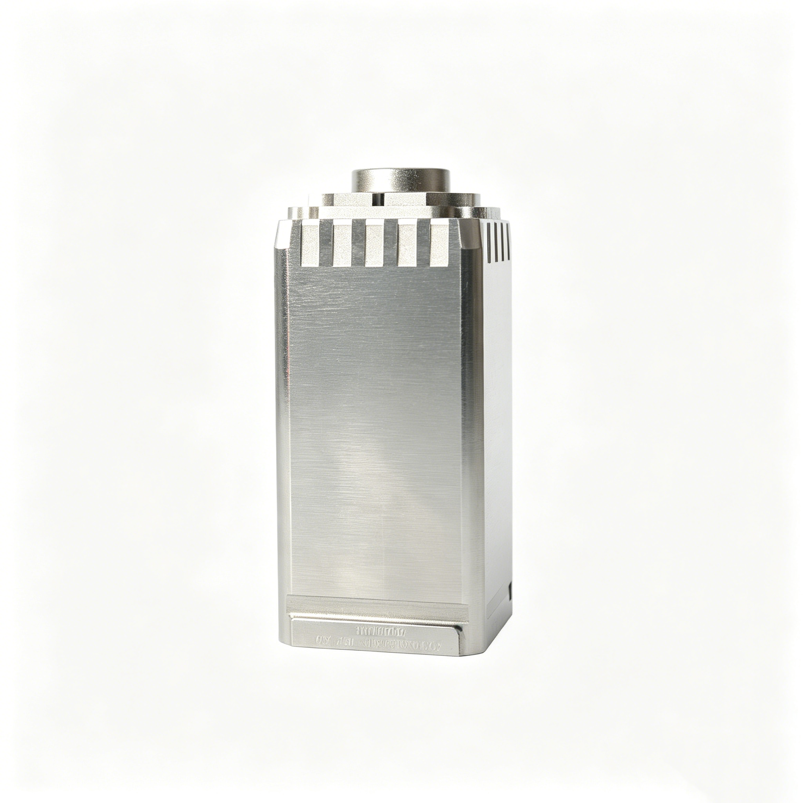


Drawing-Based Parts: Request a Quote






Controls for Drawing-Based Production
Drawing-led planning helps align critical requirements, process decisions, inspection evidence, and revision visibility before production moves forward.
Drawing Review
Review drawings, models, materials, and application context to identify missing information before quotation and production planning begin.
DFM Input
Discuss machining access, datum strategy, tolerance stack, and process constraints so manufacturability questions are visible early.
Critical Dimensions
Identify critical-to-quality dimensions, surface priorities, and relevant measurement methods to shape a practical inspection plan.
Process Routing
Plan suitable CNC, EDM, grinding, fitting, and heat-treatment sequences around geometry, allowances, and specified requirements.
Inspection Planning
Match final documentation to the order and verified inspection plan, with attention to required reports and acceptance criteria.
Revision Visibility
Keep drawing revisions, project information, and delivery coordination visible so approved requirements remain connected throughout production.
Precision Manufacturing Product Families
Drawing-driven process routes for custom parts, mold components, connector tooling, and controlled prototype or low-volume production.

CNC Machining Services
Precision CNC machining services for drawing-based parts that require a defined route through milling, turning, EDM, grinding, fitting, and inspection. Review focuses on datums, critical dimensions, material condition, tool access, surface requirements, and the evidence needed before production is committed.
Upload a Drawing
CNC Milling
Custom CNC milling services for prismatic, contoured, and multi-feature components. Toolpaths, fixturing, datum access, wall geometry, and machining allowance are reviewed against the drawing so dimensional priorities can be carried through machining and inspection.
Upload a Drawing
CNC Turning
Precision CNC turning services for rotational parts with controlled diameters, concentric features, threads, bores, and sealing or mating surfaces. The production review considers datum selection, runout requirements, material condition, finishing operations, and inspection methods appropriate to the part.
Upload a Drawing
5-Axis Machining
5-axis CNC machining for complex surfaces and features that benefit from reduced setups and improved tool approach. Each route is assessed for fixture access, cutter reach, surface transition requirements, datum control, and whether simultaneous machining is appropriate for the specified geometry.
Upload a Drawing
Swiss & Micro Machining
Swiss machining and micro machining for small, slender, or feature-dense parts where support, concentricity, and handling require careful planning. Drawing review addresses stock diameter, critical cross-features, burr control, inspection access, and the practical limits of material and feature geometry.
Upload a Drawing
Wire & Sinker EDM
Wire EDM and sinker EDM services for hardened details, narrow profiles, internal corners, cavities, and features with limited conventional tool access. Electrode strategy, wire path, flushing, recast-layer considerations, finishing allowance, and subsequent inspection are defined from the part requirements.
Upload a Drawing
Precision Grinding
Precision surface and profile grinding for flatness, parallelism, profile accuracy, and controlled final stock removal. Process planning considers heat-treatment sequence, grinding allowance, datum stability, burn risk, surface requirement, and the inspection method for critical geometry.
Upload a Drawing
Mold Core & Cavity Inserts
Precision mold core and cavity inserts produced from drawings and 3D models for injection-molding tool assemblies. Manufacturing planning addresses steel selection, heat-treatment sequence, parting and shutoff geometry, EDM access, grinding stock, cooling-related features, and fit with mating components.
Upload a Drawing
Ejector & Ejection Components
Ejector pins, sleeves, and ejection components for controlled mold movement and part release. Requirements are reviewed for diameter and clearance relationships, head or seat geometry, hardness condition, surface needs, stroke-related fit, and compatibility with the surrounding ejection system.
Upload a Drawing
Core Pins, Guide & Locating Components
Core pins, guide pins, and locating components manufactured around the dimensional relationships that control mold alignment and formed features. Review covers datum strategy, concentricity, fit class, wear surfaces, heat treatment, grinding requirements, and mating-part information.
Upload a Drawing
Slides, Lifters, Gates & Mold Accessories
Mold slides, lifters, gates, and accessories for moving actions, part release, and material-flow functions within tooling. Production review focuses on travel and clearance, contact surfaces, shutoffs, angle relationships, wear considerations, machining access, and assembly-level mating conditions.
Upload a Drawing
Connector Mold Components
Precision connector mold components for high-density, fine-feature, and repeatable connector tooling. The drawing review examines pin and cavity geometry, pitch-critical relationships, datum transfer, EDM or grinding needs, material treatment, surface condition, and inspection access.
Upload a Drawing
Stamping Die Components
Precision stamping die components for blanking, forming, guiding, and locating operations. Process routes are planned around punch and die geometry, clearance relationships, working-edge condition, hardness and coating requirements, grinding stock, and fit with related die-set components.
Upload a Drawing
Injection, MIM, CIM & Overmolding Tooling
Injection, MIM, CIM, and overmolding tooling components for applications within verified production scope. Drawing review considers material flow interfaces, cavity and core geometry, insert relationships, shrinkage-related inputs supplied by the customer, tool access, finishing, and inspection requirements.
Upload a Drawing
Machining Materials
CNC machining materials selected against the drawing, functional environment, heat-treatment route, and dimensional priorities. Buyers should identify the specified grade, material condition, certification needs, corrosion or wear demands, and any material substitutions requiring approval before quotation.
Upload a Drawing
Surface Finishes & Heat Treatment
Surface finishing and heat treatment planned as part of the dimensional process route, not as an afterthought. Requirements may affect machining allowance, masking, edge condition, hardness verification, surface roughness, corrosion resistance, and final inspection criteria.
Upload a Drawing
Quality, Metrology & Documentation
Precision inspection, metrology, and quality documentation aligned to the order and agreed inspection plan. Critical dimensions, datums, sampling expectations, measurement methods, revision status, material or treatment records, and requested reports should be defined before production begins.
Upload a Drawing
Prototyping & Low-Volume Production
Rapid prototyping and low-volume manufacturing for teams validating geometry, fit, assembly, or early production requirements. A drawing-based review clarifies material, critical dimensions, surface priorities, revision control, inspection needs, delivery target, and the process route suitable for the requested quantity.
Upload a DrawingMaterial Planning Before Production

Tool Steels
Common for mold cores, cavity inserts, slides and die components where wear resistance and stability matter. Machining allowance, heat-treatment sequence and final grinding strategy should be defined before critical dimensions are inspected.

Stainless Steels
Used for precision components requiring corrosion resistance or controlled surface condition in mold and connector-tooling applications. Grade, hardness condition, machining access and measurement method should be aligned with the drawing and operating environment.

Aluminum Alloys
Suitable for lightweight fixtures, prototypes and selected mold-related components where fast machining is valuable. Alloy temper, thread strength, surface protection and datum handling influence process planning and inspection of functional features.

Copper Alloys
Applied to selected inserts and components where thermal or electrical performance affects the design. Material grade, electrode strategy, burr control and surface requirements require clear definition so inspection focuses on the dimensions that govern fit.
Process Routes for Controlled Manufacturing

CNC Milling
CNC milling shapes pockets, contours, faces and mold-component geometry from the approved drawing and model. Tool access, holding strategy and machining allowance are reviewed to support controlled dimensions and specified surface requirements.

CNC Turning
CNC turning produces concentric diameters, threads, bores and rotational features for custom precision parts. The route considers datum references, runout-sensitive features and subsequent milling, EDM or inspection needs before setup planning.


Wire EDM
Wire EDM cuts precise profiles, slots and internal features where conventional tool access is limited. Wire path, start-hole requirements, datum transfer and finishing strategy are aligned with the part geometry and inspection plan.

Sinker EDM
Sinker EDM forms cavity details, sharp internal geometry and deep features through planned electrode strategy. Electrode design, spark allowance, surface expectations and post-EDM finishing requirements are reviewed before the route is released.

Grinding and Inspection
Precision grinding, fitting and inspection complete process routes for critical surfaces, mating relationships and documented verification. Grinding stock, measurement method, report requirements and revision status are coordinated against the approved quality plan.
Configured Mold Components

Guide Components
Guide pins, bushes, and locating features establish repeatable alignment between mold elements. Drawing review should define datums, fits, surface requirements, and inspection points where guided motion or positional repeatability affects assembly.

Ejection Elements
Ejector pins, sleeves, and related ejection components are configured around stroke, clearance, hardness, and contact conditions. Critical diameters, concentricity, surface finish, and mating details should be identified before machining and inspection planning.

Gate Inserts
Gate inserts and related flow-entry details support injection-mold tooling configurations. Their geometry requires clear definition of material, heat-treatment sequence, EDM strategy, polishing requirements, and interfaces with adjacent cores, cavities, or runners.

Slides and Lifters
Slides, lifters, and moving mold components require coordinated attention to travel, locking, wear surfaces, and assembly relationships. SUUXIANG reviews machining access, grinding stock, electrode needs, and critical locations against the supplied drawing.

Configured Accessories
Mold accessories such as locating blocks, wear plates, stops, and custom support elements can be produced to drawing-defined requirements. The quality assurance system aligns revision control, critical dimensions, and required inspection documentation with the order.
A Quality Assurance System Built Around Drawings
SUUXIANG is the international-facing brand of Dongguan SuuXiang Precision Mold Co., Ltd., established in 2010 in Chang’an Town, Dongguan, Guangdong, China. Founded by XiaoCheng Huang, the company helps global engineering, sourcing, and quality teams translate drawings and specifications into inspected custom parts, precision mold components, connector tooling, and die components.
Our quality assurance system begins before production commitments: drawing and DFM review, critical-dimension and datum discussion, material and heat-treatment requirements, and an inspection plan aligned to the order. CNC machining, EDM, grinding, fitting and inspection are planned as connected steps, not isolated operations.
What distinguishes SUUXIANG is disciplined project coordination for drawing-driven work. We make machining access, electrode and wire-path needs, grinding stock, revision status and reporting expectations visible early, so teams can make informed manufacturing decisions and exchange the evidence needed to proceed responsibly.

How Our Quality Assurance System Works
DFM Before Commitment
Each project begins with the drawing, model, material, quantity, application, and quality requirements. SUUXIANG reviews critical dimensions, datum strategy, tolerance stack, tool access, surface requirements, and feasible inspection needs before quotation or production commitments.
- Identify critical-to-quality dimensions and functional datums
- Review machining access, tolerance stack, and surface callouts
- Clarify material, heat treatment, quantity, and application context
- Define open technical points before release

Process Routes Match Geometry
The quality assurance system connects part geometry to a practical process route. CNC machining, wire or sinker EDM, precision grinding, fitting, and intermediate checks are selected according to access, hardness sequence, feature geometry, and the dimensions that matter most.
- Plan machining, EDM, grinding, and fitting in sequence
- Assess electrode strategy and wire-path requirements
- Protect critical features through appropriate setup planning
- Confirm allowances before finishing operations

Inspection Plans Follow Risk
Inspection is planned around the approved drawing and verified project requirements, not treated as a final-stage formality. Measurement methods, critical features, reporting expectations, and documentation are aligned before production so evidence can match the order’s inspection plan.
- Prioritize critical dimensions and mating features
- Align measurement methods with drawing requirements
- Define required reports before production begins
- Match final documentation to verified inspection scope

Revisions Stay Visible
Drawing-based precision work depends on disciplined revision control and clear project coordination. SUUXIANG keeps manufacturing and delivery information visible as requirements develop, helping teams confirm the released revision, resolve questions early, and avoid producing against outdated specifications.
- Confirm the production-release drawing revision
- Track clarification items and approved changes
- Coordinate inspection and delivery requirements
- Keep technical communication traceable throughout the project

Why Engineering Teams Choose SUUXIANG’s Quality Assurance System
Use these criteria to evaluate drawing review, process planning, revision control, and inspection documentation when comparing potential suppliers.
← Swipe left or right to view →
Controlled Manufacturing Process Within Our Quality Assurance System
Each drawing-driven order follows a defined review, process-planning, production, inspection, and delivery-coordination sequence aligned to the approved project requirements.
RFQ and Drawing Review
We review drawings, models, material, quantity, application context, critical dimensions, surface requirements, delivery target, and requested inspection documentation before discussing a production route.
DFM and Process Planning
The team confirms datum strategy, tolerance stack, machining access, heat-treatment sequence, machining allowance, EDM requirements, grinding stock, and inspection approach against the current revision.
CNC Machining and EDM
Parts proceed through the applicable CNC milling, turning, multi-axis machining, wire EDM, or sinker EDM operations according to the reviewed process plan and drawing requirements.
Grinding and Component Fitting
Where required, precision grinding and fitting address functional surfaces, mating relationships, and controlled stock removal while maintaining visibility of critical features and approved revisions.
Inspection and Documentation Review
Inspection follows the verified order requirements and inspection plan, with dimensional results and final documentation reviewed for alignment with the drawing, revision, and agreed reporting needs.
Packing and Delivery Coordination
Accepted parts are prepared for shipment with project information coordinated against the order, packaging needs, delivery arrangement, and any documentation required for customer receipt.
Work Through a Quality Assurance System
Move from drawing review to order-matched inspection documentation with defined technical inputs, revision visibility and production coordination.
Submit Complete Requirements
Provide 2D drawings, 3D models when available, material, quantity, delivery target, critical dimensions, surface needs and required inspection or reporting expectations.
Align DFM and Quotation
Review datum strategy, tool access, machining allowances, EDM or grinding needs, heat-treatment sequence, inspection approach and revision details before quotation commitments are confirmed.
Approve Production Readiness
Confirm the agreed technical route, applicable sample or production requirements, and current drawing revision so manufacturing can proceed through controlled CNC, EDM, grinding and fitting operations.
Receive Inspected Parts
Receive parts with final documentation matched to the order and verified inspection plan, alongside clear communication for delivery coordination and any approved revision records.
Certificates and Documentation: Verify by Project
Customer Evidence Is Published Only When Verified
Customer testimonials are published only with permission and project-specific evidence.
Approved case studies describe the relevant part family, inspection method, revision coordination, and outcome without disclosing customer-controlled information.
SUUXIANG publishes performance claims only when they are traceable to the applicable order requirements and final inspection documentation.
Quality Assurance System FAQ for RFQs
Practical answers for engineering, sourcing, and supplier-quality teams evaluating drawing-based precision parts.
What should I include in an RFQ for inspected CNC parts?
How does a quality assurance system affect the quotation review?
Is there a minimum order quantity for precision mold components?
Can I request samples before a production order?
What inspection reports can a quality assurance system provide?
How does your quality assurance system control drawing revisions?
How are lead times assessed for custom CNC and EDM parts?
How are payment, shipping, and intellectual property handled?
Complete Buyer’s Guide to Quality Assurance Systems
Use this decision framework to evaluate supplier quality assurance systems for inspected CNC and tooling parts, compare evidence and controls, define acceptance criteria, and avoid sourcing mistakes that cause defects, delays, and undocumented risk.
1. What Is a Quality Assurance System?
A quality assurance system for CNC parts, mold components, connector tooling, and low-volume builds uses the released drawing and applicable specifications as controlled references. It organizes documented requirements, process planning, revision control, verification, nonconformance handling, and improvement so conformance is designed into the workflow rather than assumed at shipment.
QA is preventive: it defines how critical dimensions, datums, material condition, machining sequence, EDM or grinding allowances, and inspection methods will be controlled before work begins. QC verifies output through measurement or testing against acceptance criteria and records the result; both operate within the broader quality-management system.
A rejected measurement should trigger containment, documented disposition, and root-cause review or corrective action proportionate to the risk. For a drawing-based supplier, practical evidence links the current revision and process records to the verified inspection plan and final documentation.
2. How Quality Assurance Evolved
Early production-management practices emphasized repeatable methods, standardized work, and consistency rather than relying solely on individual craftsmanship. For precision parts, that shift made documented dimensions, work instructions, and comparable outputs increasingly important.
During the twentieth century, statistical quality-control methods expanded the use of process data and sampling to distinguish normal variation from special causes. These practices helped establish more formal manufacturing quality systems built around standardized processes.
Today, risk-based planning and digital records connect drawing revisions, material identification, inspection results, nonconformities, and corrective actions across global supply chains. Final inspection still verifies the delivered part, but early review of datums, process risks, machining access, and measurement methods can prevent a part that appears conforming from failing its functional or assembly requirement.
3. Quality Assurance System Models Compared
Six models can be combined; no single framework controls every precision-part risk. Select them from drawing complexity, customer requirements, and available production evidence.
| Model | Purpose | Strongest Use | Buyer Evidence | Limitation |
|---|---|---|---|---|
| Process-based QA | Control each operation | Repeatable routed parts | Flow, travelers | May miss unique risks |
| Standards-based | Structure management system | Supplier comparison | Scope, audit records | Certificate alone proves little |
| Risk-based planning | Prioritize failure risks | Tight datums, EDM | Risk plan, controls | Depends on current review |
| QC integration | Verify planned outputs | Critical dimensions | Inspection plan, reports | Inspection cannot prevent all defects |
| Continuous improvement | Remove recurring causes | Repeat work | NCR, corrective actions | Needs trend data |
| Customer-specific planning | Meet contract requirements | Connector or mold programs | CTQ matrix, revision log | Can add cost and lead time |
QA And QC Roles
QA defines preventive controls: drawing review, approved routing, revision control, and inspection planning. QC verifies output through measurement, records nonconformities, and feeds results back to QA.
Two roles must remain connected: a passed final inspection cannot repair an uncontrolled heat-treatment sequence or wrong drawing revision.
4. Quality Assurance System Documentation
A quality assurance system for drawing-controlled parts is only useful when records identify the exact revision, lot, process checks, and shipment. Documentation should be agreed during drawing review, before production starts.
| Part Risk | Typical Documentation | Release Basis |
|---|---|---|
| Prototype | Drawing revision and final report | Agreed dimensions |
| Tight-tolerance part | Material, first-article, in-process records | Control-plan results |
| Regulated or critical part | Lot traceability, calibration, NCR/CAPA | Defined customer requirements |
Core Record Set
A 2D drawing and its linked 3D model require revision control, approval status, and distribution discipline. The control plan and inspection plan should identify critical dimensions, datums, methods, sampling, and acceptance criteria.
- Incoming-material certificate or traceable lot record
- First-article, in-process, and final inspection reports
- Calibration status for measurement equipment used
- NCR and CAPA records when deviations occur
Documentation By Risk
Tight tolerances, heat-treated materials, safety-relevant applications, and regulatory obligations justify deeper evidence. A low-risk prototype may need final measurements; a critical connector-tooling component may require material, process, and dimensional traceability.
Shipment Traceability
Each shipment record should connect the purchase order, drawing revision, quantity, inspection release, and package identification. Buyers should define required report formats and retention expectations in the RFQ.
5. Materials and Measurement Controls
For every drawing-based order, material and measurement requirements must become records checked before release. SUUXIANG should align the inspection plan with critical dimensions, functional interfaces, and the approved revision.
| Drawing Requirement | Acceptance Evidence | Typical Method |
|---|---|---|
| Material grade | Certificate and heat or lot ID | Document review |
| Hardness or coating | Specified value and report | Defined test method |
| Datum-related geometry | Measured result to drawing | CMM or functional gage |
Material Identity
Each material callout should state grade, condition, approved source evidence, and the required heat or lot identifier. A material certificate should be reviewed against the purchase requirement before machining begins.
Thermal And Coating Records
When a drawing specifies hardness, heat treatment, or coating, define the test method, location, acceptance range, and required report. Any material substitution needs documented customer approval before it changes machining, EDM, grinding, or performance assumptions.
Measurement Method Fit
Critical dimensions need an inspection method matched to geometry: calibrated micrometers for external sizes, CMM for positional relationships, and suitable surface measurement for finish. Functional interfaces should be checked against their mating datum scheme, not isolated dimensions alone.
6. Quality Assurance System for Custom Parts
Custom parts require a quality assurance system that converts each drawing-specific requirement into a controlled record before material is cut. Prototype urgency does not justify undocumented instructions or unapproved assumptions.
Quote-Stage Review
At quotation, review datums, critical dimensions, tolerance stack, tool access, material condition, heat-treatment sequence, EDM or grinding allowance, and inspection method. Record unresolved items as RFQ questions rather than relying on verbal direction.
Revision And First-Article Gates
Before production, identify the drawing revision, model revision, and approved deviations on the order record. For first articles or approved samples, define the measurements, report format, buyer acceptance gate, and release authority before subsequent parts proceed.
Measurement And Change Control
For low-volume work, plan fixtures and gauges around the stated datum scheme and feature accessibility. Any change to material, process route, electrode strategy, finish, marking, or cosmetic acceptance criteria needs documented buyer signoff and appropriate special-process verification.
7. Critical Construction Quality Elements
Functional datums should establish how the part is located in manufacture and in its mating assembly. A quality assurance system should concentrate evidence on features whose variation changes fit, sealing, motion, electrical position, or tool life.
Datums And Functional Tolerances
Three datum references are often enough to constrain a prismatic part; confirm that drawing datums match inspection fixturing.
Each GD&T callout needs a stated datum order, measurement method, and applicable condition before release.
Feature Risk Priorities
Five checkpoint groups usually deserve priority: locating features, mating diameters, threads, flatness, and concentricity.
Every remaining feature need not receive identical inspection frequency; rank it by functional consequence, process risk, and detectability.
- Critical-to-function dimensions
- Fit and thread gauges
- Burr and edge-break condition
- Surface finish and cleanliness
Process Effects And Protection
Heat treatment and plating can change size, hardness, surface condition, or thread fit; define final-state acceptance dimensions.
Clean, separated packaging protects finished edges and bearing surfaces during shipment, while preserving part identification and revision traceability.
8. Choosing a Quality-Assured Manufacturer
Two evidence sets should drive supplier selection: the quoted process route and the records proving it was followed. Ask for project-specific evidence before awarding a drawing-based order.
| Evaluation Area | Ask For | Warning Sign |
|---|---|---|
| Capability | Comparable process evidence | Generic capability list |
| Measurement | Calibration records | Unstated measurement method |
| Revision Control | Release record | Email-only changes |
| Corrective Action | Root-cause response | Replacement without analysis |
Verify Process Ownership
Three questions expose ownership: Who approves the inspection plan, who releases revisions, and who closes nonconformities?
One warning sign is a supplier that offers certificates but cannot identify the responsible role, controlled drawing revision, or corrective-action due date.
- Request a current equipment list
- Request calibration status and scope
- Request a sample inspection report
- Ask how subcontracted processes are controlled
Control Samples And Delivery
First articles should have defined acceptance criteria, measurement methods, and written approval status before repeat production.
Two lead-time questions matter: What operation sets the critical path, and what event triggers an immediate delay notice? Avoid commitments detached from material, heat treatment, EDM, grinding, or inspection capacity.
- Match reports to drawing revision
- Require lot or job traceability
- Define deviation approval authority
9. Quality Assurance System Mistakes
A quality assurance system fails when buyers substitute paperwork or end-of-line checks for controlled requirements. Eight recurring errors create avoidable rework, disputes, and delivery risk in drawing-based parts.
Certification Is Not Conformance
ISO certification shows a management-system framework, not that a specific part meets its drawing. Require the order-specific inspection plan, material evidence, and dimensional results before release.
Unclear Drawings Create Assumptions
Missing datums, critical dimensions, or measurement methods force suppliers to choose interpretations. Mark CTQ features, define datum references and gauges, and resolve ambiguous notes during drawing review.
Material And First Article Gaps
Undocumented substitutions can change hardness, machining response, fit, or service behavior; skipping first-article approval can repeat the error across a lot. Lock approved material and heat-treatment requirements, then approve a measured first article before production.
Informal Changes And Lowest Price
Email-only revision changes and unit-price-only selection obscure accountability and often shift cost into rework, sorting, or delays. Use revision-controlled documents, acknowledge every change, and compare process route, inspection evidence, lead time, and total risk.
10. Quality Assurance System Cost Factors
Two cost buckets should be separated during RFQ review: recurring per-part controls and one-time planning work. A quality assurance system quote should identify which inspection, reporting, traceability, and process steps apply to the drawing revision.
Four downstream exposures—defect containment, rework, delivery delay, and assembly failure—often outweigh an initially lower inspection scope. Compare the added control cost with the consequence of an escaped nonconformance in the mating assembly.
| Cost and schedule driver | Lower-impact requirement | Higher-impact requirement | Commercial effect |
|---|---|---|---|
| Quantity tier | Repeat production quantity | Prototype or small lot | Setup and first-part effort spread over fewer parts |
| Inspection level | General dimensional checks | Critical-dimension plan or 100% verification | More measurement time and possible fixture planning |
| Report type | Conformance confirmation | Dimensional report, material record, or photo evidence | Preparation, review, and document-control time increase |
| Material traceability | Standard material identification | Heat or batch traceability matched to order | Record collection and segregation add handling |
| First article and processes | No formal first article; standard route | First-article approval, EDM, grinding, heat treatment, or coating | Planning, outside-process coordination, and schedule risk increase |
| Lead time | Planned production window | Expedited completion | Capacity prioritization and inspection timing may add cost |
Submit Your Drawing for Technical Review
Upload 2D or 3D files with material, quantity, critical dimensions, quality expectations, and target delivery date for a technical review.