
Thread and Gauge Inspection for Precision Parts
Send your drawing for DFM review, process planning, and thread and gauge inspection aligned with critical dimensions and documentation needs.
Representative Parts and Tooling for Inspection Planning





Related Drawing-Based Parts and Tooling


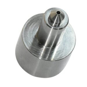


Thread and Gauge Inspection Advantages for Critical Features
Engineering review connects feature intent, process routing, inspection evidence, and revision visibility before production commitments are made.
DFM Before Quotation
Review drawing requirements, critical dimensions, material, and access constraints early to identify manufacturability questions before process commitments are made.
Datum-Aware Planning
Align machining and thread and gauge inspection methods with specified datums, mating relationships, and tolerance-stack priorities for meaningful acceptance decisions.
Coordinated Process Routes
Plan CNC, EDM, grinding, and fitting sequences around feature geometry, machining allowance, electrode needs, and finish requirements.
Inspection Plan Alignment
Define appropriate checks, reporting expectations, and acceptance criteria from the drawing so final documentation matches the verified inspection plan.
Visible Revision Control
Keep drawing revisions, clarified requirements, and production updates visible throughout the project to reduce preventable interpretation errors.
Traceable Communication
Provide disciplined project coordination around technical questions, quality expectations, and delivery requirements for clearer supplier-quality communication.
Precision Manufacturing Work Families
Drawing-driven process routes for custom machined parts, precision mold components, connector tooling, stamping-die components, and controlled prototype or low-volume requirements.

CNC Machining Services
Precision CNC machining services for drawing-based parts where material, critical dimensions, datums, surface requirements, and inspection expectations must be reviewed before a process route is confirmed.
Upload a Drawing
CNC Milling
Custom CNC milling services for prismatic and contoured components requiring controlled tool access, fixture strategy, machining allowance, and dimensional verification against the approved drawing revision.
Upload a Drawing
CNC Turning
Precision CNC turning services for rotational parts with diameter, concentricity, thread, groove, and surface requirements. Drawing review identifies datum relationships, stock condition, secondary operations, and inspection methods.
Upload a Drawing
5-Axis Machining
5-axis CNC machining for complex surfaces and multi-face features where orientation, cutter reach, clamping, and tolerance relationships affect the machining strategy and achievable inspection plan.
Upload a Drawing
Swiss & Micro Machining
Swiss machining and micro machining for small, detailed components requiring disciplined control of stock support, tool geometry, feature access, critical diameters, and measurement approach.
Upload a Drawing
Wire & Sinker EDM
Wire EDM and sinker EDM services for profiles, slots, sharp internal geometry, hardened materials, and features with limited milling access. Electrode strategy, wire path, finish requirements, and recast-layer considerations are reviewed.
Upload a Drawing
Precision Grinding
Precision surface and profile grinding for components requiring controlled flatness, parallelism, profile accuracy, or final-size correction. Grinding stock, heat-treatment sequence, datum strategy, and measurement criteria should be defined early.
Upload a Drawing
Mold Core & Cavity Inserts
Precision mold core and cavity inserts manufactured from approved drawings and material requirements. Process planning addresses shutoff geometry, cooling or feature access, EDM needs, heat treatment, grinding allowance, fitting, and critical inspection points.
Upload a Drawing
Ejector & Ejection Components
Ejector pins, sleeves, and ejection components for mold assemblies where fit, stroke, clearance, hardness, surface condition, and mating relationships must be coordinated with the applicable tool design.
Upload a Drawing
Core Pins, Guide & Locating Components
Core pins, guide pins, and locating components produced to drawing-defined dimensions and functional datums. Review focuses on fit class, alignment role, retention features, wear conditions, and inspection of mating dimensions.
Upload a Drawing
Slides, Lifters, Gates & Mold Accessories
Mold slides, lifters, gates, and accessories for configurable tooling assemblies. Geometry, travel interfaces, shutoff surfaces, wear areas, cooling or actuation requirements, and fitting responsibilities should be clarified before production.
Upload a Drawing
Connector Mold Components
Precision connector mold components for fine-pitch and multi-cavity tooling where pin geometry, alignment, wear surfaces, EDM access, datum control, and interchangeable-component requirements drive the manufacturing route.
Upload a Drawing
Stamping Die Components
Precision stamping die components for drawing-based die sets, punches, inserts, guide elements, and wear parts. Material, heat treatment, working edges, clearance relationships, grinding requirements, and inspection criteria require confirmation.
Upload a Drawing
Injection, MIM, CIM & Overmolding Tooling
Injection mold components and tooling for injection molding, MIM, CIM, and overmolding within verified production scope. Early review addresses material behavior, parting and shutoff requirements, gating, ejection, insert interfaces, and the component-level quality plan.
Upload a Drawing
Machining Materials
CNC machining materials selected against the drawing, application, strength, corrosion, wear, thermal, and heat-treatment requirements. Material availability and certification or traceability needs should be specified with the RFQ.
Upload a Drawing
Surface Finishes & Heat Treatment
Surface finishing and heat treatment coordinated around functional requirements such as hardness, corrosion resistance, wear, appearance, and post-treatment dimensional change. Sequence, masking, grinding allowance, and acceptance criteria must be defined.
Upload a Drawing
Quality, Metrology & Documentation
Precision inspection, metrology, and quality documentation aligned to the approved drawing and inspection plan. Critical dimensions, datums, sampling needs, report format, material records, and revision traceability should be agreed before release.
Upload a Drawing
Prototyping & Low-Volume Production
Rapid prototyping and low-volume manufacturing for teams validating geometry, mating conditions, assembly function, or controlled initial demand. Provide drawings, models, material, quantity, quality priorities, and target delivery requirements for review.
Upload a DrawingMaterials for Threaded Precision Parts

Tool Steels
Used for mold cores, cavity inserts, punches, and wear-critical tooling. Grade selection, machining allowance, heat-treatment sequence, and final grinding requirements should be confirmed before thread and gauge inspection planning.

Stainless Steels
Common for corrosion-resistant precision components, fixtures, and threaded assemblies. Machinability varies by grade, while surface condition and heat treatment can affect thread quality and inspection access after finishing.

Alloy Steels
Applied to loaded shafts, guide components, die parts, and custom machined assemblies. Specify the grade, hardness range, and coating requirements so machining, EDM, grinding, and final dimensional checks follow the intended process route.

Aluminum Alloys
Suitable for lightweight fixtures, prototype parts, housings, and non-wearing components. Alloy and temper influence machining behavior, thread strength, and whether inserts or alternative thread designs should be considered during drawing review.

Copper Alloys
Selected for conductive inserts, electrodes, and specialized tooling details. Material grade affects EDM use, burr control, and handling during inspection; confirm functional surfaces, critical dimensions, and any plating requirement in the RFQ.
Process Routes for Threaded Precision Parts


Wire EDM
Wire EDM supports profiles, narrow slots, precision openings, and hardened features where conventional cutter access is limited. The wire path and reference datums are reviewed to protect critical geometry and leave an inspectable result.

Sinker EDM
Sinker EDM forms detailed cavities, internal contours, and difficult-to-reach features using an electrode strategy matched to the drawing. Electrode wear, finish requirements, and subsequent fitting or polishing needs are considered in the route.

Precision Grinding
Precision grinding controls flatness, parallelism, diameter, and finish on features requiring stable final dimensions. Grinding stock, heat-treatment sequence, datum references, and measurement method should be defined before the operation is committed.

Fitting Assembly
Fitting verifies the functional relationship between mating mold, tooling, or connector components. Contact areas, clearances, travel, and alignment are assessed against the drawing and application context, with revisions kept visible through project coordination.

Final Inspection
Thread and gauge inspection is planned around critical dimensions, specified thread requirements, datums, and reporting needs. Appropriate checks may include functional gauges and dimensional measurement, with final documentation matched to the verified inspection plan.
Configurable Component Features and Supporting Hardware

Guide Locating Elements
Guide pins, bushings, locating blocks, and alignment features can be produced to the drawing’s datum scheme. Their fit, surface condition, and mating relationship should be reviewed before machining and thread and gauge inspection planning.

Ejection Components
Ejector pins, sleeves, return elements, and related ejection details can be matched to mold geometry and motion requirements. Define critical diameters, clearances, hardness requirements, and contact surfaces so the process route supports reliable fitting.

Gates and Inserts
Gate inserts, sprue-adjacent details, and replaceable core features can be configured around material flow, wear, and maintenance needs. Provide the 3D model, material specification, heat-treatment sequence, and dimensional priorities for review.

Slides and Lifters
Slides, lifters, wear interfaces, and locating details can be made for drawing-defined mold actions. SUUXIANG reviews tool access, EDM requirements, grinding stock, and fitting relationships before committing to the applicable manufacturing route.

Traceability Labels
Part marking, revision identifiers, inspection labels, and packaging identifiers can support receiving and controlled project coordination. Define the required format, placement, durability expectation, and documentation link so identification remains aligned with the order.
About SUUXIANG
SUUXIANG is the sole public-facing brand of Dongguan SuuXiang Precision Mold Co., Ltd. Established in 2010, the company is based on the 2nd Floor of Sanhe Industrial Park, Chang’an Town, Dongguan, Guangdong, China; founder and legal representative XiaoCheng Huang leads the business. We help global engineering, sourcing, and quality teams turn drawings, models, and specifications into inspected precision parts, mold components, connector tooling, and die components.
Our drawing-driven scope combines CNC milling and turning, multi-axis machining, EDM, precision grinding, fitting and inspection. For thread and gauge inspection requirements, project discussions begin with critical dimensions, datum strategy, thread specification, material condition, surface priorities and the inspection evidence needed for the order.
What differentiates SUUXIANG is disciplined coordination before production commitments: DFM review, process-route planning, revision visibility and inspection planning. We assess machining access, grinding allowance, EDM needs and functional interfaces so buyers can align technical risk, documentation and delivery expectations before releasing work.

Thread and Gauge Inspection: From DFM Review to Documented Inspection
Review Critical Thread Callouts
Before quotation, SUUXIANG reviews drawing notes, thread designation, mating context, datums, tolerance relationships, material condition and inspection expectations. This review identifies questions that can affect thread and gauge inspection planning, tool access, process selection and the evidence required before production begins.
- Confirm internal or external thread form, size, pitch and engagement requirements
- Identify critical dimensions, datums and related geometric controls
- Clarify mating-component context and functional acceptance criteria
- Record revision status and unresolved drawing questions before commitment

Sequence Machining, EDM and Grinding
A threaded or gauged feature may depend on more than one operation. SUUXIANG plans machining access, wire path, electrode strategy, grinding stock and heat-treatment sequence around the drawing’s critical features, so later operations do not compromise the datum relationship or inspection approach.
- Assess whether CNC cutting, EDM, grinding or fitting best controls each feature
- Reserve grinding allowance where hardened or precision-ground surfaces require it
- Review wire-EDM entry, exit and corner conditions against functional geometry
- Plan heat treatment and finishing in relation to final critical dimensions

Match Gauges to Acceptance
Thread and gauge inspection should distinguish a fast functional acceptance check from measurement needed for process control or reporting. SUUXIANG aligns the inspection method with the drawing, order requirements and verified plan, including applicable Go/No-Go checks and dimensional verification where specified.
- Define which features need functional pass/fail verification
- Identify dimensions requiring recorded measurement or inspection reporting
- Keep gauges, measuring methods and acceptance criteria tied to the drawing revision
- Escalate ambiguous inspection notes before finalizing the production plan

Document the Verified Result
Final inspection documentation should reflect the ordered part and the agreed inspection plan, not a generic checklist. SUUXIANG keeps revision and delivery information visible through the project, then provides documentation consistent with verified measurements, specified reporting needs and the final order requirements.
- Link inspection records to the released drawing and revision
- Verify critical dimensions using the agreed inspection method
- Confirm reporting scope before production and final inspection
- Coordinate delivery information with the controlled project record

Questions to Compare When Sourcing Threaded Precision Parts
For thread and gauge inspection work, clarify critical features before production—not after a quote.
← Swipe left or right to view →
Thread and Gauge Inspection Production Workflow
A drawing-led sequence that keeps critical dimensions, revision status, inspection requirements, and delivery information aligned from RFQ through shipment.
Review RFQ and Drawings
We review 2D drawings, available models, material, quantity, application context, critical dimensions, datums, surface requirements, and requested inspection documentation before quotation.
Plan Process and Controls
The team confirms manufacturability, machining access, tolerance stack risks, heat-treatment sequence, EDM or grinding needs, inspection methods, and revision-control requirements.
Machine Critical Features
Production follows the approved process route using appropriate CNC milling, turning, multi-axis machining, wire EDM, sinker EDM, or micro-machining operations.
Grind, Fit, and Finish
Grinding allowance, fitting interfaces, burr removal, and surface requirements are addressed where specified, with feature relationships checked against the controlled drawing revision.
Inspect, Pack, and Coordinate
Thread and gauge inspection follows the verified plan; accepted parts are protected for shipment, with inspection records and delivery coordination matched to order requirements.
How to Work With SUUXIANG for Thread and Gauge Inspection
Move from drawing review to coordinated production with requirements, critical features, inspection expectations, and revision details kept visible throughout the project.
Submit Your Drawing Package
Provide 2D drawings, available 3D models, material, quantity, thread specification, critical dimensions, surface requirements, delivery target, and required inspection documentation.
Align DFM and Quotation
Review datums, tolerance stack, tool access, thread and gauge inspection method, machining route, EDM or grinding needs, heat-treatment sequence, and commercial assumptions before commitment.
Approve Production Details
Confirm the quoted scope, revision level, inspection plan, and sample or first-piece requirements when applicable, so production controls reflect the approved drawing package.
Track Production and Delivery
SUUXIANG coordinates machining, EDM, grinding, fitting, thread and gauge inspection, final documentation, and delivery information against the verified order and inspection plan.
Thread and Gauge Inspection Documentation and Compliance Evidence
Thread and Gauge Inspection Outcomes, Pending Customer Approval
Customer-approved testimonial slot: document the drawing clarification that resolved a thread callout, datum question, or gauge requirement before production release. Include the verified project quantity or revision count only after the customer approves publication.
Customer-approved case-study slot: describe how the inspection plan aligned the requested report, critical dimensions, and Go/No-Go gauge checks for the released drawing. Publish only the verified rework-risk or inspection outcome.
Customer-approved testimonial slot: capture the specific benefit of early DFM review for a threaded CNC component, mold insert, or connector-tooling part. Add a verified lead-time, quantity, or revision metric only with written customer approval.
Thread and Gauge Inspection FAQ
Practical RFQ, inspection, documentation, and delivery questions for drawing-based precision parts.
What should I include in an RFQ for thread and gauge inspection?
Can SUUXIANG handle low-volume or prototype threaded parts?
How does thread and gauge inspection work for internal and external threads?
Do you provide first-article samples before production?
What inspection report can I request for thread and gauge inspection?
How do GO/NO-GO gauge requirements affect quotation and lead time?
How long will a threaded-part order take?
How are shipping, payment, and IP handled for a custom order?
The Complete Buyer’s Guide to thread and gauge inspection
Use this decision framework to specify inspection methods, evaluate drawing-based CNC suppliers, compare verification options, and avoid thread-related sourcing mistakes that create assembly, quality, and program-risk problems.
1. What Is thread and gauge inspection?
Two mating forms define a threaded joint: an internal thread is the female feature in a hole, while an external thread is the male feature on a shaft, screw, or pin. Thread and gauge inspection verifies that these features satisfy the specified thread form and can assemble with their intended counterpart.
GO/NO-GO gauging is functional, attribute-based verification: a correctly selected plug gauge checks an internal thread, and a ring gauge checks an external thread, producing a pass/fail result rather than an actual size. Direct measurement instead records values such as pitch diameter, major or minor diameter, lead, and flank angle when the drawing, control plan, or investigation requires process evidence.
One controlled inspection plan starts with the drawing callout—thread designation, pitch, tolerance class, engagement length, datum-related requirements, and any standard or special note. For mold, connector, and die components, that link between callout, gauge method, and recorded acceptance criteria helps prevent mating failures and keeps release decisions traceable to the ordered revision.
2. Evolution of Thread Verification
Two functional limits—GO and NO-GO—moved thread acceptance beyond informal mating-part fit checks toward repeatable pass/fail decisions. Standardized thread callouts, fit classes, controlled gauge condition, and calibration records made results more comparable across operators, shifts, and suppliers.
Three turns are the stated maximum NO-GO entry allowance for many Unified-inch internal threads under ASME B1.2; metric rules can differ. A purchase order should therefore identify the governing thread standard, gauge acceptance rule, and revision rather than relying on a generic ‘thread passes’ statement. https://vermontgage.com/support/detail/internal-part-thread-inspection-quality-magazine
100% GO/NO-GO checks can provide fast production acceptance, while a failed or high-risk feature needs diagnostic follow-up. Measured pitch diameter, lead, form, major or minor diameter, burr condition, and gauge-calibration status help separate a machining issue from gauge wear, contamination, or an unclear drawing requirement.
3. Types of thread and gauge inspection
Six inspection routes separate fast functional acceptance from dimensional diagnosis. The drawing’s thread designation, fit class, datum and reporting requirement determine the route.
| Route | Verifies | Practical Limitation | Request When |
|---|---|---|---|
| Plug gauge | Internal functional fit | No actual size | Routine acceptance |
| Ring gauge | External functional fit | No profile diagnosis | Routine acceptance |
| Three-wire or micrometer | Pitch diameter | Setup-sensitive | Numeric report needed |
| Vision | Profile and lead | Fixturing-sensitive | Form defects matter |
| CMM | Datum-related geometry | Slower sampling | Traceable data needed |
| Functional system | Repeatable assembly check | Dedicated tooling | Higher-volume control |
Plug And Ring Gauges
GO/NO-GO plug gauges check internal-thread functional acceptance; ring gauges serve the equivalent external-thread check. Request them for production acceptance, but specify cleaned threads and no forced gauging; Vermont Gage notes that obstruction and burrs can invalidate results: https://vermontgage.com/support/detail/internal-part-thread-inspection-quality-magazine
Direct And Optical Measurement
Three-wire or thread-micrometer methods report pitch-diameter values rather than only pass/fail status. Optical or vision methods reveal profile, lead and visible form defects, but require suitable fixturing, calibration and an agreed measurement strategy.
CMM And Functional Systems
CMM measurement supports datum-related geometry and documented point data; dedicated functional systems support repeatable, higher-volume checks. Request either when mating risk, traceability, or process capability evidence exceeds a simple attribute check.
4. Gauge Materials, Coatings, and Wear Control
Hardened gauge steel suits routine thread and gauge inspection when repeatability, handling frequency, and corrosion exposure are defined before purchase. Gauge selection should follow the drawing, governing standard, inspection volume, and failure risk.
| Option | Best Fit | Control Focus |
|---|---|---|
| Hardened gauge steel | Routine production | Wear checks |
| Carbide-tipped | High-cycle small threads | Edge damage |
| Corrosion-resistant option | Humid exposure | Protective storage |
Match Material To Duty
Hardened gauge steel is a practical baseline for controlled production checks and normal handling.
Carbide-tipped or other wear-resistant designs merit review for small threads, abrasive materials, or high-cycle inspection.
Control Wear And Corrosion
Protective cases keep gauges separated from chips, coolant residue, and accidental contact damage.
Clean threads before gauging, then inspect gauge flanks, starts, nicks, corrosion, and contamination before use.
Maintain Calibration Evidence
Calibration intervals should be risk-based: increase verification frequency when usage, wear history, or part criticality increases.
Traceability should link each gauge ID, calibration status, standard, inspection record, and revision-controlled drawing.
5. Custom Thread and Gauge Inspection Plans
Thread form, nominal size, pitch, tolerance class, and assembly function define the inspection plan before machining begins. SUUXIANG documents the selected controls against the released drawing, rather than treating customization as a cosmetic report format.
| Inspection Need | Typical Control | Required Evidence |
|---|---|---|
| Critical internal blind thread | Functional gauge plus depth check | 100% results or agreed record |
| Standard external thread | Ring gauge; direct check if specified | Lot sample and gauge ID |
| Special thread form | Agreed master reference or method | First-article report and revision |
Control Selection By Feature
Internal blind threads require depth, entry-condition, and chip-clearance controls; external threads require ring-gauge access and runout consideration. Through features allow different gauging access, while ductile material may require careful handling to avoid deforming starting threads.
Special, tapered, multi-start, or nonstandard drawing threads need agreed acceptance criteria before production. The plan records thread form, datum relationship, critical assembly risk, and the applicable gauge or measurement method.
Gauge And Record Strategy
GO and NO-GO gauges provide functional acceptance, while direct measurement is selected when actual values or process diagnosis are required. A calibrated master gauge or other agreed reference should define gauge-setting and verification requirements.
First-article records should identify drawing revision, measured characteristics, gauge identification, result, and disposition. Production reports should state the sampling rule, lot traceability, exceptions, and customer-required format.
Sampling Matches Risk
100% inspection is appropriate when every threaded feature is critical to mating, containment, or a defined assembly risk. Sampling may fit stable, lower-risk production only after the buyer and supplier define lot boundaries and reaction actions.
One released inspection plan must be revised when the drawing, material condition, heat-treatment sequence, or thread-manufacturing route changes. Revision control keeps first-article and production evidence comparable.
6. Critical Elements in thread and gauge inspection
Thread and gauge inspection begins with the drawing’s thread designation, class, datum references, and acceptance method. Functional gauging confirms assembly-related limits; it does not, by itself, diagnose every geometric cause of a failure.
Define The Thread Characteristics
Eight characteristics may require control: major and minor diameter, pitch diameter, lead, flank angle, functional thread length, runout or concentricity when called out, surface condition, and burr status. The drawing should identify which require reported values rather than attribute acceptance.
Protect Starting Threads
One incomplete starting thread can be permissible only when the applicable specification and gauge-entry rule allow it. Burrs, torn crests, plating buildup, and poor finish can block a gauge or damage mating parts, so inspect the lead-in before interpreting a result.
Use Gauges As Intended
Two clean, undamaged mating surfaces are required for a reliable GO or NO-GO result: clean the part and gauge, then engage squarely by hand without force. A stopped gauge calls for removal and investigation; it is not a cutting, deburring, or diagnostic tool.
7. How to Choose an Inspection-Capable Manufacturer
A supplier statement that it ‘checks threads’ is not evidence of controlled thread and gauge inspection. Before release, evaluate the documented route for the exact drawing revision, thread designation, class, and acceptance method.
Confirm Drawing Review
The review record should identify thread standard, handedness, class, datum references, coating effects, and incomplete-thread limits. Ask how ambiguous callouts are escalated and closed before machining.
- Marked drawing or DFM response
- Written clarification log
- Revision-controlled inspection plan
Verify Gauge Control
The supplier should show whether GO/NO-GO gauges are available, purchased, or specially sourced for the requirement. Request gauge identification, calibration status, traceability, and an approved substitute process if applicable.
- Gauge specification and condition
- Calibration certificate or status record
- Wear-check and storage procedure
Review Execution Evidence
A first-article report should connect each critical thread result to the drawing revision, gauge, operator instruction, and lot. Require a nonconformance path covering containment, disposition, corrective action, and report format.
- Operator work instruction
- First-article sample report
- Nonconformance and communication workflow
8. Common thread and gauge inspection Mistakes
Thread failures often originate in purchasing data, not at the machine. Before PO release, align the drawing, acceptance method, and records with the mating-part function.
Incomplete Callouts
Three callout fields—size, pitch or TPI, and thread series—do not define acceptance without a fit class and applicable standard. Missing data can yield a thread that assembles inconsistently.
Two questions prevent ambiguity: Which standard and fit class govern this feature? Which datum, engagement length, and surface condition apply?
Misreading Functional Gauges
A GO result confirms functional assembly limits, not every lead, flank-angle, runout, or positional requirement. Assuming otherwise can pass a gauge yet disrupt sealing, alignment, or connector mating.
Special threads need written rules for gauge design, start-thread treatment, and NO-GO entry. Ask: Which characteristics require direct measurement beyond GO/NO-GO?
Ignoring Handling And Evidence
One forced gauge can damage both gauge and part; burrs, chips, and plating buildup can also change entry behavior. Ask: Are threads cleaned, deburred, and gauged after the final coating state?
One inspection record format should be agreed before production. Ask: Which lot data, gauge identification, calibration status, sampling plan, and results must accompany shipment? Guidance: https://vermontgage.com/support/detail/internal-part-thread-inspection-quality-magazine
9. Launching a Controlled Threaded-Part Program
Before release, design, quality, procurement and manufacturing should approve one controlled package: drawing revision, applicable thread standard, CTQ list, acceptance criteria and delivery records. This prevents a prototype inspection approach from becoming an unexamined low-volume production plan.
Freeze The Technical Package
Revision A should identify thread designation, class, handedness, engagement length, datum references and any surface or heat-treatment sequence affecting the thread.
One owner should reconcile 2D drawing, 3D model and purchase-order requirements before machining starts.
Classify And Verify Threads
Each CTQ thread should have an agreed verification route: functional GO/NO-GO gauge, direct measurement, or both when troubleshooting requires data.
Sampling quantity, gauge condition, master approval and report format should be agreed before first article.
Validate And Control Production
First-article approval should link measured results, gauge identification, material condition and revision to the submitted part.
Any change to geometry, toolpath, material, heat treatment or gauge requires documented review; failures should trigger containment, root-cause analysis and corrective-action ownership.
10. Thread and Gauge Inspection Cost Drivers
1 drawing with a common thread designation can often use standard GO/NO-GO gauging, while special pitch, form, datum, or reporting requirements introduce setup, validation, and coordination time.
| Quantity tier | Gauge requirement | Inspection method | Documentation depth | Expected lead-time effect |
|---|---|---|---|---|
| Prototype: 1–10 parts | Standard gauge | Attribute GO/NO-GO check | Pass/fail record | Usually lowest inspection setup |
| Low volume: 11–50 parts | Standard gauge plus defined sampling | Attribute check with recorded sample results | Lot-level report | Added handling and record review |
| Repeat batch: 51–250 parts | Dedicated or controlled gauge plan | Sampling or 100% check per drawing | Traceable lot and revision record | Planning can reduce repeat setup |
| Any quantity | Special thread, custom gauge, or mating requirement | Functional check plus direct measurement as specified | Feature-level data or first-article package | Gauge sourcing, method approval, or measurement programming may extend timing |
Start Your Thread and Gauge Inspection Review
Upload 2D or 3D files with material, quantity, critical dimensions, quality expectations, and target delivery date for technical review.