
Engineering article
3+2 Machining vs Simultaneous 5-Axis Machining
The choice between 3+2 machining and simultaneous 5-axis machining is fundamentally a motion-planning decision. Indexed orientation can simplify many multi-face parts, while continuous coordinated motion may better serve changing-angle surfaces. The most reliable selection comes from the drawing, functional surfaces, inspection plan, stock condition, material grade, and an agreed manufacturing approach.
On this page
Motion Strategy Defines the Difference
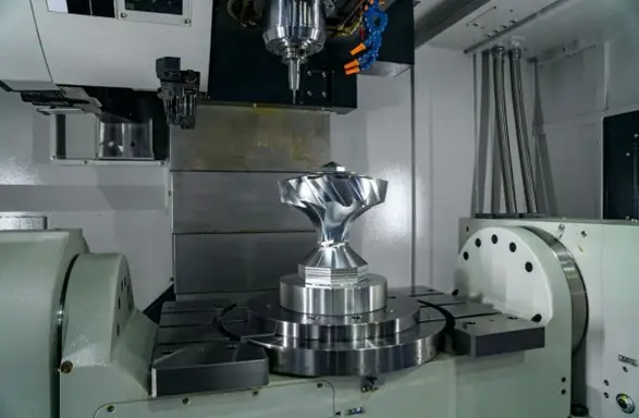
Both approaches use three linear axes together with two rotary axes, but they use those rotary axes differently. In 3+2 machining, the rotary axes position the workpiece or tool at a selected angle, then remain fixed while cutting occurs. This is often called indexed machining. In simultaneous 5-axis machining, linear and rotary movements can be coordinated continuously during the toolpath.
That distinction matters more than the machine label. A part may have several angled faces yet remain well suited to indexed orientations. Conversely, a feature may occupy only one area of a part but require simultaneous motion because its tool contact, clearance, or intended surface changes continuously. The drawing and CAD geometry should establish the needed motion, rather than an assumption that more axes automatically improve every part.
- Ask whether the cutting orientation is constant within each functional feature.
- Separate angled prismatic features from continuously varying sculpted surfaces.
- Identify where holder clearance, not feature angle alone, drives the process choice.
Where Indexed Orientations Work Well
3+2 machining is commonly a strong candidate for parts built from planes, pockets, holes, bosses, and features placed on several fixed angular faces. After indexing, the tool can approach a local face with familiar milling motions. This can make toolpath review, workholding concepts, and in-process measurement more direct, especially when the feature geometry does not demand changing tool tilt during the cut.
The value is not merely simpler programming. A fixed orientation can give a clear relationship between a local machining plane and the intended feature. That can help when a drawing defines depths, hole axes, profile zones, or positional requirements from established datums. It does not remove the need to control rotary positioning, fixture location, runout, tool reach, and accumulated variation between orientations.
Indexed machining should not be selected solely because a part appears block-like. Deep cavities, inclined walls, blended transitions, and obstruction from neighboring geometry can make a nominally prismatic part difficult to reach. Review the entire tool assembly envelope, including holder and shank clearance, against the finished model and any permitted stock condition.
- Useful starting case: fixed-angle faces with features normal to each face.
- Confirm whether repeated index positions can preserve the intended datum scheme.
- Check probing and inspection access after all material-removal stages.
When Continuous Motion Earns Its Place
Simultaneous 5-axis machining becomes relevant when a cutter must change orientation while traversing the surface. Typical drivers include compound-curvature surfaces, blended forms, narrow regions with changing access, and walls where a controlled tool attitude may reduce interference. Continuous motion can also support a shorter effective cutting condition in some geometries, but the result depends on the cutter, material grade, toolpath strategy, clamping condition, and agreed surface requirement.
Surface appearance deserves precise language. A changing tool orientation may help maintain a more favorable contact pattern on a complex surface, yet it is not a blanket finish guarantee. Tool marks, scallop character, cusps, blend boundaries, and witness areas depend on the specified finish, tool geometry, step-over strategy, stock consistency, machine behavior, and any subsequent finishing operation. Define where surface quality is functionally important and how it will be evaluated.
Continuous paths introduce their own planning burden. Rotary travel limits, singularity avoidance, collision checks, post-processing, feed behavior, and verification all affect feasibility. For that reason, a request for simultaneous motion should identify the exact surfaces or features that require it. A blanket instruction can obscure whether only a small region needs coordinated motion while the rest can use indexed or conventional operations.
- Mark continuous freeform surfaces separately from surrounding noncritical stock removal.
- State whether visual texture, profile conformance, sealing behavior, or aerodynamic function controls the surface requirement.
- Include allowed witness zones and blending limits when appearance or contact is important.
Geometry, Access, and Tool Reach
Part geometry should be evaluated as an access problem before it is evaluated as an axis-count problem. The relevant questions are whether the cutting edge can reach the finished region, whether the full tool assembly clears adjacent material, whether sufficient tool stiffness remains at the required reach, and whether a practical approach direction exists. These questions apply to both strategies, though continuous tool orientation can create additional options on changing-angle geometry.
Internal corners and deep walls often expose the limits of an early process assumption. A small cutter may enter a region but still lack rigidity, leave undesirable corner radii, or create excessive cycle time. A long tool may clear a wall but become sensitive to deflection. These are engineering tradeoffs to resolve from the final geometry, material grade, minimum wall condition, stock form, and tolerance framework—not universal design rules.
Designers can improve the review by identifying functional surfaces and allowing nonfunctional regions to support access where appropriate. If a feature requires a specific corner condition, surface blend, or local radius, show it explicitly. If an area may be relieved, blended, or left with a defined machining witness, that permission should be documented in the drawing or engineering agreement.
- Share the complete assembly model when mating clearances affect the finished envelope.
- Distinguish cosmetic surfaces from datum, sealing, bearing, or flow-critical surfaces.
- Show stock model and any pre-machined conditions that affect cutter access.
Datums Carry Through Manufacturing
A robust machining decision starts with the datum structure, not a preferred toolpath. Functional datums should locate the part in a way that corresponds to assembly and inspection. When features are machined from multiple indexed orientations, the manufacturing plan must maintain a defensible relationship to those datums. When a continuous surface is machined, the inspection strategy must similarly establish how the surface is aligned and assessed.
The controlled drawing should state dimensions, geometric tolerances, datum references, surface requirements, and revision status. A 3D model is valuable for geometry, but it may not communicate all acceptance conditions unless a model-based definition and its governing rules are agreed. Ambiguous blends, unspecified edge treatment, disconnected dimensions, and informal tolerance notes can create more risk than the selected axis strategy.
Inspection handoff should be planned early for surfaces that are difficult to probe or align. Define the measurement method where necessary, including datum simulation, sample density or scan coverage where applicable, reporting requirements, and whether measurement occurs before or after coating, heat treatment, or other specified operations. The applicable standard, drawing, and engineering agreement control acceptance.
- Identify the primary, secondary, and tertiary datums for finished-part acceptance.
- State the required inspection state: as-machined, after finishing, or both.
- Flag features whose verification needs special alignment, access, or reporting.
Compare the Process Tradeoffs
Neither method is inherently the lower-risk or lower-cost route. Indexed machining may reduce the complexity of certain programs and make fixed-face features easier to organize, but it can require multiple orientations and careful handling of transitions. Simultaneous machining may consolidate access to difficult surfaces or avoid some repositioning, while increasing the need for path verification and collision management. The practical outcome is specific to the part and process plan.
Quote evaluation should account for more than spindle time. Workholding complexity, stock preparation, tool selection, programming effort, verification, material behavior, inspection burden, secondary operations, and revision stability can all matter. A nominally simple feature may become expensive because it is hard to hold or measure; a complex shape may be manageable when its datum scheme and access are clear. Compare proposed approaches against the actual acceptance criteria.
| Decision factor | 3+2 machining | Simultaneous 5-axis machining | What should control the choice |
|---|---|---|---|
| Feature orientation | Fixed cutting angles after indexing | Tool orientation can change during cutting | Whether each feature has a stable, clear approach direction |
| Surface character | Well suited to planar and fixed-angle forms | Relevant to continuously changing forms | Specified geometry, surface intent, and permitted witness areas |
| Process planning | Often organized around discrete orientations | Requires coordinated rotary and linear path planning | Verified process plan, collision clearance, and machine travel |
| Inspection handoff | May align naturally with individual faces | May need explicit complex-surface alignment and coverage | Drawing datums, governing standard, and agreed measurement method |
| Quotation inputs | Depends on setups, fixture concept, and feature count | Depends on toolpath scope, reach, verification, and surface extent | Complete technical package rather than axis count alone |
Prepare a Better Quotation Package
A well-prepared quotation package lets manufacturing review the real decision instead of inferring requirements from a partial model. Supply the current native or neutral CAD model, controlled drawing, revision identifier, requested quantity, and material grade. Identify the intended stock form if it matters, along with any customer-supplied condition, pre-machining, heat-treatment state, coating, or finishing sequence that affects geometry or inspection.
Call out the features that make the decision sensitive: compound surfaces, narrow clearance zones, deep cavities, critical hole axes, appearance-controlled areas, and mating interfaces. Describe whether alternate process routes may be proposed, and separate mandatory requirements from preferences. If a specific machining mode is required by an external specification, cite that controlling requirement. Otherwise, invite a process recommendation supported by the part’s technical constraints.
Before release, confirm that the model and drawing agree, dimensions have units, datum references are complete, and any general notes have a governing standard. Resolve incomplete tolerances, undefined edge conditions, ambiguous threads, and unclear surface calls before requesting price or schedule. This reduces avoidable review cycles and produces a more meaningful comparison of indexed and continuous approaches.
- CAD model and controlled drawing with matching revision status.
- Material grade, stock condition, quantity, and required process sequence.
- Functional datums, tolerances, surface requirements, and inspection documentation needs.
- Explicitly marked regions that may require continuous tool orientation or special clearance review.
Questions engineers ask
Can a part use both 3+2 and simultaneous 5-axis machining?
Yes. A process plan may use indexed orientations for accessible fixed-angle features and reserve continuous coordinated motion for a specific changing-angle surface or clearance-limited region. The drawing, geometry, material grade, and agreed process plan determine whether that combination is appropriate.
Does simultaneous 5-axis machining automatically produce a better surface finish?
No. It can provide useful tool-orientation options on certain geometry, but finish depends on the specified requirement, cutter geometry, toolpath, material condition, clamping, stock consistency, and subsequent operations. Define the functional surface and its acceptance method rather than relying on the machining label.
What information is most important before requesting a quote?
Provide the current CAD model and controlled drawing, material grade, quantity, stock or supplied-part condition, finish sequence, functional datums, tolerances, surface requirements, and inspection needs. Highlight compound surfaces, restricted access, and any specification that controls the required machining method.
References and further reading
These resources explain related design and manufacturing principles. Project limits, acceptance criteria and process choices must be agreed against the current drawing.
Publication note: this article is general design guidance, not a material specification, a certified inspection report or a guarantee of process capability.
Turn the drawing into a clear manufacturing brief.
Share the current drawing, material, finish and inspection requirements for a project-specific discussion.