
Engineering article
How Setup Count Affects CNC Machining Cost
Setup count is a practical way to find hidden machining cost before requesting a quote. Each new orientation can add workholding, datum transfer, program verification, and inspection effort. The goal is not to force every feature into one operation, but to separate necessary reorientation from design-driven repositioning and communicate the intended manufacturing logic clearly.
On this page
Setup count is more than clamping
In CNC machining, a setup is the controlled condition in which a part is located, supported, clamped, and machined from an established coordinate reference. It is often described casually as putting a part in a machine, but the practical scope is wider. The setup includes selecting contact surfaces, controlling movement, establishing work offsets, proving tool access, and confirming that the part can remain stable while material is removed.
A new setup can be required when a feature cannot be reached from the current orientation, when the part must be turned over, or when a different operation needs a different holding method. The cost effect comes from the additional preparation and verification surrounding the cut, not simply from the fact that the part changes hands. This is why two parts with similar volume and material can have very different machining effort.
- Treat each orientation as a manufacturing decision with its own datum, workholding, access, and verification needs.
- Distinguish a deliberate process change from an accidental consequence of scattered feature directions.
Where repositioning enters the process
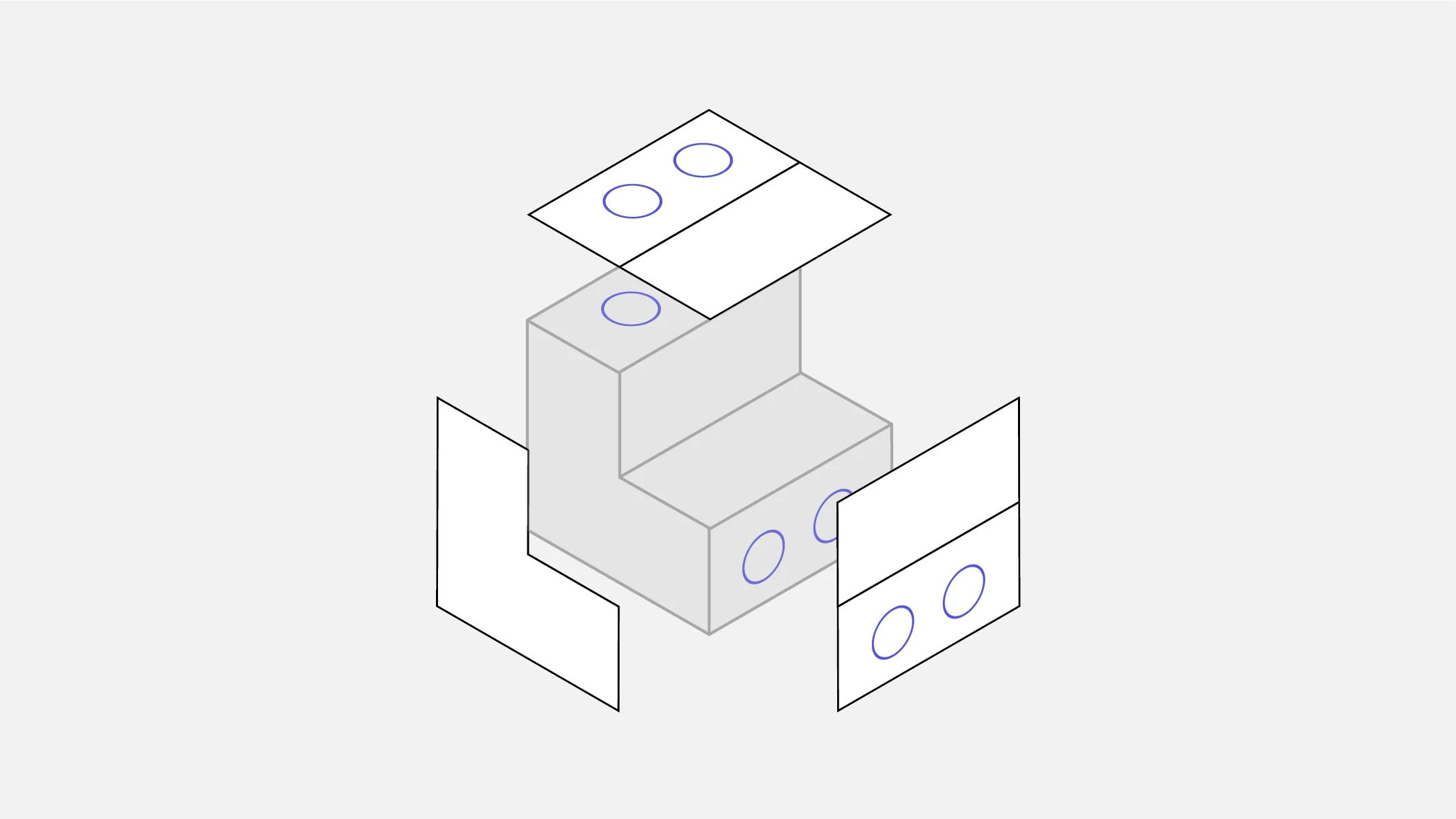
A prismatic component may begin with broad, flat faces that provide reliable support. Pockets, holes, and profiles on accessible faces can often be related to that initial reference. Repositioning becomes more likely when features appear on several sides, when holes meet at compound angles, or when the final geometry removes the surfaces that would otherwise support the part. Thin walls and interrupted clamping areas can also change what is practical.
Some repositioning is valuable. Turning a part may provide direct tool access, improve rigidity, or make a critical feature easier to inspect from its functional datum. Trying to avoid that turn at all costs can create an awkward holding arrangement or make the process less controllable. The useful question is whether the next orientation produces a required capability or merely compensates for an avoidable feature layout.
- Side holes may need a new orientation when they cannot be reached with the selected tool path.
- Features on opposite faces can require a datum transfer after the part is turned.
- Late-stage operations may need dedicated support when earlier machining has reduced stiffness.
Design around datum families
The clearest opportunity is usually not reducing the absolute number of faces with features; it is creating coherent datum families. Features that must function together should be dimensioned from the surfaces or axes that govern their real assembly relationship. When several features share one stable reference, the manufacturing and inspection plan has a stronger basis for keeping their relationships controlled without repeatedly re-establishing unrelated origins.
A drawing can unintentionally increase setup complexity when dimensions chain across faces that have no functional relationship, or when every feature is located from a different exterior edge. That pattern can force repeated transfers between references. Establishing primary, secondary, and tertiary datums where appropriate helps communicate what matters, while leaving the process planner room to choose safe intermediate references and workholding.
For a revision that moves a threaded port, adds a side slot, or changes an angled interface, review the feature against the existing datum family. If it belongs to a different manufacturing direction, ask whether it can be relocated, reoriented, or combined with a neighboring feature. The answer should follow function, assembly clearance, material behavior, and the drawing requirements—not a blanket rule about minimizing setups.
- Locate mating features from functional datums rather than convenient drawing edges.
- Keep related hole patterns on compatible faces when the product design permits it.
- Review late design additions separately; they often create a new orientation by themselves.
Access and workholding set the limit
Tool access determines whether a nominally simple feature can be machined in a current orientation. Cutter diameter, reach, holder clearance, corner form, and approach direction can all matter. A cavity may be open from one side yet still demand a different approach because a toolholder would collide with surrounding geometry. Likewise, an undercut or an oblique feature may call for a specialized process plan rather than a straightforward re-clamp.
Workholding is the other limit. Clamping must resist cutting forces without distorting the feature being controlled. A component with a convenient block-like starting form may be easy to secure early, then difficult to hold after contouring, thinning, or opening large pockets. Designers can help by preserving temporary holding land where it is acceptable, avoiding fragile unsupported tabs, and discussing whether a sacrificial area can be removed later.
Do not specify a holding strategy on the drawing unless it is functionally required and agreed with engineering. Instead, convey surfaces that cannot be marked, surfaces that must remain cosmetically protected, and geometry that cannot tolerate clamping contact. Those constraints let the process plan account for workholding without implying that a particular fixture method is mandatory.
- Check both cutting-tool access and toolholder clearance.
- Flag surfaces that cannot accept clamp contact or witness marks.
- Consider the machining sequence when thin sections surround pockets or bores.
Tolerances travel across setups
Every time a part is repositioned, the process must relate the new orientation back to the intended datum structure. This does not mean a multi-setup part cannot meet demanding requirements. It means that relationships spanning orientations deserve explicit attention. A hole on one face, a pocket on another, and a bearing feature on a third may be individually straightforward while their mutual location is the governing manufacturing challenge.
The drawing should state the datum references, geometric controls, surface requirements, and any measurement conditions needed to judge acceptance. Material grade, applicable standard, and revision-controlled model or drawing should also be unambiguous. If a feature must be assessed after coating, heat treatment, assembly, or another downstream step, that condition belongs in the engineering agreement or controlled documentation.
Inspection planning should follow the same logic. A feature may be measured directly in one orientation, while a relationship across multiple faces may require fixturing, probing, or an agreed inspection method. Sending only a visual model leaves too much interpretation. A complete handoff helps distinguish a feature that simply looks difficult from one whose functional relationship genuinely requires additional control.
- Call out cross-face relationships explicitly when they govern function.
- Avoid letting general dimensions substitute for a needed datum scheme.
- State the inspection condition when the final condition differs from the machined condition.
Compare alternatives before quoting
Before a quote is requested, compare alternative layouts at the feature level. The comparison is qualitative because the result depends on material grade, part size, required tolerances, selected process plan, quantity, and the controlled drawing. It is still useful because it reveals where a small design change could remove an otherwise isolated orientation or simplify the transition between operations.
A compact part with most detail on adjacent faces may be easier to plan than a similar part whose critical features are distributed around all faces. However, combining features into one orientation is only sensible if the resulting tool access, structural function, and datum logic remain sound. The preferred choice is the one that protects the part’s functional intent with the least unnecessary handling complexity.
| Design condition | Likely setup implication | Design review question |
|---|---|---|
| Features share one primary face and datum family | May support machining and inspection from a common reference | Can related features remain dimensioned from the same functional datums? |
| One isolated side feature | May introduce a dedicated orientation or alternative access plan | Can the feature move, rotate, or join another feature group without affecting function? |
| Critical relationships span multiple faces | Requires deliberate datum transfer and inspection planning | Are the cross-face controls explicitly defined and necessary? |
| Final form removes easy clamping surfaces | May require intermediate support or sequencing changes | Can nonfunctional holding land remain until late in the process? |
Prepare a useful pre-quote package
A good request for quotation gives the reviewer enough information to identify setup-driving geometry early. Provide the current drawing and model, revision status, material grade, quantity context, required finish or secondary operations, and any applicable standards. Mark critical functional interfaces and explain which surfaces mate, seal, locate, or remain visible. This context makes it easier to evaluate whether an extra orientation protects a real requirement.
Then ask targeted questions. Which features create distinct machining directions? Which requirements drive special workholding or inspection? Are there layout alternatives that preserve function with fewer datum transfers? Is any tolerance or finish requirement incomplete? These questions produce a more useful discussion than asking only how to lower cost, because they link the response to a specific geometry and controlled requirement set.
For SUUXIANG, the practical editorial lesson is to make setup count visible during design review. It is a map of access, support, datum control, and verification decisions. When that map is understood before release, teams can remove needless repositioning while retaining the operations their part actually needs.
- Include revision-controlled drawings and models together.
- List material grade, quantity, finishing requirements, and applicable standards.
- Identify functional surfaces and cross-face relationships.
- Request feedback on setup-driving features before freezing the layout.
Questions engineers ask
Does fewer setups always mean lower CNC machining cost?
Not necessarily. Reducing a needed orientation can worsen tool access, clamping stability, datum control, or inspection. Compare process options against the drawing, material grade, required features, and engineering agreement rather than treating one setup count as universally preferable.
Which drawing details help identify avoidable repositioning?
Functional datums, geometric controls, material grade, surface requirements, secondary-process conditions, and clear revision status are especially useful. Also identify which surfaces mate or locate in assembly, because that clarifies whether a cross-face relationship is essential.
Can a side feature be redesigned to avoid another setup?
Sometimes. A change in feature location, direction, geometry, or relationship to nearby features may allow a more coherent machining approach. The change should be reviewed against product function, assembly needs, tool access, workholding, and the controlled drawing before it is adopted.
References and further reading
These resources explain related design and manufacturing principles. Project limits, acceptance criteria and process choices must be agreed against the current drawing.
Publication note: this article is general design guidance, not a material specification, a certified inspection report or a guarantee of process capability.
Turn the drawing into a clear manufacturing brief.
Share the current drawing, material, finish and inspection requirements for a project-specific discussion.