
Threaded Mold Core Inserts, Built From Your Drawing
DFM-led machining, EDM, grinding, and inspection for custom threaded mold core inserts with critical dimensions and revision control reviewed before production.
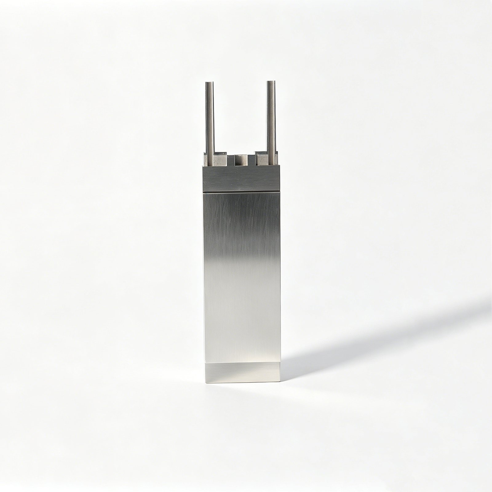
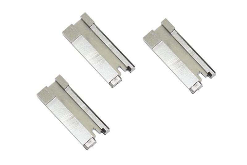
Representative Threaded Mold Core Insert Components








Related Configurable Component Families






Why Engineering Teams Choose Our Process
Threaded mold core inserts are planned from the drawing through machining, EDM, grinding, inspection, and controlled revision handling.
DFM Before Quotation
We review critical dimensions, datum strategy, thread geometry, tool access, and process risks before production commitments are made.
Process Route Planning
CNC machining, EDM, grinding, and fitting are selected around feature access, material condition, surface requirements, and inspection priorities.
Critical Feature Control
Threaded mold core inserts receive focused planning for thread form, concentricity, mating interfaces, and dimensions identified as critical to quality.
EDM and Grinding Strategy
Where geometry requires it, electrode strategy, wire paths, and grinding stock are considered before final feature finishing begins.
Inspection Matched to Requirements
Inspection methods and final documentation are aligned with the drawing, agreed quality plan, and specified reporting requirements.
Visible Revision Control
Drawing updates, manufacturing changes, and delivery coordination remain traceable throughout the project to reduce avoidable production ambiguity.
Threaded Core Inserts and Precision Tooling
Configurable, drawing-driven categories for mold components, connector tooling, and low-volume precision parts—reviewed against manufacturing, inspection, and delivery requirements before commitment.

CNC Machining Services
Precision CNC machining services for drawing-based parts requiring controlled features, datums, and inspection planning. Process routes may combine milling, turning, EDM, grinding, and fitting according to geometry, material condition, critical dimensions, and documented quality requirements.
Upload a Drawing
CNC Milling
Custom CNC milling services for plates, inserts, mold details, and prismatic custom parts. Drawing review considers tool access, datum setup, pocket geometry, corner conditions, machining allowance, surface requirements, and features that may require EDM or finishing operations.
Upload a Drawing
CNC Turning
Precision CNC turning services for threaded cores, pins, sleeves, bushings, and rotational components. RFQ review should define thread form, datum relationships, runout, surface requirements, material condition, and whether secondary milling, EDM, grinding, or inspection is required.
Upload a Drawing
5-Axis Machining
5-axis CNC machining for contoured inserts, angled features, complex tool access, and multi-face parts where fewer setups may protect datum relationships. Feasibility depends on geometry, tooling reach, material, tolerances, surface requirements, and the approved inspection approach.
Upload a Drawing
Swiss & Micro Machining
Swiss machining and micro machining for small-diameter, elongated, or detail-intensive components where support, concentricity, and feature access influence the process route. Drawings should identify critical diameters, threads, cross features, material, quantity, and inspection priorities.
Upload a Drawing
Wire & Sinker EDM
Wire EDM and sinker EDM services for hardened features, sharp internal geometry, narrow slots, precision profiles, and forms inaccessible to conventional cutting tools. Electrode strategy, wire path, recast-layer considerations, finish requirements, and subsequent grinding or fitting should be reviewed.
Upload a Drawing
Precision Grinding
Precision surface and profile grinding for controlled flatness, parallelism, profiles, dimensions, and finishing stock after machining or heat treatment. Drawings should establish datums, grinding allowance, material condition, critical relationships, surface requirements, and inspection method.
Upload a Drawing
Mold Core & Cavity Inserts
Precision mold core and cavity inserts produced as configurable, drawing-defined components rather than stock items. Review covers parting-line geometry, shutoffs, cooling or vent features, steel and heat-treatment requirements, machining access, EDM strategy, fitting interfaces, and critical dimensions.
Upload a Drawing
Ejector & Ejection Components
Ejector pins, sleeves, and ejection components manufactured to drawing requirements for motion, clearance, alignment, and wear considerations. Define diameters, lengths, head or sleeve geometry, material and hardness requirements, surface condition, mating relationships, and inspection expectations.
Upload a Drawing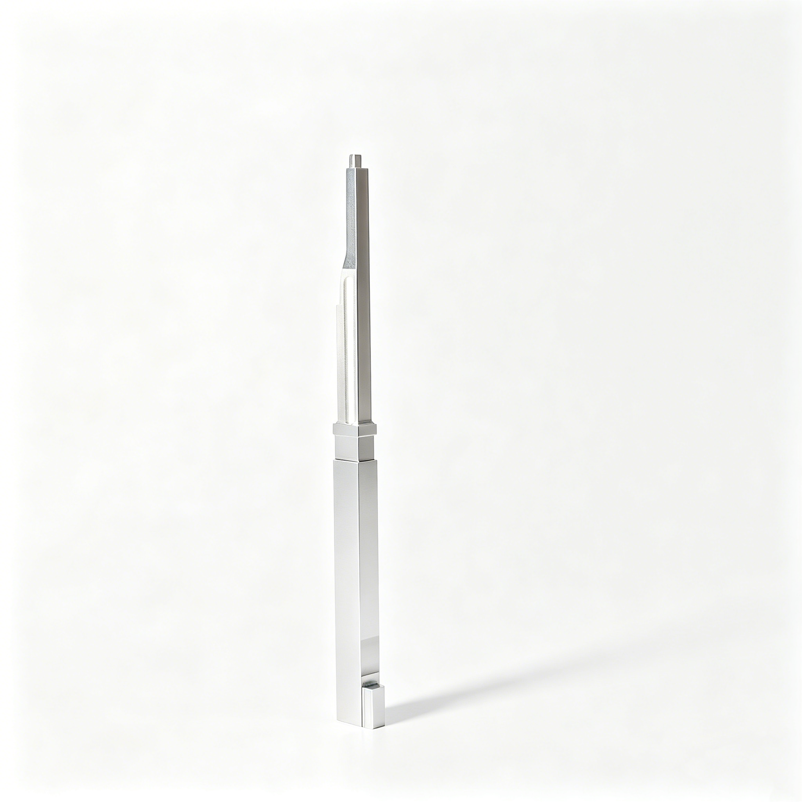
Core Pins, Guide & Locating Components
Core pins, guide pins, and locating components made to support repeatable molding alignment and feature formation. A practical review addresses mounting details, fit class, concentricity, datum relationships, material condition, wear surfaces, mating components, and any grinding or heat-treatment sequence.
Upload a Drawing
Slides, Lifters, Gates & Mold Accessories
Mold slides, lifters, gates, and accessories configured from approved drawings and assembly interfaces. Manufacturing planning considers travel or shutoff geometry, locking and locating features, wear surfaces, cooling or vent details, machining access, fitting needs, and critical functional relationships.
Upload a Drawing
Connector Mold Components
Precision connector mold components for fine-pitch, multi-cavity, and interface-sensitive tooling applications. Drawings should identify pin or insert geometry, positional tolerances, datum scheme, material and heat treatment, EDM needs, mating context, surface requirements, and inspection documentation.
Upload a Drawing
Stamping Die Components
Precision stamping die components for cutting, forming, guiding, and locating functions within drawing-defined die assemblies. Process review considers steel selection, hardness, clearance-sensitive features, wire EDM profiles, grinding stock, edge condition, mating relationships, and dimensional verification.
Upload a Drawing
Injection, MIM, CIM & Overmolding Tooling
Tooling and component work supporting injection molding, metal injection molding, ceramic injection molding, and overmolding within verified production scope. Inquiry packages should define the process context, part geometry, material requirements, interfaces, critical features, tooling function, and required inspection evidence.
Upload a Drawing
Machining Materials
CNC machining materials selected from customer requirements and manufacturing feasibility, including machinability, stability, wear resistance, corrosion exposure, and heat-treatment sequence. Submit the specified grade, condition, material standard, application context, and any traceability or certification requirements with the RFQ.
Upload a Drawing
Surface Finishes & Heat Treatment
Surface finishing and heat treatment planned around function, dimensional risk, corrosion or wear requirements, and post-process inspection. Define the required finish or treatment, applicable standard, coverage areas, masking needs, hardness target where relevant, and dimensional features affected by processing.
Upload a Drawing
Quality, Metrology & Documentation
Precision inspection, metrology, and quality documentation aligned to the order and approved inspection plan. Specify critical dimensions, datums, measurement method expectations, sampling or reporting needs, revision status, material documentation, and any customer-defined traceability requirements before production.
Upload a Drawing
Prototyping & Low-Volume Production
Rapid prototyping and low-volume manufacturing for drawing-based parts that need practical DFM review before release. Provide 2D drawings, 3D models when available, material, quantity, critical dimensions, surface and heat-treatment needs, delivery target, and inspection requirements.
Upload a DrawingMaterials for Threaded Mold Core Inserts

Tool Steel
A practical choice for general-purpose threaded core inserts where balanced machinability and wear resistance are needed. Confirm the required grade, hardness range, thread finish, and heat-treatment sequence against molding conditions and critical dimensions.

Pre-Hardened Steel
Suitable when a stable, production-oriented steel condition is preferred and post-machining heat treatment may be limited. Review thread geometry, grinding allowance, surface requirements, and expected wear before defining the final material condition.

Stainless Steel
Consider for mold environments where corrosion resistance matters, including humid storage or resins that demand additional protection. Grade selection, hardness, surface finish, and any coating requirement should be verified from the application and drawing.

High-Speed Steel
Used for demanding threaded features that require stronger wear resistance under repeated molding cycles. Its machining and heat-treatment route need early review to protect critical threads, datums, surface finish, and inspection requirements.

Copper Alloy
Useful for localized thermal-management applications where heat transfer is a key design consideration. Because wear resistance differs from hardened steels, confirm thread loading, insert support, machining approach, and compatibility with the mold assembly.
Threaded Mold Core Inserts: Machining and Finishing Processes


Wire EDM
Wire EDM can produce precise external profiles, narrow features, and hard-material contours where conventional cutter access is limited. Wire-path planning considers datum transfer, corner conditions, stock state, and the dimensional requirements of mating mold components.

Sinker EDM
Sinker EDM supports internal details, deep ribs, and feature geometry that requires a controlled electrode strategy. Electrode design, burn allowance, surface expectations, and subsequent finishing requirements are reviewed against the approved drawing.


Fitting Review
Fitting checks how threaded mold core inserts interface with adjacent cores, cavities, slides, or locating components. The review focuses on assembly access, seating surfaces, engagement conditions, clearance risks, and drawing-defined functional relationships before delivery.

Inspection Planning
Inspection planning aligns measured features with drawing callouts, critical dimensions, datums, and reporting requirements. Results are documented according to the agreed inspection plan, helping maintain traceability across revisions, production stages, and final shipment.
Threaded Mold Core Inserts and Supporting Features

Threaded Interfaces
Internal or external threads can be planned around engagement length, runout, relief, and inspection access. Provide the mating-part specification and thread callout so SUUXIANG can review the machining route before quotation.

Locating Features
Dowel holes, shoulders, register diameters, and datum faces help establish repeatable positioning during mold assembly. Their relationship to critical dimensions should be defined from functional datums, not treated as isolated features.

Guide Components
Guide pins, bushings, and related locating elements can be specified with fit, hardness, lubrication, and replacement considerations. Share the mating-component details to assess clearance, assembly sequence, and service access.

Anti-Rotation Details
Flats, keyways, drive slots, and alignment features can prevent insert rotation or establish installation orientation. Their geometry should account for torque transfer, machining access, stress concentration, and inspection requirements.

Custom Mating Fits
When threaded mold core inserts must mate with existing cavities, holders, or connector tooling, submit the relevant interface drawings or models. SUUXIANG can review fit intent, datum transfer, tolerance stack, and revision-controlled requirements.
Threaded Mold Core Inserts Manufacturing
SUUXIANG is the international-facing brand of Dongguan SuuXiang Precision Mold Co., Ltd., established in 2010 in Chang’an Town, Dongguan, China. We support global engineering and sourcing teams with drawing-driven precision manufacturing for threaded mold core inserts, mold components, connector tooling, and custom CNC-machined parts.
Our process planning brings together CNC milling and turning, multi-axis machining, EDM, precision grinding, fitting, and inspection. Before quotation or production commitments, we review drawings, critical dimensions, datum strategy, thread requirements, machining access, heat-treatment sequence, and inspection expectations with the project team.
What distinguishes SUUXIANG is disciplined coordination between design intent and verified production work. We keep revision information, process decisions, and inspection requirements visible throughout the job, helping buyers assess manufacturability and prepare the material, quantity, quality, delivery, and documentation details needed for a productive RFQ.

Threaded Mold Core Inserts: Critical Feature Control
Drawing and DFM Review
Before quotation, SUUXIANG reviews threaded mold core insert drawings for critical dimensions, datum logic, thread specification, tool access, material condition, and surface requirements. The review identifies manufacturing questions early so the agreed process route and inspection priorities reflect the actual application.
- Confirm thread form, class, engagement, and blind-hole requirements
- Identify critical-to-quality dimensions and functional datums
- Review access limits for milling, drilling, EDM, and grinding
- Align revision status, material, quantity, and delivery requirements

EDM Strategy for Threads
Where conventional cutting cannot reliably reach a threaded feature or surrounding geometry, SUUXIANG assesses wire-EDM or sinker-EDM requirements alongside electrode design and finishing needs. The strategy considers feature geometry, tool clearance, recast-layer considerations, and downstream polishing or fitting work.
- Assess EDM suitability against feature geometry and access
- Plan electrode or wire paths around critical surfaces
- Define finishing needs after EDM where required
- Keep EDM decisions visible in the production route

Grinding Allowance Control
For threaded mold core inserts with precision locating faces, diameters, or shutoff-related surfaces, grinding stock must be planned before hardening and intermediate machining. SUUXIANG coordinates allowance, datum retention, and machining sequence to support stable final geometry rather than treating grinding as a last-minute correction.
- Reserve appropriate stock for final grinding operations
- Protect functional datums through heat-treatment sequencing
- Coordinate turned, milled, EDM, and ground surfaces
- Review mating conditions when fitting information is available

Inspection and Project Coordination
Inspection planning begins with the drawing and agreed critical features. SUUXIANG aligns measurement methods, reporting expectations, revision control, and delivery coordination for threaded mold core inserts so final documentation corresponds to the order and verified inspection plan.
- Define inspection methods for critical dimensions and threads
- Clarify report format and documentation requirements
- Maintain revision visibility through project coordination
- Confirm delivery information against the approved order

SUUXIANG vs. Typical Quote-Only Suppliers
For threaded mold core inserts, the comparison starts with drawing comprehension, critical features, and controlled production evidence.
← Swipe left or right to view →
Threaded Mold Core Inserts Production Workflow
A controlled process that keeps DFM decisions, critical dimensions, revision status and inspection requirements visible from review through delivery coordination.
Review Drawings and Requirements
We review drawings, models, material, quantity, datums, threads, surface requirements, critical dimensions, inspection needs and target delivery date before committing to a process route.
Plan Manufacturing and DFM
The team confirms machining access, tolerance stack considerations, heat-treatment sequence, EDM or wire-path needs, grinding stock and inspection approach for the approved revision.
Machine Threaded Core Features
CNC milling, turning, multi-axis machining and suitable micro-machining operations produce threaded mold core inserts while preserving required allowances for downstream processes.
Apply EDM and Grinding
Wire EDM, sinker EDM and precision grinding are selected where geometry, hardened material, surface condition or dimensional control calls for a complementary finishing route.
Fit and Inspect Components
Fitting and inspection follow the agreed plan, with critical dimensions, thread condition, datum-based checks and required reporting aligned to the order requirements.
Pack and Coordinate Delivery
Approved parts are packed for shipment, with revision and delivery information coordinated against the order so receiving teams can match components to project documentation.
Start Your Threaded Mold Core Inserts RFQ
Provide the drawing, requirements, and inspection priorities needed for a practical DFM and quotation review.
Share Your Drawings
Send the 2D drawing and, where available, 3D model for threaded mold core inserts, including revision status, datums, critical dimensions, and thread specifications.
Define Material Requirements
Specify material, heat-treatment condition, quantity, application context, and any mating-component details that affect tool access, machining strategy, or feature design.
Identify Quality Priorities
Highlight tolerance, surface, thread, and inspection requirements, along with reporting expectations and acceptance criteria, so the inspection plan matches the order.
Confirm Delivery Targets
Provide your target delivery date and project constraints. SUUXIANG reviews the drawing, DFM considerations, process route, and feasible coordination requirements before commitment.
Threaded Mold Core Insert Project Scenarios
Threaded Mold Core Inserts: Customer Project Feedback
SUUXIANG’s drawing review flagged two thread-relief and grinding-access risks before release. The revised core inserts matched our approved inspection points, and the first article review closed with 18 of 18 reported critical dimensions accepted.
For a 24-piece threaded mold core insert order, the team kept revision status clear through machining and inspection. Their dimensional report let our supplier-quality group complete incoming review without requesting an additional measurement cycle.
Our RFQ involved 12 insert variants with different thread forms and heat-treatment sequencing. SUUXIANG separated the EDM, grinding, and inspection considerations early, helping us approve the process route before production rather than resolve issues at tryout.
Threaded Mold Core Inserts FAQ
Practical RFQ, quality, delivery, and project-control questions for drawing-driven precision component sourcing.
What information should I send for threaded mold core inserts quotation?
Is there a minimum order quantity for threaded mold core inserts?
Can SUUXIANG make a sample before production of threaded mold core inserts?
What affects the lead time for a custom threaded mold core insert?
Can I request an inspection report with my order?
How are threaded mold core inserts shipped internationally?
What payment information is needed to start a custom manufacturing order?
How does SUUXIANG handle drawings and intellectual property?
Complete Buyer’s Guide to threaded mold core inserts
Use this decision framework to specify threaded mold core inserts, compare construction and material options, evaluate qualified suppliers, control tooling risk, and avoid sourcing mistakes that compromise molded-part performance.
1. What Are threaded mold core inserts?
One threaded mold core insert is a precision, replaceable tooling element whose machined thread profile forms an internal or external thread in a molded part. It is mold tooling, not a component intended to remain in the finished product.
One molding cycle fills plastic around or against the threaded form, then requires a controlled release after cooling. Unscrewing, collapsible, stripping, or removable-core actions may be required; straight ejection can damage a thread that remains mechanically locked to the core.
Two items are commonly confused with this tooling: a molded-in metal fastener insert remains embedded in the plastic, while a complete mold core is the larger assembly that may carry one or more inserts. The buyer’s requirement is repeatable thread form and reliable part release without scuffing, cracking, deformation, or cycle-to-cycle variation.
2. Evolution of Thread-Forming Mold Tooling
One-piece fixed cores were practical when an external thread could strip from the steel without damaging the molded feature. Hand-loaded cores and inserts then made short runs and design changes feasible, but their repeatability depended on loading position, retention, and operator handling.
Two interchangeable insert interfaces changed the procurement equation: a worn thread-forming element could be replaced without remachining the full mold block. Buyers should request the insert datum, retention method, revision marking, spare quantity, and the inspection method for pitch, major or minor diameter, and runout.
Three release routes now guide program selection: fixed or hand-loaded tooling for limited volumes, unscrewing mechanisms for recurring threaded production, and collapsible cores for internal threads that cannot strip conventionally. Automated thread release can improve cycle-to-cycle consistency and reduce handling, while resin shrinkage, reinforcement, thread depth, and expected maintenance must be reviewed before selecting the mechanism.
3. Types of threaded mold core inserts
Six architectures cover most internal-thread releases. Select from the drawing’s thread depth, undercut, pitch, access direction, annual volume, and acceptable tool-maintenance burden before freezing the mold concept.
| Type | Thread Geometry | Release | Volume Fit | Advantage And Limitation |
|---|---|---|---|---|
| Fixed threaded core | Shallow, strip-capable | Ejection/stripping | Low to medium | Simple; limited by stripping force |
| Hand-loaded insert | Deep or inaccessible | Manual removal | Prototype to low | Low tool cost; cycle labor |
| Unscrewing core | Full-depth internal | Rotary unscrewing | Medium to high | Clean release; drive complexity |
| Collapsible core | Undercut internal | Core collapses | Medium | Compact; wear-sensitive mechanism |
| Split core | Large or interrupted thread | Segments retract | Low to medium | Flexible geometry; complex alignment |
| Modular insert | Revision-prone threads | Insert exchange | Any, with spares | Serviceable; requires datum control |
Fixed And Hand-Loaded Cores
Fixed cores suit shallow, straight threads when stripping is feasible. Hand-loaded inserts release with the part and suit low-volume or difficult-access threads.
Automatic Release Systems
Unscrewing cores suit full-depth internal threads requiring axial rotation. Collapsible and split cores create clearance for undercuts, but add moving interfaces and maintenance points.
Modular Insert Strategy
Interchangeable modules isolate thread-forming features from the base tool. They support revisions and service replacement, provided datums, retention, and spare-insert control are defined.
4. Materials for threaded mold core inserts
Material selection for threaded mold core inserts determines thread life under molding heat, resin abrasion, and repeated demolding. Specify resin, finish, projected cycles, and maintenance access during drawing review.
| Material | Hardness | Wear And Corrosion | Thermal Behavior | Coating Fit | Typical Use |
|---|---|---|---|---|---|
| Pre-hardened alloy steel | Often 28–40 HRC | Moderate wear; low corrosion | Moderate conduction | Often compatible after preparation | General resin, repairable tooling |
| Through-hardened tool steel | Grade and heat-treatment dependent | High wear; low corrosion | Moderate conduction | Common coating candidate | Abrasive or glass-filled resin |
| Stainless tool steel | Grade and heat-treatment dependent | Moderate-high wear; high corrosion | Moderate conduction | Grade-dependent | Corrosive resin, polished surfaces |
| Beryllium-free copper alloy | Usually lower than tool steel | Low thread wear resistance | High conductivity | Limited | Local cooling support |
Steel Selection By Duty
Pre-hardened alloy steel suits prototypes and moderate production. It machines and repairs readily.
Glass-filled resin requires a wear review. Set hardness against the selected grade.
Corrosion And Heat Management
Through-hardened tool steel addresses high-cycle, abrasive service. Leave grinding allowance before hardening.
Stainless grades address humid or corrosive molding. Copper-alloy, beryllium-free supports move heat away but should not form exposed thread flanks.
5. Custom threaded mold core inserts Design Features
Custom threaded mold core inserts should be defined from the drawing, mating part, and molding conditions. Early review fixes thread form, datum scheme, service interfaces, and replacement boundaries before machining begins.
Thread Geometry And Engagement
ISO, Unified, or customer-specific thread designation should state class, pitch, handedness, engagement length, lead-in, and acceptable crest and root condition.
0.5 mm pitch changes can materially affect tool access and release behavior; specify whether gauges, mating screws, or functional assembly define acceptance.
Interfaces And Service Features
2 datum references should locate the thread relative to shutoff, parting, or mating features. Specify cooling connections, vent locations, anti-rotation flats or keys, and which wear region must be replaceable.
1 replaceable nose or threaded sleeve can limit maintenance scope when resin abrasion or repeated assembly concentrates wear.
RFQ Data And DFM Tradeoffs
3D model, 2D drawing, resin grade, filler percentage, molding temperature, and mating-part details should accompany the RFQ. Identify cosmetic surfaces and critical sealing or thread dimensions.
Fine pitches, deep threads, blind holes, and undercuts can increase EDM, wire-path, cleaning, and inspection complexity. State allowable relief, vent marks, and surface-finish priorities so SUUXIANG can review a practical process route.
6. Quality Elements That Protect Thread Performance
Two geometry checks—concentricity to the mold-base datum and assembled runout—govern whether a threaded core turns and releases on its intended axis. Treat them as functional controls, not drawing decorations.
Geometry And Thread Gaging
100% thread-gage verification on agreed critical cores confirms pitch, major/minor diameter, and engagement before assembly. Excess runout or a nonconforming thread can cause sticking, cross-threading, stripping, and uneven flank wear.
Surface And Heat Control
Ra requirements, specified by the drawing, should cover thread flanks, root, lead-in, and sealing lands. Correct heat-treatment sequence, coating compatibility, and controlled edge breaks reduce galling, flash initiation, pickup, and premature wear.
Mold Interface And Records

Three interfaces require review: core-to-base fit, cooling path clearance, and venting near trapped air. Poor seating promotes flash; restricted cooling or venting can impair release and create inconsistent cycle times.
Each accepted part should retain revision-linked dimensional results, gage identity, inspection method, and disposition. SUUXIANG should align these records with the agreed inspection plan before shipment.
7. How to Choose a Threaded-Core Manufacturer
One qualified supplier turns the drawing into a documented process plan before quoting. Price comparisons are meaningful only after thread function, datums, material condition, and inspection evidence are aligned.
Review The DFM Response
One DFM response should identify critical threads, datum references, tool access, EDM or grinding needs, and unresolved assumptions.
Two RFQ questions matter: Which features drive risk, and what drawing changes or clarifications are required before release?
Verify Control Evidence
Three evidence streams should be requested: material identification, heat-treatment or coating records where specified, and the thread-metrology method.
Four checkpoints should be defined: incoming material, post-machining, post-EDM or grinding, and final inspection with revision traceability.
Test Delivery Discipline
One pilot order reveals whether the supplier can communicate revision changes, report in-process issues, and support fitting within a mold assembly.
Two RFQ questions expose maturity: What is the realistic lead-time basis, and how is a nonconformance contained, corrected, and documented?
8. Common threaded mold core inserts Buying Mistakes
Threaded mold core inserts are often purchased from incomplete drawings rather than a defined molding and maintenance scenario. A short pre-award review prevents expensive rework after tool assembly.
Separate Tooling From Part Inserts
Two components are commonly confused: the hardened tooling core that forms a thread and the metal insert retained in the molded part. This mismatch can produce an unusable quote; provide the assembly section, function, and mating-part context.
Define Thread And Release
Three drawing items need confirmation: thread standard and class, critical tolerance or datum, and release direction. Missing callouts invite incompatible gauges, interference, or an impractical unscrewing or collapse mechanism; review the thread section with the mold designer.
Compare Manufacturing Scope
Four inputs—resin, expected cycle demand, heat treatment, and finish—must be checked before selecting steel or a surface treatment. Unsupported finishes or unverified hardness can shorten service life; request process and inspection evidence.
Two quotations are comparable only when EDM, grinding, fitting, inspection reports, spares, and revision handling are aligned. Compare a line-by-line scope matrix before nomination.
9. Steps to Launch a Threaded-Core Tooling Program
A disciplined launch turns threaded mold core insert requirements into controlled decisions before metal is cut. SUUXIANG can align drawing review, process planning, inspection evidence, and revision communication to the approved order.
Freeze The Technical Package
Gate 1 requires the design owner to supply 2D drawings, 3D models, thread callouts, datums, material, heat treatment, quantity, and mating-part context.
Gate 2 records critical dimensions, surface requirements, application function, and revision level. Procurement and quality should confirm the inspection-report requirement before quotation.
- 2D drawing and native or neutral 3D model
- Thread specification and datum scheme
- Material, hardness, finish, and quantity
Close DFM And Quote
Gate 3 is a documented DFM review covering tool access, EDM or wire path, grinding stock, heat-treatment sequence, and measurable datums.
Gate 4 releases quotation only after engineering, sourcing, and quality agree on scope, exclusions, delivery target, and revision-controlled acceptance criteria.
- Confirm prototype versus recurring-production intent
- Identify customer-supplied gauges or mating samples
- Approve the controlled drawing revision
Validate Trials And Continuity
Gate 5 compares first-article results with the agreed inspection plan before mold-trial use. Trial feedback must identify thread engagement, release behavior, wear observations, and any drawing change.
Gate 6 approves production release after the responsible design, quality, and program stakeholders close deviations. For low-volume work, define spare-insert quantities, storage identification, and replacement revision rules early.
- First-article report and deviation record
- Mold-trial feedback and corrective action
- Approved spare-insert and traceability plan
10. Threaded Mold Core Inserts Pricing and Cost Drivers
Five quote lines should be separated: engineering review, machining, secondary processing, inspection, and expedited work. Combining them hides the cost effect of revision control, heat treatment, EDM, grinding, and reporting.
Two inserts with identical nominal threads can have different lifecycle cost when one requires tighter datum control or more frequent replacement. Compare the delivered insert, inspection evidence, mating performance, and replacement lead time—not unit price alone.
| Cost driver | Lower-cost route | Higher-cost route | Quote impact |
|---|---|---|---|
| Architecture | Straight, accessible core | Undercut or split-core geometry | More setups, electrodes, or fitting |
| Material and heat treatment | Pre-hardened material | Tool steel with controlled heat treatment | Secondary processing and grinding increase |
| Thread and finish | Coarse, standard thread | Fine thread, polished or EDM-critical form | Longer machining and verification |
| Quantity and inspection | Repeat quantity; dimensional checks | Prototype quantity; full report or special gauges | Setup spread improves; inspection adds cost |
| Lead time | Planned schedule | Expedited delivery | Capacity changes must be priced separately |
Upload Your Threaded Mold Core Inserts Drawing
Submit material, quantity, critical tolerances, surface requirements, inspection needs, and delivery target for a disciplined DFM and quotation review.