
FPC Connector Mold Inserts, From Drawing to Inspected Tooling
SUUXIANG reviews critical dimensions, then applies CNC machining, EDM, grinding and inspection for FPC connector mold inserts.
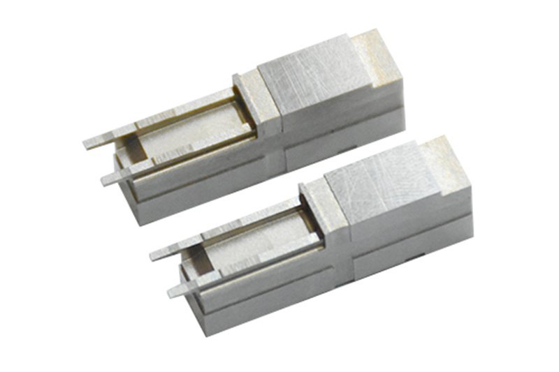
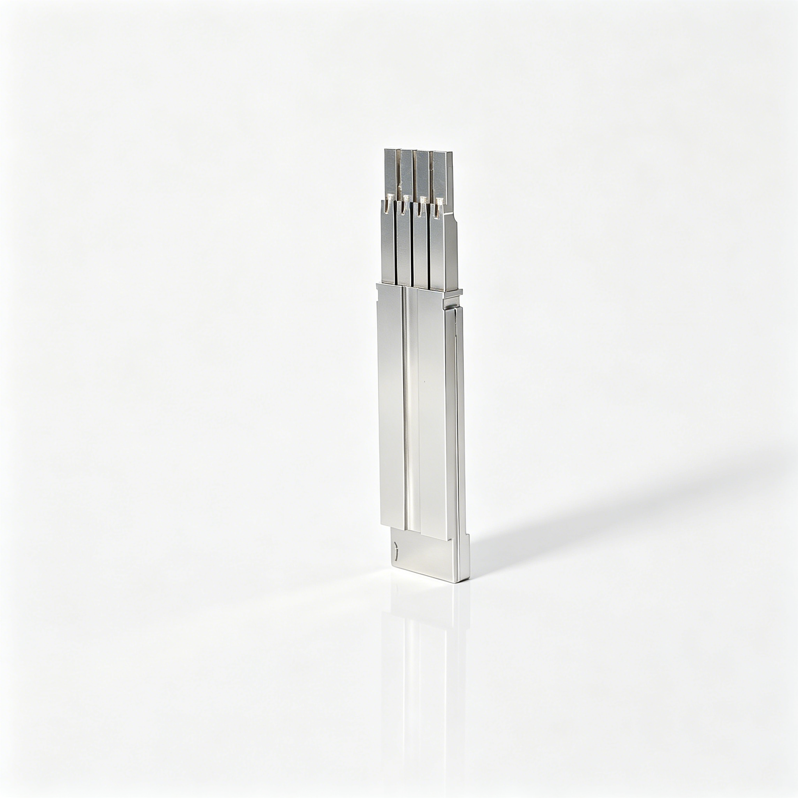
Representative FPC Connector Mold Insert Configurations












Related Configurable Components and RFQ Support









FPC Connector Mold Inserts: Engineering Advantages
A disciplined review path for turning connector-tooling drawings into controlled manufacturing and inspection plans.
Drawing Review First
We review drawings, models, materials, quantities, and application context before defining a quotation or production approach.
Critical Dimensions Defined
Critical dimensions, datums, surface requirements, and tolerance relationships are identified early to focus process and inspection planning.
Process Route Planning
CNC machining, EDM, grinding, fitting, and inspection are considered together around tool access, geometry, and finishing needs.
Revision Visibility
Drawing revisions and project information remain visible through coordination, helping teams align production with the current approved requirements.
Inspection Plan Alignment
Inspection methods and required documentation are discussed against the order, dimensional priorities, and agreed verification expectations.
FPC Connector Mold Component Families
Drawing-driven component families for connector tooling, mold construction, die work, and controlled low-volume production.

CNC Machining Services
Precision CNC machining services for drawing-based custom parts requiring planned milling, turning, EDM, grinding, fitting, and inspection routes. Review critical dimensions, datums, material requirements, and surface priorities before committing to a process plan.
Upload a Drawing
CNC Milling
Custom CNC milling services for prismatic mold and tooling components, including inserts, plates, slides, and fixture details. Tool access, internal radii, wall geometry, machining allowance, and datum relationships should be reviewed against the drawing.
Upload a Drawing
CNC Turning
Precision CNC turning services for rotational components such as pins, sleeves, bushings, shafts, and locating features. Quotations should account for diameter tolerances, concentricity, shoulder geometry, thread requirements, material condition, and inspection method.
Upload a Drawing
5-Axis Machining
5-axis CNC machining supports complex geometry where multiple faces, angled features, or compound contours benefit from fewer setups. The machining route depends on tool reach, clamping strategy, datum control, surface requirements, and remaining finishing operations.
Upload a Drawing
Swiss & Micro Machining
Swiss machining and micro machining support small, detailed turned parts with features that require stable workholding and deliberate inspection planning. Provide functional dimensions, mating context, material, quantity, and any critical surface or burr-control requirements.
Upload a Drawing
Wire & Sinker EDM
Wire EDM and sinker EDM services address profiles, narrow slots, internal corners, hardened materials, and difficult-to-reach mold features. Electrode strategy, wire path, flushing access, recast-layer expectations, and downstream polishing or grinding requirements require review.
Upload a Drawing
Precision Grinding
Precision surface and profile grinding is used where flatness, parallelism, profile control, or fine finishing is critical. Specify grinding stock, heat-treatment condition, datum surfaces, surface requirements, and the dimensions to be verified after grinding.
Upload a Drawing
Mold Core & Cavity Inserts
Precision mold core inserts and cavity inserts are configurable components produced from approved drawings and mold-function requirements. Their process route may combine CNC machining, EDM, grinding, fitting, and inspection based on parting geometry, material condition, cooling, and critical molding surfaces.
Upload a Drawing
Ejector & Ejection Components
Ejector pins, sleeves, and ejection components are drawing-driven mold details requiring attention to fit, stroke, guidance, lubrication, wear surfaces, and mating-hole conditions. Dimensions, material and heat-treatment requirements, and functional clearances should be defined before production.
Upload a Drawing
Core Pins, Guide & Locating Components
Core pins, guide pins, and locating components establish molding features and repeatable alignment within a tool. Evaluate working diameter, fit class, datum relationships, wear conditions, mounting method, material condition, and inspection requirements from the application drawing.
Upload a Drawing
Slides, Lifters, Gates & Mold Accessories
Mold slides, lifters, gates, and accessories are configurable tooling families that require functional review of travel, bearing surfaces, shutoffs, gating geometry, assembly interfaces, and service access. Manufacturing planning should reflect the intended mold sequence and mating components.
Upload a Drawing
Connector Mold Components
Precision connector mold components support tooling for detailed connector features where alignment, pin geometry, cavity relationships, and repeatable mating conditions matter. Drawings should identify critical-to-quality dimensions, datum scheme, material, finish, and applicable inspection evidence.
Upload a Drawing
Stamping Die Components
Precision stamping die components include drawing-based inserts, punches, guides, plates, and locating details for die assemblies. Process planning considers material condition, cutting or forming interfaces, clearance relationships, grinding allowance, heat treatment, and inspection of functional dimensions.
Upload a Drawing
Injection Mold Components for MIM, CIM & Overmolding
Injection, MIM, CIM, and overmolding tooling components are evaluated within verified production scope. A useful review includes material behavior, feature geometry, parting and shutoff requirements, feed or gate context, molding conditions, and the dimensions that govern assembly or product function.
Upload a Drawing
Machining Materials
CNC machining materials are selected against drawing requirements, application loads, corrosion exposure, heat-treatment sequence, machinability, and inspection needs. Identify the specified grade, material condition, approved substitutions if any, and required traceability before quotation.
Upload a Drawing
Surface Finishes & Heat Treatment
Surface finishing and heat treatment are planned as part of the manufacturing sequence, not added generically at the end. Specify finish type, surface areas, hardness or treatment requirements, masking needs, dimensional allowances, and final inspection priorities.
Upload a Drawing
Quality, Metrology & Documentation
Precision inspection, metrology, and quality documentation should follow the drawing and agreed inspection plan. Define critical dimensions, datum references, measurement methods, reporting format, revision level, material records, and any customer-specific traceability requirements before production begins.
Upload a Drawing
Prototyping & Low-Volume Production
Rapid prototyping and low-volume manufacturing support drawing-based validation, tooling trials, and controlled program needs. Provide current revision files, quantity, material, functional priorities, delivery target, and required inspection evidence so the process route can be assessed responsibly.
Upload a DrawingMaterials Considered for FPC Connector Mold Inserts

Tool Steel
Commonly assessed for mold cores, cavities, and wear-sensitive connector features. Tool steel supports heat-treatment planning and precision finishing, while final grade, hardness, and machining route require drawing-based project review.

Stainless Steel
Considered for corrosion-sensitive mold inserts, guide elements, and production environments requiring material stability. Stainless grades vary in machinability, polish response, and heat-treatment options, so SUUXIANG reviews the specified grade and functional requirements.

Tungsten Carbide
Used where fine-pitch connector tooling requires high wear resistance at localized forming or cutting areas. Carbide is hard and brittle, making EDM, grinding allowance, support geometry, and inspection criteria important during feasibility review.

Copper Alloys
Evaluated for inserts needing rapid heat transfer or specialized EDM-related applications. Copper alloys offer strong thermal conductivity but differ in strength and machinability, requiring confirmation of the application, geometry, and surface specification.

Aluminum Alloys
Suitable for selected prototype tooling, fixtures, and low-load connector-development components where lower mass or faster machining is relevant. Alloy selection depends on rigidity, surface treatment, expected cycles, and dimensional requirements confirmed during review.
FPC Connector Mold Inserts: Precision Process Routes

CNC Milling
CNC milling produces insert profiles, pockets, rails and datum faces from drawing-defined geometry. Tool access, corner radii and machining allowance are reviewed early to support stable downstream EDM, grinding and fitting.

Wire EDM
Wire EDM forms narrow slots, fine contours and internal profiles where conventional tools cannot reach. The wire path, start-hole location, datum relationship and finishing passes should be aligned with critical connector feature requirements.

Sinker EDM
Sinker EDM creates detailed cavities, ribs and difficult internal forms using planned electrode geometry. Electrode strategy, spark clearance and finishing requirements are considered alongside subsequent polishing, fitting or inspection needs.


Component Fitting
Component fitting checks functional relationships among inserts, cores, slides and locating features. This workflow focuses on contact conditions, movement and assembly interfaces while keeping approved revision information visible throughout the project.

Dimensional Inspection
Dimensional inspection applies the agreed measurement method to critical features, datums and surface requirements. Inspection records and documentation are prepared to match the order, drawing revision and verified quality plan.
FPC Connector Mold Inserts and Applied Tooling Accessories

Guide Elements
Guide pins, bushes and locating elements establish repeatable mold alignment around FPC connector mold inserts. Define fit, datum reference, hardness and mating relationships on the drawing so machining and inspection can follow the intended assembly function.

Ejector Components
Ejector pins, sleeves and related ejection components support controlled part release where connector geometry permits. Review pin position, support condition, clearance, surface requirement and ejection marks with the mold design before confirming a process route.

Gate Inserts
Gate inserts can be configured to support the selected feed location and maintainable tooling layout. Provide gate geometry, resin context, surface expectations and service requirements so EDM, milling, grinding and fitting allowances can be assessed.

Side Slides
Side slides accommodate lateral features that cannot release along the main opening direction. Drawing review should clarify travel, locking interfaces, wear surfaces, datum strategy and available tool access before machining and fitting are planned.

Lifter Assemblies
Lifter components help release angled or undercut features within a mold design. Share the lifter path, contact surfaces, stroke, material and assembly constraints to evaluate machining access, grinding stock and inspection points.
About SUUXIANG Precision Manufacturing
SUUXIANG is the sole international-facing brand of Dongguan SuuXiang Precision Mold Co., Ltd., established in 2010 in Chang’an Town, Dongguan, Guangdong, China. Founded and legally represented by XiaoCheng Huang, the company helps global engineering, sourcing, and quality teams turn drawings and specifications into inspected custom CNC parts, precision mold components, and connector-tooling work.
For fpc connector mold inserts, our process planning brings together CNC milling and turning, multi-axis machining, wire EDM, sinker EDM, precision grinding, fitting, and inspection. Each route is reviewed against critical dimensions, datum strategy, machining access, EDM requirements, grinding allowance, material condition, and applicable inspection expectations.
What differentiates SUUXIANG is a disciplined drawing-to-production workflow. We begin with DFM and revision review before quotation or production commitments, keep key technical decisions visible during manufacturing, and align final documentation with the agreed inspection plan. Submit your drawing with material, quantity, quality, and delivery requirements for a responsible project discussion.

How FPC Connector Mold Inserts Move from DFM to Inspection
Drawing Review Before Routing
SUUXIANG reviews the 2D drawing, model, material, quantity, datums, critical dimensions, surface requirements, and mating context before proposing a route for FPC connector mold inserts. This early discussion identifies access limits, tolerance-stack risks, and inspection expectations before production commitments.
- Confirm CTQ dimensions and datum references
- Review material and heat-treatment sequence
- Identify tool access and surface priorities
- Align revision, quantity, and delivery requirements

CNC and EDM Strategy
Precision features in FPC connector mold inserts may require different routes than open machining alone. SUUXIANG evaluates CNC access, electrode requirements, wire paths, corner conditions, and finishing allowances to select a practical combination of milling, EDM, and secondary operations for the supplied design.
- Match machining method to feature geometry
- Plan electrodes for inaccessible details
- Assess wire-EDM paths and relief conditions
- Reserve allowance for subsequent finishing

Grinding and Fitting Control
Grinding and fitting are planned around the functional relationship between inserts, mating components, and critical shutoff areas. Rather than treating them as isolated finishing steps, SUUXIANG considers grinding stock, reference surfaces, assembly interaction, and controlled adjustment needs within the approved drawing revision.
- Define grinding stock before final sizing
- Protect functional datum relationships
- Review shutoff and mating interfaces
- Keep fitting adjustments revision-controlled

Inspection With Revision Traceability
Inspection planning for FPC connector mold inserts should reflect the drawing’s critical features and agreed reporting requirements. SUUXIANG coordinates measurement methods, documented results, and revision visibility so the delivered parts and final documentation correspond to the verified inspection plan and purchase order.
- Link checks to drawing critical dimensions
- Agree required inspection evidence early
- Maintain visibility of approved revisions
- Match documentation to the order requirements

Why Choose SUUXIANG for FPC Connector Mold Inserts
Compare a drawing-review and controlled manufacturing workflow with a typical quote-led sourcing route for connector tooling.
← Swipe left or right to view →
FPC Connector Mold Inserts: Precision Manufacturing Process
A controlled sequence aligns drawing review, process planning, precision machining and inspection with the requirements defined for each connector-tooling project.
Review Drawings and Requirements
We assess drawings, models, material, quantity, critical dimensions, datums, surface requirements, application context and inspection expectations before quotation or production commitments.
Plan DFM and Process Route
The team reviews machining access, tolerance stack, heat-treatment sequence, EDM strategy, wire paths, grinding stock and fitting needs to establish a practical route.
Machine Critical Tooling Features
CNC milling, turning, multi-axis work, micro machining and related operations produce accessible geometry while preserving allowances required for subsequent finishing operations.
Finish With EDM Grinding
Wire EDM, sinker EDM and precision grinding address detailed profiles, internal features, hardened surfaces and critical fits according to the approved process plan.
Fit Inspect and Coordinate Delivery
Components are fitted as required, inspected against the agreed plan, documented to match the order, packed appropriately and coordinated for delivery with revision traceability.
How to Work With SUUXIANG
Move from drawing review to inspected FPC connector mold inserts through a defined technical and quality handoff.
Submit Drawings and Requirements
Send the 2D drawing, available 3D model, quantity, application context, target date, and any material, heat-treatment, surface, or inspection requirements.
Confirm Critical Details
Review critical dimensions, datums, tolerance priorities, machining access, EDM or grinding needs, and revision status before quotation or production commitments are made.
Review the Production Path
Evaluate the proposed process route, quotation scope, inspection plan, and sample or first-article path where project risk or approval requirements warrant it.
Approve Controlled Production
Release the confirmed drawing revision and requirements so CNC machining, EDM, grinding, fitting, and inspection can proceed with coordinated delivery communication.
FPC Connector Mold Inserts: Certification and Quality Documentation
Customer Evidence Published Upon Approval
Customer case study pending verification, customer approval, and supporting project evidence before publication.
Testimonial placeholder: use an approved sourcing or quality testimonial that identifies the drawing-review outcome, critical-dimension evidence, and measurable project result. Confirm the quoted words, project details, and publication permission with the customer first.
Testimonial placeholder: publish only after the customer validates the project outcome, including any delivery, inspection, or revision-control metric. Retain supporting order and inspection records so the case remains traceable and accurate.
FPC Connector Mold Inserts FAQ
Practical answers for drawing-based tooling inquiries, from review and sampling to documentation and delivery planning.
What is the MOQ for fpc connector mold inserts?
What drawings should I provide for fpc connector mold inserts?
Can SUUXIANG review my fpc connector mold inserts design before quotation?
Can I order a sample before production?
How is lead time evaluated for custom connector tooling components?
What payment information is needed before placing an order?
Can SUUXIANG arrange international shipping?
How does SUUXIANG handle IP and drawing confidentiality?
What inspection documents can be supplied with fpc connector mold inserts?
The Complete Buyer’s Guide to fpc connector mold inserts
Use this decision framework to specify fpc connector mold inserts, compare tooling and manufacturing partners, control quality risks, and avoid drawing, material, validation, and sourcing mistakes that cause delays or connector-performance failures.
1. What Are fpc connector mold inserts?
0.3–0.5 mm terminal pitches are common in compact FPC connector families, so the mold must reproduce small, repeatable housing geometry around the contact area (https://na.industrial.panasonic.com/blog/fpc-connector-technology). FPC connector mold inserts are replaceable, precision-made elements fitted into an injection mold to create those localized features. They can form fine-pitch cavities, terminal-location details, lead-in rails, latch-related geometry, and the inlet surfaces that guide a flexible printed circuit into the finished housing.
2010 is the founding year of Dongguan SuuXiang Precision Mold Co., Ltd., whose SUUXIANG workflow begins with the buyer’s drawing, model, material, and critical dimensions. An insert is not the finished connector sold to an electronics assembler, nor is it the complete production mold base, ejection system, or press. It is a controlled tooling component whose datums, fit, surface condition, machining route, and inspection evidence affect whether repeated molding cycles produce consistent connector housings and correctly located molded-in components.
2. Evolution of FPC Connector Tooling
0.5 mm pitch became a common FPC/FFC reference point as portable electronics reduced connector footprint; current catalog ranges also reach 0.3 mm pitch and 0.9 mm mounting height. At that scale, cavity edges, terminal-support features, and locating faces can no longer be treated as secondary mold details. Source: https://na.industrial.panasonic.com/blog/fpc-connector-technology
1.2 mm connector height and 0.2 mm pitch illustrate how profile reduction compresses the space available for resin flow, contact positioning, and actuator geometry. A rotating ZIF mechanism, guide walls, and retention features introduce shutoffs and moving interfaces whose relative position must remain stable through molding and assembly. Source: https://www.farnell.com/datasheets/2575143.pdf
3 factors—automated pick-and-place, locking-function consistency, and high-volume repeatability—have shifted insert design toward controlled datums, wear-aware fits, and inspection tied to functional interfaces. Legacy assumptions such as correcting variation during fitting, accepting broad shutoff margins, or measuring only isolated dimensions can fail when small positional drift affects cable insertion, lock engagement, or terminal alignment.
3. Types of fpc connector mold inserts
Six functional families translate an FPC connector mold concept into manufacturable scope. Classify each fpc connector mold inserts item by the plastic feature it controls, its datum relationship, and its expected replacement duty.
| Insert Category | Geometry Controlled | Typical Risk | Modular Value |
|---|---|---|---|
| Cavity | Outer profile and latch faces | Flash at shutoffs | Revision of exterior features |
| Core | Pockets and ribs | Sticking or damage | Internal-feature repair |
| Slider/lifter | Side undercuts | Binding or galling | Service moving contact areas |
| Terminal-positioning | Terminal-related locating features | Pitch drift | Replace damaged precision locations |
| Gate/runner | Melt entry and flow path | Erosion or fill variation | Tune or renew feed features |
| Wear | High-friction contact areas | Galling or abrasion | Localized replacement |
Forming Inserts
Cavity inserts define exterior walls, latch faces, and inlet geometry.
Core inserts form internal pockets, ribs, and undercuts.
Motion And Terminal Inserts
Slider or lifter inserts release side features; binding can score shutoff faces.
Terminal-positioning inserts locate fine terminal features; datum drift can create pitch or coplanarity errors.
Feed And Wear Inserts
Gate or runner inserts control melt entry; erosion or poor balance can affect fill.
Interchangeable wear inserts isolate high-friction or damage-prone areas for replacement without rebuilding the main block.
4. Materials for fpc connector mold inserts
Material selection for fpc connector mold inserts begins with the molded resin, filled-content wear, critical geometry and planned maintenance interval. A material name alone cannot predict polish retention, thermal response or repairability.
| Family | Strength | Trade-Off | Typical Environment |
|---|---|---|---|
| Pre-hardened steel | Machinable, serviceable | Lower extreme-wear margin | Moderate cycles |
| Hardened tool steel | Wear and polish retention | Heat treatment and finishing control | Filled resins, tight features |
| Stainless steel | Corrosion resistance | Grade-specific polish and EDM behavior | Humid or corrosive conditions |
| Copper alloy | High thermal conductivity | Lower wear resistance | Localized heat removal |
| Carbide | High localized wear resistance | Brittleness and complex fitting | Severe wear points |
Material Family Comparison
Five material families cover most insert decisions; final selection should be confirmed against the drawing, resin data and production conditions.
Match Material To Duty
0.3–0.5 mm connector pitches can make edge wear and dimensional stability more consequential than bulk strength. Glass-filled resins, abrasive pigments and high cycle targets usually justify higher wear resistance.
EDM-cut details need sufficient finishing allowance; copper alloys can remove heat quickly but are not default choices for abrasive or high-load features. Define cleaning chemicals, storage humidity and corrosion exposure before specifying stainless.
- Pre-hardened steel: practical for moderate-duty inserts and repairable changes
- Hardened tool steel: wear resistance and polish retention for demanding details
- Stainless steel: corrosion resistance where resin or environment warrants it
- Copper alloy: thermal control near localized hot spots
- Carbide: severe localized wear, with brittle-edge design review
Specify The Decision Inputs
Six RFQ inputs—resin grade, filler percentage, CTQ tolerances, expected cycles, cooling constraints and maintenance method—make material selection reviewable. SUUXIANG can align machining, EDM, grinding and inspection planning to the approved material and heat-treatment sequence.
5. Customizing fpc connector mold inserts
Customization begins with the released 2D drawing, 3D model, mating-part context, and a named revision. For fpc connector mold inserts, pitch and datum choices must control every cavity, shutoff, and inspection result.
| Customization Item | Drawing Definition | Verification Reference |
|---|---|---|
| Pitch and datums | Origin, direction, cumulative limits | Datum-based dimensional report |
| Shutoffs and vents | Steel condition, depth, escape path | Visual and dimensional check |
| Gate interface | Mating geometry and permitted mismatch | Mating-component trial |
| Identification | Cavity, revision, orientation marking | Legibility and location check |
Define Functional Geometry
The pitch, contact count, and datum scheme should identify the primary mold reference before dimensions are chained. Cavity layout, shutoff geometry, draft direction, vent locations, and gate interfaces then need explicit ownership.
A 3D model cannot replace section views where steel conditions, wire paths, or electrode access are unclear. SUUXIANG can return DFM feedback on tool access, EDM strategy, and grinding allowance before release.
Specify Identification Features
Functional engraving may carry cavity number, part revision, date code, or orientation marks needed for assembly and traceability. Its location, depth, font, and permitted witness must be defined so marking does not impair sealing or release.
Cosmetic decoration is normally secondary for industrial inserts. A surface-finish callout should instead identify the functional face, texture or polish requirement, and any edge-break limitation.
Control Interchangeability
Interchangeable inserts require shared datums, pocket references, and defined swap conditions across cavities. A nominally matching outline is insufficient when locating faces, clamp references, or critical shutoffs differ.
Revision control should link the drawing, model, approved DFM changes, and inspection plan to one release. Inspection references must state datums, critical dimensions, measurement method, sampling requirement, and report format.
6. Critical Construction and Quality Elements
Datum selection must follow the molded part’s functional seating and cable-entry geometry, not merely convenient machining faces. Stack-up review should trace cavity, core, shutoff, and mating-interface variation to the assembly risk.
Datums And Interfaces
Primary, secondary, and tertiary datums should locate contact features, lever pivots, and guide walls consistently. A shifted datum scheme can create insertion skew, poor terminal alignment, or inconsistent locking force.
Edges, Venting, And Surfaces
Small radii preserve corner strength where sharp internal corners invite cracking or premature wear. Vent locations, polish direction, and specified texture must support resin flow and release; inappropriate surface finish can cause drag marks, trapped gas, or cosmetic variation.
Wear Zones And Inspection
Replaceable inserts concentrate serviceable wear at gates, shutoffs, slides, and high-contact interfaces. CMM checks datum-related geometry, vision measurement verifies fine profiles, and pin gauges confirm narrow openings before a first-article report links results to the released drawing.
7. Choosing a Manufacturer for fpc connector mold inserts
A supplier choice should begin with the released 2D drawing and mating context, not a generic capability list. For fpc connector mold inserts, evaluate whether technical evidence matches the requested prototype or low-volume risk.
| Evaluation Area | Ask | Request |
|---|---|---|
| Assembly Understanding | How are mating risks reviewed? | Fitting notes or sample plan |
| Communication | Who closes technical questions? | Named response workflow |
| Lead-Time Transparency | What drives each milestone? | Dated production schedule |
Drawing Review Evidence
The 2D drawing should trigger a datum and critical-dimension review. Ask how inaccessible radii, electrode needs, and measurement references are resolved.
The 3D model should be revision-matched before release. Request marked-up DFM, process-route notes, and a response log.
Process And Inspection Proof
Micro features require a stated machining, EDM, grinding, and fitting route. Ask which features need wire path access or electrodes.
The first article should reflect the agreed inspection plan. Request material traceability, in-process records, and dimensional reports tied to drawing revisions.
Change And Delivery Control
Revision-controlled work requires written approval before any drawing or process change. Ask who owns the change log and sample disposition.
The target date should separate drawing review, machining, inspection, and shipment. Request a dated lead-time plan with identified dependencies.
8. Common fpc connector mold inserts Buying Mistakes
Two drawing packages can describe identical nominal geometry yet produce different tooling outcomes when datums, resin behavior, and acceptance evidence are undefined. Preventable purchasing errors usually surface as rework, unstable molding, or rejected functional fit.
Undefined Datum Scheme
Three datum references should locate critical connector features before tolerances are assigned. Missing primary, secondary, and tertiary datums lets inspection and machining interpret position differently; include datum targets, CTQ dimensions, and measurement method in the drawing package.
Unrealistic Tolerance Calls
0.01 mm may be meaningful on a ground mating feature but inappropriate across an inaccessible milled profile. Blanket tight tolerances increase cost and inspection disputes; classify functional dimensions, specify tolerance zones, and allow a process review before release.
Material And Molding Assumptions
Glass-filled resin can change wear, venting, shrinkage, and polish requirements versus unfilled resin. Treating steels as interchangeable can cause premature wear or distortion; state resin grade, filler content, production context, steel requirement, heat treatment, gate, and vent constraints in the RFQ.
Approval And Price Errors
One dimensional report cannot prove cable insertion, latch travel, contact clearance, or mating behavior. Approve inserts only after defined functional fit checks and inspection records; compare quotations by process route, documentation, revision control, and risk—not unit price alone.
9. From RFQ to Production Release
A controlled RFQ package prevents design, quality, sourcing, and manufacturing teams from releasing different assumptions. For fpc connector mold inserts, freeze the drawing revision, native or neutral 3D model, mating context, quantity, and target date before DFM begins.
Build The Controlled Package
Revision A should identify CTQ dimensions, datums, tolerances, surface requirements, material, heat treatment, and measurement points. Attach the 2D drawing, 3D file, approved deviation history, and connector or molded-part interface details.
One owner should maintain the revision register. Design approves geometry; quality approves acceptance criteria; sourcing confirms the commercial package.
Close DFM And Quotation Assumptions
The DFM review should flag tool access, EDM electrode or wire paths, grinding stock, heat-treatment sequence, and inspection feasibility. Resolve each open item in writing before purchase-order release.
The quotation review should state included material condition, process route, inspection documents, quantity, delivery assumption, and exclusions. Manufacturing should not infer a changed requirement from an informal email.
Validate And Release Production
First-article review should compare measured CTQs against the approved drawing and inspection plan. Where inserts interact with a mold or connector assembly, conduct fit validation or a controlled mold trial using the agreed revision.
After acceptance, record the release revision, approved sample evidence, replacement-part interchangeability, spare quantity, and maintenance trigger. Any subsequent change requires documented impact review across all four functions.
10. Pricing fpc connector mold inserts
1 drawing can produce very different costs when it adds micro features, tight positional tolerances, difficult tool access, or extended wire-EDM and sinker-EDM work. Material, heat treatment, finishing, grinding stock, and the inspection plan should be priced as defined requirements, not assumptions.
3 order patterns illustrate the direction of cost and schedule. Engineering changes after programming, electrode release, or inspection planning can add avoidable rework; urgent delivery may also constrain the most efficient process sequence.
2 comparable quotations require the same revision-controlled 2D drawing, 3D model where available, quantity, material and heat-treatment callouts, critical dimensions, surface requirements, inspection reports, and requested delivery date. SUUXIANG can review the specified process route and identify open questions before releasing work.
| Illustrative order scenario | Dominant cost drivers | Unit-cost direction | Lead-time implication |
|---|---|---|---|
| 1 prototype insert | Setup, complex geometry, EDM, first-article inspection | Highest | Review and process planning dominate |
| 10 repeat inserts | Setup spread across parts, grinding and inspection | Lower | Batch routing may improve flow |
| 50 stable inserts | Quantity, repeatable fixtures, controlled revision | Lowest relative | Schedule depends on capacity and quality scope |
Upload FPC Connector Mold Inserts Drawings for Review
Send your 2D drawing, 3D model, material, quantity, inspection priorities, and target date for a disciplined RFQ review.