
Mold Runner Inserts, Built From Your Drawing
SUUXIANG reviews mold runner inserts for critical dimensions, machining access, EDM strategy, grinding stock, and inspection requirements before production.
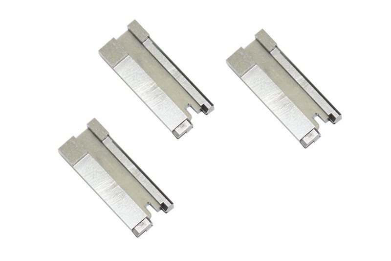
Featured Mold Runner Insert Components







Related Product Catalogue and Quotation










Why Engineers Source Mold Runner Inserts from SUUXIANG
Review critical interfaces, select a practical process route, and keep inspection and revision requirements visible before production begins.
Drawing-Led DFM Review
We review runner geometry, datum references, tool access, shutoff details, and manufacturability questions before quotation or production commitments.
Process Route Planning
CNC machining, wire EDM, sinker EDM, grinding, and fitting are planned around geometry, material condition, surface requirements, and access constraints.
Critical Dimensions First
Priority dimensions, functional interfaces, and tolerance relationships are identified from the drawing to guide machining sequence and inspection planning.
EDM and Grinding Strategy
Electrode needs, wire paths, grinding stock, and heat-treatment sequence are reviewed when runner insert geometry requires controlled finishing work.
Inspection Matched to Requirements
Inspection methods and reporting expectations are aligned with the order, focusing on agreed critical features and documented quality requirements.
Revision Visibility
Drawing revisions, clarified specifications, and delivery information remain visible through project coordination, helping teams avoid preventable manufacturing misunderstandings.
Precision Tooling Component Families
Configure the process route, material, critical dimensions and inspection evidence around your drawing—not an assumed catalog part.

CNC Machining Services
Precision CNC machining services for drawing-based parts that require disciplined DFM review, accessible tool paths, datum control and an inspection plan aligned to critical dimensions before production is committed.
Upload a Drawing
CNC Milling
Custom CNC milling services for prismatic and contoured components, including pockets, profiles, cooling features and mounting geometry. Review machining access, clamping strategy, remaining stock and tolerance priorities before selecting the route.
Upload a Drawing
CNC Turning
Precision CNC turning services for rotational parts such as pins, bushings, sleeves, shafts and locating features. Define datums, concentricity requirements, thread details, material condition and inspection method with the RFQ.
Upload a Drawing
5-Axis Machining
5-axis CNC machining supports complex angled surfaces, compound geometry and features that benefit from fewer setups. Feasibility depends on tool reach, workholding, datum transfer, surface requirements and the specified tolerance stack.
Upload a Drawing
Swiss & Micro Machining
Swiss machining and micro machining address small, slender or detail-intensive components where support, concentricity and handling affect results. Submit complete dimensions, material, quantity and measurement requirements for an appropriate process review.
Upload a Drawing
Wire & Sinker EDM
Wire EDM and sinker EDM services support hardened materials, narrow features, internal corners and geometry beyond conventional cutter access. Electrode design, wire path, finish targets, recast-layer considerations and downstream fitting should be reviewed together.
Upload a Drawing
Precision Grinding
Precision surface and profile grinding is used where flatness, parallelism, profile control or final-size correction is critical. Define grinding stock, heat-treatment sequence, datum surfaces and inspection conditions before machining begins.
Upload a Drawing
Mold Core & Cavity Inserts
Precision mold core and cavity inserts are configured from part geometry, resin behavior, cooling needs and mold layout. Drawing review should identify shutoffs, venting, polishing areas, steel selection, EDM strategy and dimensional interfaces.
Upload a Drawing
Ejector & Ejection Components
Ejector pins, sleeves and ejection components are specified around stroke, guidance, clearance, wear conditions and mating geometry. Provide diameter tolerances, hardness or treatment requirements, surface expectations and assembly context for review.
Upload a Drawing
Core Pins, Guide & Locating Components
Core pins, guide pins and locating components establish functional alignment and repeatable positioning in a mold assembly. Critical considerations include fit class, engagement length, wear surfaces, datum relationships, material condition and replacement strategy.
Upload a Drawing
Slides, Lifters, Gates & Mold Accessories
Mold slides, lifters, gates and accessories support part release, side actions and controlled material flow. Assess travel, interference, shutoff geometry, gate location, wear allowance and assembly interfaces before releasing the component drawings.
Upload a Drawing
Connector Mold Components
Precision connector mold components require close control of fine features, pin relationships, insert alignment and repeated molding conditions. Share mating-part context, cavity layout, material requirements, critical dimensions and inspection priorities with the RFQ.
Upload a Drawing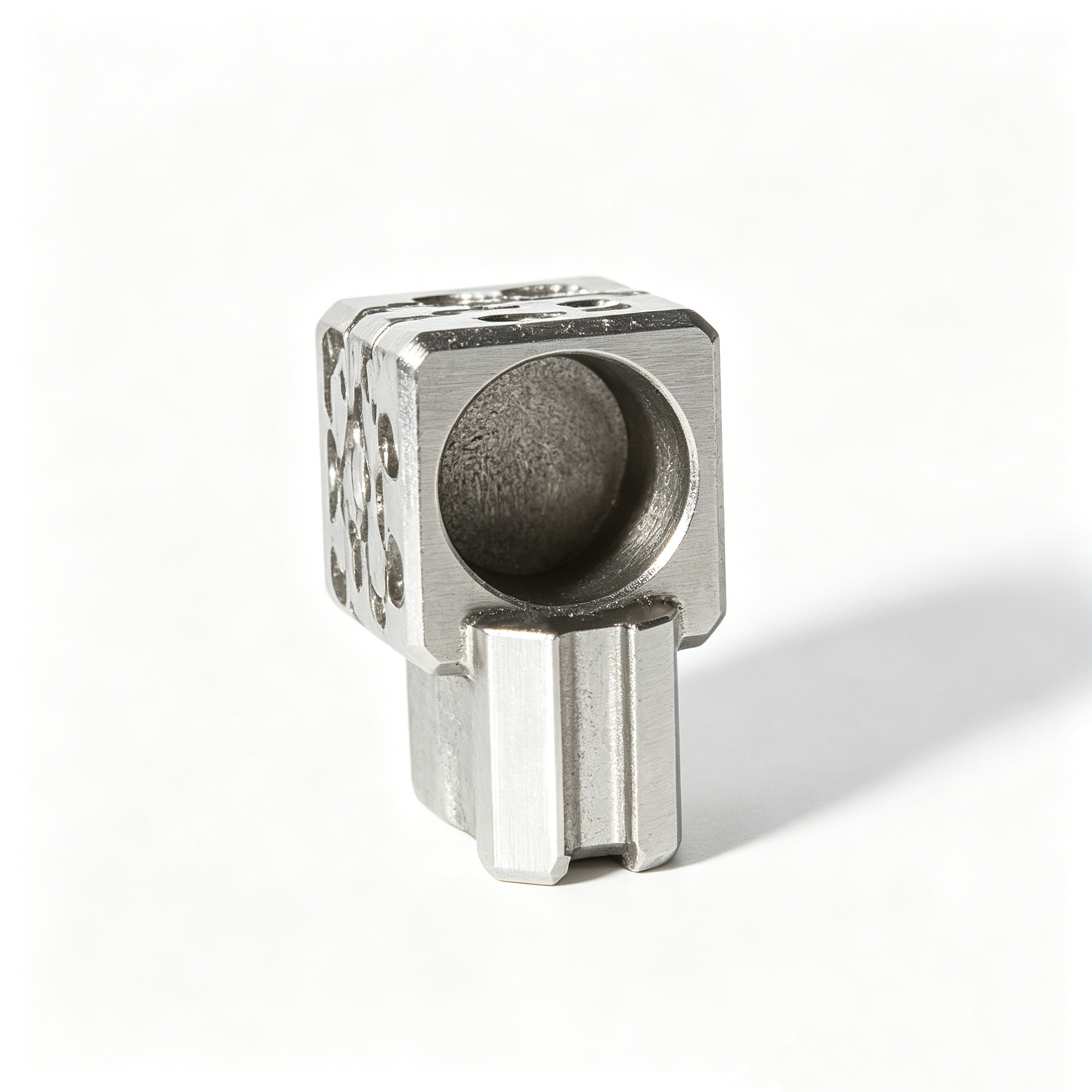
Stamping Die Components
Precision stamping die components are produced to the functional relationships of the die set, including punch, die, guide and locating features. Material, heat treatment, clearance, profile accuracy and fitting requirements govern the process plan.
Upload a Drawing
Injection, MIM, CIM & Overmolding Tooling
Injection, MIM, CIM and overmolding tooling components are reviewed within verified production scope. Provide the molded material, shrinkage assumptions, insert interfaces, parting requirements, critical features and expected operating conditions.
Upload a Drawing
Machining Materials
CNC machining materials are selected against strength, wear, corrosion, stability, machinability and downstream treatment needs. State the exact grade or approved alternatives, material condition, certification needs and application environment before quotation.
Upload a Drawing
Surface Finishes & Heat Treatment
Surface finishing and heat treatment must be matched to functional surfaces, dimensional change risk, wear demands and assembly fits. Identify finish zones, roughness targets, masking needs, hardness requirements and post-treatment inspection expectations.
Upload a Drawing
Quality, Metrology & Documentation
Precision inspection, metrology and quality documentation are planned from drawing-defined critical dimensions and agreed acceptance criteria. Specify report format, sampling expectations, datum scheme, gauge needs, material records and revision-controlled documentation requirements.
Upload a Drawing
Prototyping & Low-Volume Production
Rapid prototyping and low-volume manufacturing support drawing-driven validation, bridge quantities and controlled revisions. Early review should confirm material availability, process route, critical dimensions, inspection scope, quantity breaks and target delivery requirements.
Upload a DrawingMaterial Options for Mold Runner Inserts

Pre-Hardened Tool Steel
Suitable for runner inserts requiring a stable machining route and moderate production wear resistance. Buyers should specify steel grade, required hardness condition, resin type, critical dimensions and any surface-finish or inspection requirements.

Through-Hardening Tool Steel
Used where higher wear resistance is needed after machining and heat treatment. The drawing should define material grade, target hardness, heat-treatment sequence, grinding stock, datum surfaces and dimensional checks required after hardening.

Corrosion-Resistant Stainless Steel
Considered for molding environments where corrosion resistance, polishability or moisture exposure affects insert life. Confirm the stainless grade, hardness condition, resin additives, finish requirement and whether EDM, grinding or post-treatment is needed.

High-Wear Cold Work Steel
A potential choice for runner areas exposed to abrasive or filled resins, subject to project review. Provide resin composition, expected wear location, heat-treatment specification, surface requirement and replaceability expectations for the insert.

Beryllium Copper Alloys
May be evaluated for localized thermal-conductivity needs where the application and safety requirements support its use. Buyers should identify the alloy specification, heat-treatment condition, cooling context, mating steels and required inspection documentation.
Mold Runner Inserts: Machining, EDM and Grinding

CNC Milling
CNC milling establishes insert profiles, runner forms, pockets and accessible reference features. It is typically selected where cutter access supports the geometry, with machining allowance retained when subsequent EDM or grinding is required.

Wire EDM
Wire EDM produces narrow slots, sharp internal profiles and through-features that milling tools cannot reach cleanly. The wire path, start-hole location and datum relationship should be reviewed before production to protect critical geometry.

Sinker EDM
Sinker EDM addresses blind cavities, fine gate details and internal runner features where electrode access is practical. Electrode strategy, spark allowance and surface requirements must be aligned with the drawing and downstream fitting needs.


Controlled Fitting
Fitting verifies the functional relationship between the runner insert and its mating mold components. Contact areas, seating faces and shutoff interfaces are evaluated against the approved geometry, avoiding unsupported assumptions about assembly conditions.

Dimensional Inspection
Inspection is planned around critical dimensions, datums, surface requirements and order-specific reporting needs. Measured results and revision status are kept aligned with the agreed drawing so acceptance evidence matches the manufactured runner insert.
Mold Runner Inserts: Compatible Features

Locating Elements
Dowel, key and flat locating features can establish repeatable orientation between runner inserts and surrounding mold components. Final geometry should reflect datum strategy, press-fit requirements, assembly access and the approved drawing.

Guide Features
Guide pins, bushings or dedicated guiding surfaces can support accurate closing and protect working interfaces from misalignment. SUUXIANG reviews engagement length, clearance, wear considerations and machining access before selecting the feature approach.

Gate Interfaces
Gate-adjacent details can be integrated where the insert supports a defined runner and cavity layout. Gate size, land condition, material behavior, serviceability and EDM strategy should be confirmed through the drawing review.

Ejection Interfaces
Clearances, pin passages and support interfaces can be machined for the intended ejection arrangement. Their design depends on runner geometry, release direction, assembly stack-up and whether the component requires fitting after machining.

Identification Marking
Cavity numbers, revision identifiers and orientation marks can aid assembly, maintenance and inspection traceability. Provide marking content, location, depth and surface restrictions so the feature does not interfere with functional mold surfaces.
About SUUXIANG Mold Runner Inserts
SUUXIANG is the public-facing brand of Dongguan SuuXiang Precision Mold Co., Ltd., established in 2010 in Chang’an Town, Dongguan, Guangdong, China. We support international engineering, sourcing and quality teams with drawing-based manufacturing for mold runner inserts, precision mold components, connector tooling and custom CNC parts.
Our workflow combines DFM discussion with CNC milling and turning, multi-axis machining, EDM, precision grinding, fitting and inspection. Before quotation and production commitments, we review critical dimensions, datums, material and heat-treatment requirements, machining access, EDM needs, grinding allowance and inspection expectations.
What distinguishes SUUXIANG is disciplined coordination from revision-controlled drawing review through final documentation. Rather than treating a part as a generic machining request, we help teams define the process route, inspection method and delivery requirements needed for the specific component, application and order.

Mold Runner Inserts: Core Manufacturing Capabilities
DFM and Datum Review
Before machining mold runner inserts, SUUXIANG reviews the drawing, model, mating interfaces, critical dimensions and datum scheme. This establishes an inspectable reference for runner geometry, sealing features and location before a process route or production commitment is discussed.
- Identify critical flow-control, fit and shutoff dimensions
- Check datum accessibility across milling, EDM and grinding
- Review tool access, corner conditions and feature transitions
- Record drawing revisions and open technical questions

EDM Strategy for Defined Features
Deep slots, sharp internal forms and restricted-access details may require wire EDM or sinker EDM after the machining sequence is assessed. Electrode design, wire path, stock condition and downstream finishing are planned against the specified geometry rather than assumed from a generic part model.
- Match EDM method to feature geometry and access
- Review electrode requirements for blind or detailed forms
- Plan finish stock for subsequent grinding or fitting
- Clarify surface and dimensional inspection priorities

Grinding Allowance and Fitting
Precision runner inserts often depend on controlled grinding stock and fitting relationships, not nominal machining alone. SUUXIANG reviews where material must remain for finish grinding, how surfaces relate to their datums and which interfaces require verification during assembly-oriented inspection.
- Define grinding allowance before heat-treatment sequencing
- Protect reference faces used for final location checks
- Assess fit-sensitive surfaces and shutoff relationships
- Avoid removing finish stock during earlier operations

Inspection Planned From Drawings
Inspection planning begins with the customer’s drawing and agreed critical-to-quality requirements. SUUXIANG aligns measurement methods, reporting needs and revision identification with the order, so inspection evidence addresses the dimensions and surfaces that matter to the runner insert application.
- Prioritize critical dimensions, datums and surface requirements
- Align inspection methods with accessible feature geometry
- Confirm report format and traceability expectations
- Keep revision status visible through production coordination

Mold Runner Inserts: Beyond a Generic Machining Quotation
Compare the drawing review, process planning and inspection alignment required before runner-insert production begins.
← Swipe left or right to view →
Mold Runner Inserts: Drawing-to-Delivery Process
A drawing-led workflow that aligns DFM, process planning, precision machining, inspection, and delivery coordination with the approved order requirements.
RFQ Technical Intake
Submit 2D drawings, 3D models when available, material specifications, quantities, application context, delivery target, and inspection needs so the quotation discussion begins with usable technical inputs.
DFM and Drawing Review
Review critical dimensions, datums, runner geometry, machining access, shutoff conditions, heat-treatment sequence, EDM needs, grinding stock, and inspection methods before production commitments are confirmed.
Process Route Planning
Plan CNC milling, turning, multi-axis operations, electrode strategy, wire paths, and workholding around the approved revision, material condition, and features that control runner flow.
Machining and EDM
Machine features using the selected CNC route, then apply EDM or precision grinding where geometry, surface requirement, hard material condition, or finishing allowance warrants it.
Fitting and Verification
Fit and verify interfaces, shutoffs, and locating features against the drawing; keep revision status and agreed inspection requirements visible throughout the controlled production workflow.
Inspection and Delivery
Inspect critical characteristics with the specified methods, compile documentation that matches the agreed plan, then coordinate protective packing and delivery information for the finished order.
How to Source Mold Runner Inserts
Provide the drawing, requirements and quality priorities needed for a disciplined review before quotation, sampling or production.
Upload Your Drawing Package
Send the 2D drawing and, where available, the 3D model, identifying revision status, application context, mating features, and runner-flow or shutoff requirements.
Define Material and Quantity
Specify material, heat-treatment requirements, quantity, target delivery date, and whether the requirement is for evaluation samples, replacement inserts, or production tooling.
Mark Critical Requirements
Identify critical dimensions, datums, surface requirements, fit conditions, and any runner geometry that affects machining access, EDM strategy, grinding stock, or inspection planning.
Review DFM and Inspection
Review SUUXIANG feedback on manufacturability, process route, inspection method, revision control, and reporting needs before confirming a quotation or production commitment.
Confirm the Production Plan
Align the approved drawing revision, delivery milestones, documentation scope, and communication points so machining, EDM, grinding, fitting, and final inspection follow the verified requirements.
Mold Runner Inserts: Verified Certifications and Quality Documentation
Mold Runner Inserts: Engineering Project Feedback
The drawing review identified an EDM-access issue before release. After the revised datum callout, the runner insert set arrived with all 12 measured critical dimensions included in the inspection report, which shortened our incoming-quality review.
SUUXIANG coordinated two drawing revisions without losing traceability between the cavity-side and runner inserts. The final delivery matched our staged build schedule, and the first fitting check required no rework to the specified locating interfaces.
For a six-cavity family tool, the team clarified the shutoff and grinding-stock requirements before machining. We received the component set with material identification and dimensional records, allowing our toolroom to complete assembly one day earlier than planned.
Mold Runner Inserts FAQ for RFQ Preparation
Prepare a clearer drawing-based inquiry by defining the requirements that affect process planning, inspection, delivery, and documentation.
What information should I include in a mold runner inserts RFQ?
Is there a minimum order quantity for mold runner inserts?
How long does a custom mold runner insert take to manufacture?
Can I order a prototype or sample before production?
Which materials can be used for mold runner inserts?
What inspection reports are available for mold runner inserts?
How are drawings and intellectual property protected during an RFQ?
What payment and shipping details should I provide?
The Complete Buyer’s Guide to mold runner inserts
Use this practical decision framework to specify mold runner inserts, compare materials and configurations, assess drawing-based suppliers, control tooling risk, and avoid costly design, sourcing, and maintenance mistakes.
1. What Are mold runner inserts?
A two-plate injection mold commonly carries the sprue, runner, and gate at its parting-line interface. Mold runner inserts are replaceable tooling pieces that form those flow features locally: they may define a runner branch or gate, block a path, redirect resin, or provide a serviceable wear surface before melt enters the cavity. https://www.beaumontinc.com/injection-molding-glossary/runner
At the parting line, an insert can be removed for controlled rework while the surrounding mold plate, cavity, and alignment features remain intact. This lets the toolmaker alter a localized gate or runner condition, recover a worn surface, or correct flash without remachining a large plate.
One replaceable interface is particularly useful where filled resin, repeated production contact, or trial-driven flow changes concentrate risk. The drawing should define its datum relationship, shutoff faces, runner and gate geometry, material state, and inspection points so resin flow and future maintenance remain controlled. https://www.ptonline.com/blog/post/tooling-how-to-properly-size-gates-runners-and-sprues-part-5-of-5
2. Evolution of mold runner inserts
Two-plate cold-runner molds traditionally machined runner and gate geometry directly into the mold plates. That approach is durable for stable, simple layouts, but a gate correction, erosion repair, or balance change can require reworking the plate rather than a localized component.
Three serviceable insert functions—runner, gate, and shutoff or turn-off—separate flow-control geometry from the surrounding steel. In family molds, turn-off inserts can block or redirect flow to selected cavities; replaceable gate inserts also allow gate-size adjustment without re-EDM of the original gate diameter (https://www.moldmakingtechnology.com/products/runner-components-gate-insert-and-runner-turn-off-to-control-mold-runner-systems).
Glass-filled and mineral-filled resins concentrate wear at gates, runners, and sealing edges, making replaceable wear areas practical. Procurement teams should therefore specify insert location datums, retention, parting-line relationship, service access, material and heat-treatment requirements, spare quantity, and inspection criteria so maintenance windows and trial-driven modifications stay localized.
3. Types of mold runner inserts
Mold runner inserts are classified by the flow, wear, or thermal problem they isolate. The drawing should identify whether each insert belongs to a cold-runner path or interfaces with a hot-runner system.
| Type | Purpose | Typical Situation | Key Constraint |
|---|---|---|---|
| Runner channel | Shape cold-runner flow | Two- or three-plate mold | Balanced section and datum fit |
| Gate insert | Control gate land | Gate tuning or wear service | Gate geometry and flash |
| Turn-off | Block or redirect flow | Family mold | Sealing face orientation |
| Wear insert | Protect high-wear zone | Abrasive resin | Replaceable location |
| Cooling-enhanced | Remove local heat | Runner hot spot | Wall strength |
| Hot-runner-adjacent | Interface with hot system | Manifold or nozzle zone | Thermal clearances |
Cold-Runner Flow Inserts
Runner channel inserts form or modify the cold-runner passage in two- or three-plate tooling. Their removable construction permits runner-diameter changes or parting-line service; the constraint is a balanced flow path and positive datum location.
Gates And Turn-Offs
Gate inserts localize the gate land so gate size can be adjusted or renewed without reworking a large cavity plate. Runner shutoff or turn-off inserts block or redirect flow in family molds; sealing faces, orientation, and flash control are critical.
Wear, Cooling, And Hot Runner
Wear inserts protect runner intersections or abrasive-resin contact areas and simplify replacement. Cooling-enhanced inserts address local hot spots, while hot-runner-adjacent inserts require manifold, nozzle, heater, and thermal-clearance data rather than being quoted as cold-runner components.
4. Materials for mold runner inserts
Material selection sets the wear, corrosion and thermal limits of mold runner inserts. Match the insert to the resin, cycle target, cooling circuit, mating steel and planned maintenance interval before releasing the drawing.
| Material Family | Hardness/Wear | Corrosion/Polish | Thermal/Machining | Best Fit |
|---|---|---|---|---|
| Pre-hardened stainless | Moderate | High / good | Moderate / good | Corrosive resins |
| Through-hardening tool steel | High after treatment | Moderate / good | Moderate / moderate | General production |
| High-hardness wear grade | Very high | Grade dependent | Lower / difficult | Glass-filled resin |
| Copper alloy | Low wear resistance | Moderate / fair | High / easy | Local hot spots |
| Specialty conductive material | Grade dependent | Grade dependent | High / variable | Targeted cooling |
Wear And Corrosion Match
Glass-filled and mineral-filled resins accelerate runner and gate wear; high-hardness tool steels are usually the safer wear route. Corrosive resin systems shift priority toward stainless grades and documented maintenance.
420 stainless and similar pre-hardened grades balance corrosion resistance, polishability and practical machining. Confirm the actual heat-treatment condition and hardness on the order.
Thermal And Service Strategy
Copper alloys and specialty high-conductivity materials remove localized heat faster than tool steel, but require careful support and mating-surface design. Use them where cooling analysis identifies a hot spot, not as a default runner material.
Each drawing review should define resin, expected cycles, cooling access, contact loads and replacement method. Inspection should verify the critical runner profile after fitting or grinding.
5. Custom mold runner insert options
Custom mold runner inserts should be defined from the runner layout, not selected as decorative variants. SUUXIANG reviews flow features, installation interfaces, service access, and inspection identifiers against the released drawing package.
| Option | Performance Purpose | Required Input |
|---|---|---|
| Runner profile | Flow and balance | Section geometry and resin |
| Gate geometry | Fill and freeze control | Gate size and molding window |
| Retention method | Location and service access | Mating-part interface |
| Marking | Revision traceability | Text, location, and drawing revision |
Flow And Gate Geometry
Runner profile, branch dimensions, gate land, and gate diameter affect pressure loss, shear, freeze-off, and cavity balance. Provide the 2D drawing, 3D model, resin grade and filler content, cavity count, and intended gate location.
Installation And Serviceability
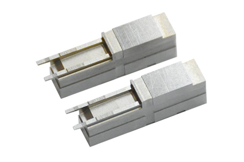
Press-fit, screw-retained, or positively located inserts require mating-pocket dimensions, datum references, retention details, and assembly direction. Shutoff angles, vent positions, cooling passages, and interchangeable insert boundaries should be reviewed with molding temperature, injection conditions, and maintenance access.
Finish And Identification

Surface finish, coating, laser marking, and revision marks should serve release, wear control, assembly verification, or traceability. Specify the required finish callout, marking content and location, coating requirement, inspection method, and the revision-controlled drawing to be manufactured.
6. Construction quality that protects production
Construction quality is established on the drawing’s functional datums, not on isolated feature tolerances. Each interface must preserve sealing, flow geometry, and serviceable replacement after machining and heat treatment.
Datums, Fits, And Alignment
Three datum references should locate the insert, runner centerline, and parting surface. Their tolerance stack determines repeatable seating; uncontrolled clearance can shift alignment, create leakage paths, or make a replacement insert unsafe.
Sealing And Flow Surfaces
One continuous parting-line contact must remain protected around the runner. Flatness, fit, runner finish, controlled radii, and clean gate transitions reduce flash, pressure loss, stagnant corners, and cavity-to-cavity flow imbalance.
Edges, Heat Treatment, And Records
Zero loose burrs are acceptable at runner, gate, and shutoff edges because fragments can damage sealing faces or contaminate production. Heat-treatment distortion should be anticipated with grinding stock, then verified by dimensional inspection, surface checks, and revision-linked records.
7. Choosing a mold runner insert manufacturer
A capable manufacturer reviews mold runner inserts as functional interfaces, not isolated dimensions. Before award, compare the evidence attached to the drawing review, process plan, inspection plan, and delivery commitment.
| Evaluation Area | Evidence To Request | Interface Test |
|---|---|---|
| Engineering | Marked drawing and DFM feedback | Are datums and sealing faces understood? |
| Materials | Certificates and heat-treatment plan | Is hardness linked to wear conditions? |
| Manufacturing | CNC, EDM, grinding process route | Can inaccessible features be explained? |
| Quality | First-article report and instrument plan | Are critical dimensions traceable? |
| Control | Revision log and shipment plan | Can changes be contained before production? |
Engineering Review Evidence
1 drawing review should identify runner centerlines, parting-line sealing, gate relationship, datums, machining access, and EDM or grinding requirements.
2 DFM questions reveal depth: Which surfaces locate the insert? What clearance, flash risk, wear mechanism, resin, and mating-component conditions govern acceptance?
Production And Quality Controls
1 controlled route should connect material traceability, heat-treatment coordination, CNC, wire or sinker EDM, grinding, fitting, and final inspection.
2 first-article reporting should identify measured critical dimensions, instruments, datum setup, drawing revision, and deviations before shipment.
Delivery And Support
1 realistic lead-time communication separates engineering release, material availability, outside processing, machining, inspection, and packing.
2 shipment support should preserve identification, revision status, corrosion protection, protective packaging, and a defined route for post-delivery questions or corrective action.
8. Common mold runner insert sourcing mistakes
Before purchase-order release, a 15-minute drawing-and-risk review prevents most avoidable insert disputes. For mold runner inserts, the costliest errors usually appear at fitting, first trial, or replacement.
Complete Drawing Definition
One incomplete drawing can leave gate geometry, mating interfaces, or revision status open to interpretation. The consequence is rework or a mismatched insert.
Before release, provide controlled 2D and 3D files, functional datums, tolerance zones, and a revision identifier.
Steel Must Match Resin
One lowest-price steel choice can fail when filled resin abrades runner or gate surfaces. The consequence is rapid wear or unstable flow.
Before release, state resin grade, filler percentage, required hardness, heat-treatment condition, and expected production exposure.
Thermal Fit And Stack-Up
One copied insert may share nominal dimensions yet differ in thermal expansion, stack-up, or seating datum. The consequence is leakage, flash, or binding.
Before release, provide pocket measurements, operating temperature, assembly drawing, and clear fit responsibility.
Finish Inspection And Spares
One omitted finish callout leaves polishing, EDM texture, and gate condition subjective. The consequence is flow variation or rejected fit.
Before release, define Ra or an approved sample, inspection report, marking, and spare-part interchangeability needs.
9. From drawing release to first trial
One controlled release package prevents CAD, PDF, and purchase-order requirements from drifting apart. Before SUUXIANG starts routing work, engineering, procurement, quality, and the mold shop should agree on the trial objective.
Release The Technical Package
Two files should anchor release: the controlled 2D drawing and matching 3D model. Engineering identifies datums, critical dimensions, resin contact, gate or shutoff function, material, heat treatment, and surface requirements.
Close Commercial And Quality Gates
One quotation review should document the agreed process route, quantity, delivery target, and sample requirement. Procurement locks the revision on the order while quality defines inspection points, report format, traceability needs, and acceptance criteria.
Verify Installation And Trial
At receipt, quality verifies identity, revision, packaging condition, and agreed inspection evidence before release to the mold shop. During the first trial, the mold shop records fit, runner flow, flash, wear contact, and corrective actions; engineering approves any controlled revision.
10. mold runner inserts pricing and lead time
1-off prototype orders usually carry the highest unit cost because programming, workholding, electrodes, and first-article inspection are spread across few parts. SUUXIANG should quote only after reviewing the drawing, material, datum scheme, and required report.
2-week targets are not a promise: material grade, dimensions, tight tolerances, milling or EDM complexity, heat treatment, coatings, inspection scope, documentation, and expedited routing all change the process plan. Send identical RFQ inputs to each supplier: 2D and 3D files, revision, quantity, critical dimensions, material, finish, reports, and required date.
| Quantity stage | Unit-cost tendency | Lead-time planning |
|---|---|---|
| Prototype: 1–2 pieces | Highest; setup spread over few parts | Allow drawing review, programming, and first article |
| Small batch: 3–50 pieces | Drops as setups repeat | Plan material and outside processes |
| Repeat order: released design | Lowest when route is unchanged | Often shorter after revision confirmation |
Upload Your Mold Runner Inserts Drawing for Review
Send your drawing, material, quantity, critical dimensions, inspection needs, and delivery target for a disciplined manufacturing review and quotation.