
In-Process Inspection for Precision Parts
Move from drawing review to inspected CNC parts, mold components, and connector tooling with in-process inspection focused on critical dimensions and revision control.
Representative Parts and Tooling for In-Process Inspection





Drawing-Based Parts and Tooling for Quotation


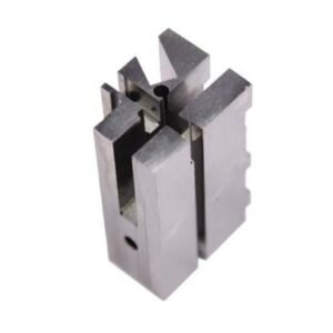





In-Process Inspection Advantages for Drawing-Based Parts
A disciplined workflow aligns drawing review, process decisions and inspection evidence with the features that matter to your order.
DFM Before Commitment
Review machining access, datum strategy, EDM needs and grinding allowance before quotation assumptions become production constraints.
Critical Dimensions Prioritized
Identify critical-to-quality features and define suitable checkpoints around operations that can influence fit, geometry or function.
Planned Process Routes
Coordinate CNC machining, EDM, grinding and fitting in an order that protects precision features and leaves appropriate finishing stock.
Revision Visibility Maintained
Keep drawing revisions, clarified requirements and project communication visible so manufacturing follows the current agreed technical baseline.
Order-Matched Inspection Evidence
Align inspection methods and final documentation with the drawing, quality expectations and verified inspection plan for the specific order.
Precision Parts and Tooling We Support
Drawing-driven manufacturing categories for custom parts, mold components, connector tooling, and die work—configured to verified material, quality, and delivery requirements.

CNC Machining Services
Precision CNC machining services for drawing-based parts requiring coordinated milling, turning, EDM, grinding, fitting, and inspection. Review focuses on critical dimensions, datum strategy, material condition, tolerance stack, accessible features, and the inspection evidence needed before production is committed.
Upload a Drawing
CNC Milling
Custom CNC milling services for prismatic, contoured, and feature-rich components. Tool access, clamping approach, corner radii, wall geometry, machining allowance, and datum transfer should be reviewed against the drawing before selecting a practical milling route.
Upload a Drawing
CNC Turning
Precision CNC turning services for shafts, sleeves, bushings, threaded features, and rotational components. Diameter relationships, concentricity, runout, surface requirements, material condition, and secondary operations are evaluated from the drawing and mating-part context.
Upload a Drawing
5-Axis Machining
5-axis CNC machining for components with compound angles, multi-face features, and geometry that benefits from fewer setups. A drawing review confirms tool reach, fixturing, datum control, surface requirements, and whether simultaneous machining is appropriate for the part.
Upload a Drawing
Swiss & Micro Machining
Swiss machining and micro machining for small, detailed components where feature relationships and handling require disciplined process planning. Review includes material form, slender geometry, small diameters, burr control, inspection access, and dimensional priorities defined by the application.
Upload a Drawing
Wire EDM Services & Sinker EDM Services
Wire EDM and sinker EDM services for precise profiles, deep or inaccessible features, hardened materials, and mold details not efficiently produced by conventional cutting alone. Electrode strategy, wire path, corner requirements, recast considerations, and finishing allowances require early review.
Upload a Drawing
Precision Grinding
Precision surface and profile grinding for flatness, parallelism, profile control, and tight dimensional relationships after machining or heat treatment. Grinding stock, datum sequence, material condition, surface finish, and inspection method should be established before release.
Upload a Drawing
Mold Core Inserts & Mold Cavity Inserts
Precision mold core and cavity inserts manufactured from customer drawings and models. Process planning considers shutoff geometry, cooling or feature access, heat-treatment sequence, EDM requirements, grinding stock, fitting interfaces, and the dimensions that govern molded-part performance.
Upload a Drawing
Ejector & Ejection Components
Ejector pins, sleeves, and ejection components produced as configurable drawing-based parts rather than catalog stock. Requirements commonly include fit relationships, hardness or treatment needs, tip geometry, surface condition, lubrication context, and dimensional checks relevant to reliable ejection.
Upload a Drawing
Core Pins, Guide & Locating Components
Core pins, guide pins, and locating components for mold assemblies where alignment, wear surfaces, and mating relationships matter. Drawings should identify functional datums, fit classes, hardness requirements, surface finish, and the inspection points needed to verify interchangeability.
Upload a Drawing
Slides, Lifters, Gates & Mold Accessories
Mold slides, lifters, gates, and accessories manufactured to assembly-specific drawings. Review addresses travel and clearance interfaces, shutoff surfaces, tool access, wear areas, heat-treatment sequence, fitting needs, and any mating components that influence final function.
Upload a Drawing
Connector Mold Components
Precision connector mold components for fine-pitch, multi-cavity, and interface-sensitive tooling applications. Manufacturing planning considers small features, datum relationships, EDM and grinding strategy, wear surfaces, material requirements, and inspection methods aligned with connector-part geometry.
Upload a Drawing
Stamping Die Components
Precision stamping die components for forming, punching, guiding, and locating functions. A responsible review considers material and hardness, cutting or forming edges, clearance relationships, grinding allowance, wire-EDM paths, mating-part interfaces, and revision-controlled documentation.
Upload a Drawing
Injection Mold Components, MIM, CIM & Overmolding Tooling
Tooling and component work associated with injection molding, metal injection molding, ceramic injection molding, and overmolding when within verified production scope. Drawings should clarify material behavior, molding interfaces, cavity details, inserts, surface requirements, and quality expectations.
Upload a Drawing
Machining Materials
CNC machining materials selected against the drawing, application, dimensional requirements, and any specified condition or certification needs. Material availability, machinability, heat-treatment sequence, corrosion environment, and traceability expectations should be confirmed before quotation and release.
Upload a Drawing
Surface Finishes & Heat Treatment
Surface finishing and heat treatment planned around functional surfaces, dimensional change, corrosion needs, wear requirements, and subsequent grinding or EDM. Specify finish type, target condition, masking needs, critical dimensions, and any reporting or certification requirements with the RFQ.
Upload a Drawing
Quality, Metrology & Documentation
Precision inspection, metrology, and quality documentation aligned to the order and an agreed inspection plan. Define critical dimensions, datum references, measurement method, sampling expectations, report format, material evidence, revision level, and traceability requirements before production begins.
Upload a Drawing
Prototyping & Low-Volume Production
Rapid prototyping and low-volume manufacturing for drawing-driven parts that need a controlled path from design review to inspected delivery. Provide models, drawings, quantity, material, critical features, quality requirements, target date, and application context to assess a suitable process route.
Upload a DrawingMaterial Considerations for In-Process Inspection

Tool Steels
Used for mold cores, cavity inserts, slides and stamping-die elements where wear resistance and post-heat-treatment stability matter. Grade, hardness condition, EDM strategy and grinding stock should be defined during drawing review.

Stainless Steels
Applied to corrosion-sensitive mold components, connector tooling and custom machined parts. Alloy selection, condition, surface requirement and critical dimensions are reviewed to plan machining access and appropriate in-process inspection checkpoints.

Alloy Steels
Common for structural tooling, guide elements and die components requiring strength and controlled heat-treatment response. The drawing should identify material grade, hardness requirement, datum scheme and dimensions requiring staged verification.

Aluminum Alloys
Often selected for fixtures, prototype tooling and lightweight precision parts where machinability and handling matter. Alloy designation, temper, surface treatment and thin-wall features affect process planning and dimensional inspection needs.

Copper Alloys
Used for electrodes, thermal-management inserts and specialized tooling features that benefit from electrical or thermal conductivity. Material grade, electrode geometry, wear expectations and dimensional priorities guide the machining and inspection plan.
In-Process Inspection Across Critical Process Routes


Wire EDM
Wire EDM is considered for precise profiles, narrow slots and hardened-workpiece features where a controlled wire path is appropriate. Inspection focuses on profile accuracy, datum relationship, corner conditions and stock remaining for subsequent fitting or grinding.

Sinker EDM
Sinker EDM forms cavities, deep details and features with limited cutting-tool access using a planned electrode strategy. Process checks help confirm electrode wear, cavity geometry, surface requirements and the remaining allowance for finishing operations.

Precision Grinding
Precision grinding refines size, flatness, parallelism and surface condition after the planned machining or heat-treatment sequence. In-process inspection verifies grinding stock, datum control and critical measurements before parts move to fitting or final review.

Component Fitting
Fitting evaluates how mating mold, connector-tooling or die components assemble against the drawing intent. Controlled checks address contact areas, movement, clearances and functional relationships, with deviations communicated through documented revision control.
In-Process Inspection of Component Features

Locating Features
Datums, locating holes, flats and guide interfaces establish repeatable part orientation. Identify the functional references and critical relationships on the drawing so in-process inspection can verify positioning before downstream EDM, grinding or fitting.

Ejection Parts
Ejector pins, sleeves, blades and return elements require clear dimensions, material and fit requirements. Drawing-defined inspection checkpoints help confirm seating, movement-related interfaces and critical diameter relationships before mold assembly.

Gate Details
Gate inserts, gate bushings and related flow-path features should specify geometry, surface expectations and mating references. Review these details early to select practical machining, EDM and inspection methods for the required tool function.

Slide Components
Slides, lifters, wear interfaces and locking elements depend on controlled fit, travel and datum relationships. Provide mating-part context where available so machining allowances, grinding stock and inspection priorities can be planned responsibly.

Packaging Requirements
Part identification, protective packaging, labeling and document requirements can be defined with the RFQ. These instructions support traceable delivery and help protect finished precision surfaces, edges and functional features during handling and shipment.
About SUUXIANG Precision Manufacturing
SUUXIANG is the sole public-facing brand of Dongguan SuuXiang Precision Mold Co., Ltd., established in 2010 in Chang’an Town, Dongguan, Guangdong, China. XiaoCheng Huang is the founder and legal representative. We help international engineering, sourcing, and quality teams translate drawings and specifications into custom CNC parts, precision mold components, connector tooling, and stamping-die components.
Our engineering-led workflow combines drawing review, DFM, CNC milling and turning, EDM, precision grinding, fitting, and inspection planning. Before quotation or production commitments, we discuss critical dimensions, datums, material and heat-treatment requirements, machining access, surface priorities, and documentation expectations relevant to the order.
What differentiates SUUXIANG is disciplined coordination around the drawing, not a generic parts catalog. In-process inspection is planned around meaningful manufacturing transitions and critical features, with revision information and inspection evidence aligned to the agreed project requirements. Upload your drawing with material, quantity, and quality needs to begin a practical review.

In-Process Inspection Planning for Critical Features
Datum Strategy Before Setup
In-process inspection starts by aligning the drawing’s functional datums with practical workholding and measurement references. Buyers should identify mating relationships, critical dimensions, and datum precedence so setup choices and inspection results remain meaningful across machining, EDM, grinding, and fitting steps.
- Identify drawing datums and functional mating references
- Flag critical-to-quality dimensions before quotation
- Review whether clamping obscures required measurement features
- Keep datum interpretation visible through revision control

Machining Access Reviewed Early
A feature can be toleranced correctly yet remain difficult to machine or inspect without suitable tool access. SUUXIANG reviews cavity depth, corner conditions, reach, clamping direction, and probe access against the supplied drawing and model before committing to a process route.
- Assess cutter reach and internal-corner limitations
- Check access for probes, gauges, and visual review
- Discuss fixture direction and accessible reference surfaces
- Escalate geometry risks before production planning

EDM and Grinding Allowances
EDM and grinding require planned stock, sequence, and reference surfaces to protect critical geometry. In-process inspection checkpoints can confirm that pre-machined conditions support the intended wire path, electrode strategy, heat-treatment sequence, and final grinding operation without consuming required allowance.
- Define machining stock before EDM or grinding
- Review electrode, wire-path, and burn-area requirements
- Coordinate heat treatment with finishing allowances
- Verify interim dimensions against the process sequence

Inspection Methods Match Requirements
Inspection planning should match each requirement to an appropriate method, timing, and record expectation. Buyers can specify dimensional priorities, geometric tolerances, surface concerns, sampling needs, and report formats; SUUXIANG then reviews those inputs against the drawing-driven manufacturing and inspection workflow.
- Link critical features to practical measurement methods
- Set checkpoints before downstream operations
- Clarify report, traceability, and revision requirements
- Include quantity and delivery priorities in the RFQ

In-Process Inspection for Drawing-Based Work
Compare a review-led manufacturing workflow with a typical quote-only supplier before releasing precision parts to production.
← Swipe left or right to view →
In-Process Inspection: Production to Delivery
A controlled workflow aligns drawing review, process routing, critical-dimension checks, final documentation, and delivery coordination for custom precision parts and tooling components.
Review Drawings and DFM
SUUXIANG reviews drawings, models, materials, quantities, critical dimensions, datums, surface requirements, heat-treatment sequence, and inspection expectations before quotation or production commitments.
Plan Process and Controls
The team defines the machining route, tool access, machining allowances, electrode or wire path needs, grinding stock, checkpoints, and revision-control requirements for the order.
Machine Critical Part Features
CNC milling, turning, multi-axis work, Swiss or micro machining are applied as appropriate, with in-process inspection focused on features that affect downstream operations.
Apply EDM and Grinding
Wire EDM, sinker EDM, and precision grinding are scheduled where the drawing requires them, verifying critical dimensions and allowances before features become difficult to correct.
Fit and Verify Components
Where applicable, components proceed through fitting and dimensional verification against the agreed inspection plan, with deviations and revisions kept visible through project coordination.
Document Pack and Coordinate
Final inspection records are matched to the order and verified plan before packing, while delivery coordination keeps the customer informed of shipment-ready project status.
Start Your In-Process Inspection Project
Move from drawing review to controlled production with requirements, checkpoints, and delivery information aligned before work begins.
Submit Drawings and Requirements
Send the 2D drawing, available 3D model, material, quantity, critical dimensions, surface priorities, target date, and required inspection documentation for review.
Align DFM and Quotation
Review manufacturability, datum strategy, machining access, EDM or grinding needs, heat-treatment sequence, inspection checkpoints, revisions, and the proposed production route before commitment.
Approve Samples When Needed
For projects requiring sampling, confirm first-part results, critical-feature evidence, and any agreed adjustments before the next production stage proceeds.
Coordinate Production and Delivery
Follow visible revision and delivery coordination as machining, EDM, grinding, fitting, and in-process inspection proceed against the agreed plan and order documentation.
In-Process Inspection Quality Documentation and Certification Evidence

Customer Feedback Publication Standard
Approved customer feedback will be published only after the relevant drawing revision, inspection scope, measurable outcome, and customer permission have been verified for the specific project.
Case feedback is held until SUUXIANG can link the quoted result to the applicable part number, critical dimensions, inspection record, and approved customer attribution without disclosing confidential project details.
No performance claim is presented here without traceable project evidence. Verified feedback can address inspection reporting, revision control, dimensional results, and delivery coordination for the documented order.
In-Process Inspection FAQ for B2B Buyers
Practical guidance for preparing drawing-based CNC, mold-component, connector-tooling, and die-component RFQs with clear inspection expectations.
What should I send for an in-process inspection quote?
How does in-process inspection differ from final inspection?
Which dimensions should be included in an in-process inspection plan?
Is there a minimum order quantity for custom precision parts?
Can you use sampling for in-process inspection?
Will inspection requirements affect lead time?
What inspection report can I request with my order?
How are drawing revisions and IP handled during quoting and production?
The Complete Buyer’s Guide to in-process inspection
Use this decision framework to specify checkpoints, evaluate CNC and tooling suppliers, compare measurement controls, and avoid costly quality escapes in drawing-based precision-part programs.
1. What Is in-process inspection?
In-process inspection is measurement and verification performed while a part is moving through its defined manufacturing route, not only after completion. For drawing-based CNC parts, mold components, connector tooling, and stamping-die work, it checks relevant dimensions, datums, surface condition, and process-dependent features before the next operation proceeds.
Four inspection points serve different purposes. Incoming inspection confirms supplied material or components before use; first-article inspection validates an initial produced part or setup; final inspection evaluates the completed part against the order requirements; and pre-shipment inspection confirms the released order is suitable for packing and dispatch.
One downstream operation can multiply the cost of an undetected deviation. A feature found out of position before heat treatment, EDM, grinding, coating, fitting, or assembly may still be adjustable; after those operations, correction can require rework, replacement, delayed delivery, or scrap. Buyers should therefore agree critical checkpoints, measurement methods, acceptance criteria, and revision status during drawing review.
2. How in-process inspection Evolved
Two recurring checks—operator visual review and handheld gauges—formed the practical starting point for many machining and toolmaking operations. A micrometer, caliper, plug gauge, or go/no-go gauge could quickly confirm a feature, but isolated readings made it difficult to reconstruct a setup change or a developing tool-wear trend.
1950s coordinate-measuring-machine development expanded inspection from single-feature gauging to repeatable coordinate-based measurement. Documented quality systems then tied drawings, datums, revision status, measurement results, and disposition decisions together, so a reported dimension could be understood in its production context.
Three linked practices now shape buyer expectations: statistical process control identifies variation before a limit is breached, digital records preserve the measurement trail, and connected data routes findings back to production. For drawing-based parts, in-process inspection is therefore evidence for process feedback—not merely a final pass/fail record.
3. Types of in-process inspection
One inspection plan should match the failure mode and the cost of discovering it late. For drawing-based parts, the checkpoint must name the datum, feature, method, record, and release decision.
| Approach | Best Use | Trade-Off |
|---|---|---|
| First piece | Setup release | High confidence; machine pause |
| Patrol | Drift detection | Fast; interval risk |
| Operation gate | Before irreversible step | Containment; added queue |
| 100-percent | Safety-critical feature | Maximum coverage; high labor |
| Sampling | Stable lower-risk lot | Efficient; residual risk |
| Recheck | After adjustment | Confirms change; brief stop |
Setup And Interval Checks
One first-piece check confirms setup, tool offsets, material identity, and critical dimensions before the run proceeds. It provides high early confidence but pauses the machine.
Each patrol check repeats selected dimensions by time, quantity, or tool-life interval. It detects drift quickly with less disruption, but can miss defects between checks.
Operation Gates And Screening
Each operation gate verifies features before heat treatment, EDM, grinding, or fitting makes correction harder. It contains downstream risk but adds handling and queue time.
Every-unit screening is appropriate when a defined feature or visual condition cannot be safely sampled. It increases confidence and labor cost; it does not replace a capable process.
Sampling And Rechecks
A documented sample plan is suitable for stable, lower-risk characteristics with agreed acceptance criteria. It is faster and less costly than screening, while accepting residual lot risk.
One post-adjustment recheck is required after offset, tool, program, material, or fixture changes affecting the feature. It confirms the correction before affected production resumes.
4. Inspection Planning by Material and Process
Six material groups require different checkpoints because cutting forces, thermal history, and feature access alter measurement risk. Plan in-process inspection around the next irreversible operation, not a generic route card.
| Material Or Route | Primary Risk | Inspection Check |
|---|---|---|
| Aluminum | Burrs, handling marks | Datums and edges |
| Steel or stainless | Stress movement | Rough-to-finish datums |
| Copper alloys | Soft-feature damage | Threads and thin walls |
| Engineering plastics | Shrinkage or relaxation | Conditioned critical dimensions |
| Tool steel, EDM, grinding | Distortion, access | Hardness and remaining stock |
| Plating, molding, stamping | Buildup, flash, burrs | Functional fit and feature access |
Machined Metals
Aluminum and copper alloys burr readily at thin edges; inspect deburr-sensitive datums before handling.
Steel and stainless steel may move after roughing; recheck datum features before finishing.
- Confirm thread and pocket access
- Record burr acceptance limits
- Protect soft cosmetic faces
EDM, Grinding, And Heat
Tool steels need pre- and post-heat-treatment checks for distortion, hardness, and grinding stock.
EDM cavities require electrode or wire-path verification before final spark and polish.
- Measure before heat treatment
- Verify grinding allowance remains
- Check inaccessible EDM corners
Formed And Coated Parts
Engineering plastics can relax after molding; measure at the specified conditioning state.
Plated, stamped, and molded parts need checks for coating buildup, burr direction, flash, and mating fit.
- Define coating measurement locations
- Orient stamped burr limits
- Gauge molded critical features
5. In-process inspection Methods and Tools
Drawing callouts determine the method: a size check does not establish position, texture, or fit. In-process inspection should link each instrument to the feature, datum, cycle time, and required record.
| Tool | Best Use | Evidence |
|---|---|---|
| Caliper or micrometer | Accessible size | Actual reading |
| CMM | GD&T and location | Programmed report |
| Roughness tester | Specified finish | Ra result |
| Functional gauge | Mating fit | Pass/fail result |
Direct Measurement
Visual checks identify burrs, burns, chips, and EDM witness marks before measurement. Calipers and micrometers confirm accessible sizes; record actual value, tolerance, feature reference, and instrument ID.
Datum And Geometry
Height gauges support surface-plate checks from a defined datum. CMMs verify coordinate dimensions and GD&T when fixturing, alignment, probe access, and programmed datum strategy match the drawing.
Attribute And Surface Checks
Go/no-go gauges give rapid accept/reject decisions for repeated diameters, threads, and mating features, but not measured values. Vision systems inspect accessible small profiles; roughness testers, hardness tests, and functional gauges require the specified method and result record.
6. Critical In-process Inspection Control Points
Seven checkpoints prevent a drawing deviation from reaching the next irreversible operation. Each checkpoint should tie the released revision, CTQs, datums, method, sample rule, and disposition authority to the traveler.
Incoming Material And Setup
At receipt, verify material identity, condition, heat-treatment requirement, quantity, and traceability against the order before stock is cut. At setup, confirm the program revision, workholding orientation, tools, and datum transfer.
First-off approval should measure every CTQ from the drawing-defined datum scheme before unattended production continues. Record actual values, instrument identification, and approver disposition.
- Match material marking to order requirements
- Verify datum surfaces remain accessible
- Hold production pending first-off disposition
Operation Transition Checks
After roughing, check remaining stock on surfaces that will be ground, EDM-machined, or heat treated; inadequate allowance can make recovery impossible. After critical machining, remeasure location, form, and interfaces before the next operation.
Before and after heat treatment or finishing, inspect features susceptible to movement, distortion, coating buildup, or surface damage. Re-establish measurement datums when the original references change.
- Measure EDM and grinding stock
- Compare CTQs to operation-specific limits
- Document any datum re-establishment
Sampling And Reaction Plans
For CTQs, define 100 percent inspection, first-and-last-piece checks, or a documented sampling frequency based on process risk and lot size. Tight tolerances need a method whose resolution and fixturing support the requirement.
After a tool replacement, offset change, program edit, material substitution, or abnormal result, stop and re-verify the affected feature. Escalate repeated drift, unclear datum interpretation, or an out-of-tolerance CTQ to the project and quality owners before assembly.
- Segregate suspect parts by operation
- Record corrective action and recheck results
- Release assembly only after interface verification
7. Choosing an In-process Inspection Supplier
Two supplier interviews should begin with the released drawing, revision, datums, CTQs, material condition, and report format. A capable supplier converts those inputs into operation-linked checks before releasing production.
| Selection Evidence | What To Verify | Production-Link Question |
|---|---|---|
| Drawing review | CTQs, datums, process route | When are checks performed? |
| Metrology | Calibrated gauges and methods | Which gauge measures each CTQ? |
| First article | Recorded approval and release | Who authorizes continuation? |
| Nonconformance | Containment and corrective action | How is affected work identified? |
Review The Control Plan
One review question is: which dimensions are checked after CNC roughing, heat treatment, EDM, grinding, and fitting? Ask for the control plan, work instruction, sampling trigger, reaction plan, and the person authorized to stop the process.
- Which datum scheme governs each setup?
- What event requires re-inspection?
- How are drawing revisions released?
Verify Measurement Discipline
Three evidence types matter: equipment list, current calibration status, and gauge-specific work instructions. Confirm that inspectors can measure the stated GD&T, surface, and small-feature requirements using methods appropriate to the feature.
- Calibration identification and due date
- Gauge resolution versus tolerance
- Operator training for measurement method
Test Traceability And Response
One first-article record should link part number, revision, measured characteristic, actual result, instrument, date, and disposition. Ask how a nonconformance is contained, communicated across time zones, corrected, and verified before work resumes.
- Request a redacted report example
- Define response contacts and timing
- Require revision-controlled corrective action
8. Common In-process Inspection Mistakes
Two preventable gaps cause most escape risk: an incomplete control plan and an undocumented response to change. Buyers should request controls tied to drawing datums, operations, and revision status.
Undefined CTQs And Datums
2D drawings often show tolerances without identifying the dimensions that govern fit, sealing, or alignment. That ambiguity lets operators measure convenient features while the functional risk remains unchecked.
One control plan should list each CTQ, datum reference, tolerance, measurement method, frequency, and reaction limit. Request written confirmation before the first article is released.
Final-Only Inspection
Finished-part inspection finds a defect after EDM, grinding, heat treatment, or multiple machining operations may have added value. Rework can then compromise geometry, delivery, or traceability.
First-off approval and operation-specific checks should occur before irreversible downstream steps. Define checks after setup, critical machining, heat treatment, tool change, and adjustment.
Weak Measurement Rules
One unsuitable gauge can mask a geometric or surface-related nonconformance despite an apparently compliant size. Calipers, pin gauges, micrometers, CMM routines, and visual criteria are not interchangeable.
A sampling rule must state lot definition, sample quantity, acceptance criteria, and escalation action. Request gauge suitability, calibration status, and measurement-point instructions for CTQs.
Reports Without Closure
Revision changes can invalidate a report when the drawing revision, program revision, or inspection plan is absent. A dimensional table alone does not prove the correct requirement was inspected.
Each nonconformance needs containment, root-cause review, corrective action, owner, and effectiveness check. Require reports to identify part, lot, operation, revision, instrument, result, and disposition.
9. Launching a Controlled Parts Program
A controlled parts program begins before a purchase order: the RFQ package must establish the released revision, application context, quantity, material, heat treatment, surface requirement, critical dimensions, and required evidence. SUUXIANG can use that package to align drawing review, routing, and in-process inspection with the buyer’s acceptance path.
Release The RFQ Package
One released 2D drawing, available 3D model, and revision history should accompany the RFQ. Identify datums, mating features, CTQ dimensions, cosmetic limits, and any gauge, report, or traceability requirement.
Before quotation approval, engineering and supplier quality should resolve ambiguous tolerances, unspecified edges, material equivalents, and heat-treatment sequence. Record decisions in a controlled clarification log.
Approve The Quality Plan
Three checkpoints normally deserve named ownership: incoming material verification, post-critical-process measurement, and final release. The quality plan should state characteristic, datum, method, sampling rule, frequency, acceptance criterion, and record.
For EDM, grinding, or fitting routes, approve the inspection point before downstream work can conceal a defect. Tie every checkpoint to the released drawing revision.
Validate And Stabilize Production
First article review should compare the initial part and report against every applicable drawing requirement before a pilot run proceeds. A pilot lot then confirms setup repeatability, process routing, packaging, and report format.
Each deviation needs a written disposition: accept as-is, rework, replace, or revise the requirement. At scheduled report reviews, trend recurring findings and update the control plan only through revision control.
10. In-process Inspection Costs and Value
1 inspection plan can cost more than a basic final check because effort rises with tolerance band, feature count, part complexity, measurement method, dedicated fixtures, reporting depth, and sampling frequency. Batch size changes the economics: setup and fixture effort can be spread across a larger lot, while every additional measured part adds cycle time.
2 change events commonly trigger reinspection after a revised drawing, tool replacement, material or heat-treatment change, or process adjustment. Define the affected dimensions and required evidence before restarting work; otherwise, inspection can consume time without reducing the relevant risk.
3 control levels should match the cost of escape, not a generic quality label. For drawing-based parts, SUUXIANG should align the control plan, sampling rule, datum scheme, measurement records, and revision status with the approved order and verified process route.
| Control level | Typical effort | Risk reduction | Best fit |
|---|---|---|---|
| Baseline | First-piece and selected checks | Setup errors | Simple, stable features |
| Targeted | Critical dimensions at defined intervals | Process drift | Tolerance-sensitive production |
| High control | Fixture-based measurement and detailed records | Escape and traceability gaps | New, revised, or mating-critical parts |
Start In-Process Inspection With a Drawing Review
Send your 2D drawing, 3D model where available, material, quantity, quality requirements, and target delivery date for a reviewed quote.