
Electrical Terminal Mold Inserts, Built From Your Drawings
Send your drawings for DFM-led electrical terminal mold inserts with machining, EDM, grinding, and inspection planned around critical dimensions.
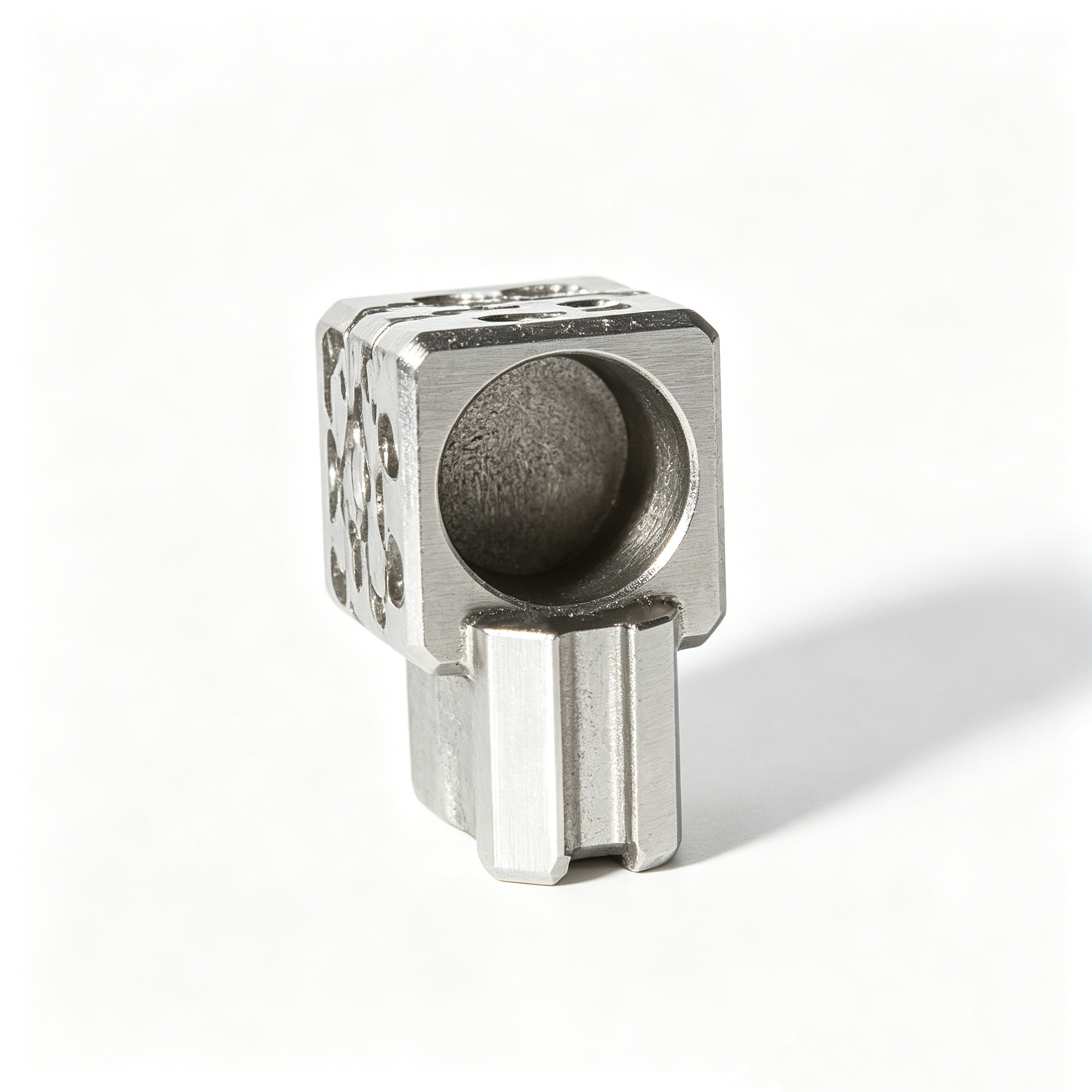
Representative Electrical Terminal Mold Insert Configurations






Related Configurable Families and RFQs








Electrical Terminal Mold Inserts, Reviewed for Manufacture
SUUXIANG helps teams translate drawing requirements into controlled tooling routes, inspection plans, and visible revision decisions.
Drawing-Led DFM Review
We review datums, critical dimensions, tool access, and tolerance risks before quotation or production commitments are made.
Coordinated Process Routes
CNC machining, EDM, grinding, and fitting are planned together to match geometry, access constraints, material condition, and finishing needs.
Critical-Dimension Planning
Inspection priorities are defined around functional dimensions, datum relationships, surface requirements, and mating-component context supplied with your RFQ.
EDM and Grinding Strategy
Electrode needs, wire paths, grinding stock, and heat-treatment sequence are considered early to reduce avoidable rework risks.
Inspection Matched to Order
The inspection method and documentation are aligned with verified order requirements, helping maintain traceability from drawing revision through delivery.
Visible Revision Control
Drawing changes, manufacturing questions, and delivery information remain coordinated so teams can make decisions with current project context.
Drawing-Driven Tooling and Machining Families
Configurable manufacturing categories for connector tooling, mold components, die parts, and custom CNC work—reviewed against drawing, material, quality, and delivery requirements.

CNC Machining Services
Precision CNC machining services for drawing-based parts that require coordinated milling, turning, EDM, grinding, fitting, and inspection. Process routing is reviewed against critical dimensions, material condition, access requirements, quantity, and documentation needs before production commitments are made.
Upload a Drawing
CNC Milling
Custom CNC milling services for prismatic, contoured, and feature-rich components. Drawing review considers datum strategy, tool access, wall geometry, machining allowance, surface requirements, and the relationship between milled features and downstream EDM or grinding operations.
Upload a Drawing
CNC Turning
Precision CNC turning services for rotational parts, threaded features, stepped diameters, and concentric geometries. SUUXIANG reviews critical diameters, runout expectations, datum references, material condition, and any secondary milling, EDM, grinding, or inspection requirements.
Upload a Drawing
5-Axis Machining
5-axis CNC machining supports complex surfaces and multi-angle features where a controlled setup strategy can reduce re-clamping. Feasibility depends on part geometry, tool reach, datum protection, surface requirements, material condition, and the defined inspection approach.
Upload a Drawing
Swiss & Micro Machining
Swiss machining and micro machining support small, detailed components where feature access, concentricity, handling, and inspection require careful planning. Drawings should identify critical diameters, thin sections, threads, surface priorities, material, quantity, and mating-part context.
Upload a Drawing
Wire & Sinker EDM
Wire EDM and sinker EDM services address hardened materials, narrow slots, sharp internal features, fine contours, and geometries with limited conventional tool access. Electrode strategy, wire path, flushing, recast-layer considerations, allowances, and final inspection requirements are reviewed by application.
Upload a Drawing
Precision Grinding
Precision surface and profile grinding is used to control flatness, parallelism, profile, and finished dimensions after machining or heat treatment. Grinding stock, datum sequence, material condition, surface requirements, and measurement method should be agreed before release.
Upload a Drawing
Mold Core & Cavity Inserts
Precision mold core and cavity inserts are configured from drawings for injection tooling and related mold applications. Manufacturing planning addresses steel selection, heat-treatment sequence, cooling or feature access, EDM needs, grinding allowances, critical interfaces, and inspection evidence.
Upload a Drawing
Ejector & Ejection Components
Ejector pins, sleeves, and ejection components are produced to drawing-defined geometry and fit requirements. Review focuses on working diameters, clearance relationships, hardness requirements, surface condition, guidance, stroke-related interfaces, and compatibility with the surrounding mold assembly.
Upload a Drawing
Core Pins, Guide & Locating Components
Core pins, guide pins, and locating components are planned around functional alignment and repeatable fit. Critical details include datum references, mating bores, positional relationships, hardness and finish requirements, wear considerations, and the inspection criteria required for assembly.
Upload a Drawing
Slides, Lifters, Gates & Mold Accessories
Mold slides, lifters, gates, and accessories are configurable tooling components for controlled motion, material flow, and mold assembly functions. Drawings should clarify travel interfaces, shutoff geometry, tolerances, heat treatment, surface condition, and relationships with mating components.
Upload a Drawing
Connector Mold Components
Precision connector mold components support tooling used for connector housings and related molded features. Manufacturing review considers fine pitches, cavity relationships, pin and insert geometry, datum control, material and heat treatment, EDM or grinding route, and inspection documentation.
Upload a Drawing
Stamping Die Components
Precision stamping die components are manufactured from drawing-defined requirements for forming, cutting, guiding, and locating functions. Process planning considers material condition, hardness, clearance relationships, edge condition, grinding stock, EDM strategy, and dimensional verification.
Upload a Drawing
Injection, MIM, CIM & Overmolding Tooling
Injection, MIM, CIM, and overmolding tooling work is evaluated within verified production scope. Drawings and application context help define insert geometry, shrinkage-related interfaces, material selection, surface requirements, molding considerations, and the required route through machining, EDM, grinding, and inspection.
Upload a Drawing
Machining Materials
CNC machining materials are selected from customer requirements and confirmed against part function, machinability, heat-treatment sequence, corrosion needs, and inspection expectations. Material grade, condition, traceability needs, and any substitution restrictions should be provided with the RFQ.
Upload a Drawing
Surface Finishes & Heat Treatment
Surface finishing and heat treatment requirements are reviewed as part of the manufacturing route, not as isolated notes. Specify finish type, roughness or appearance priorities, hardness target where applicable, masking or critical surfaces, post-treatment grinding needs, and documentation requirements.
Upload a Drawing
Quality, Metrology & Documentation
Precision inspection, metrology, and quality documentation are planned around drawing-defined critical dimensions and order requirements. Buyers should identify CTQ features, datums, report format, sampling or full-inspection expectations, material records, revision status, and traceability needs before production.
Upload a Drawing
Prototyping & Low-Volume Production
Rapid prototyping and low-volume manufacturing support drawing-based evaluation, tooling development, engineering changes, and controlled small-batch requirements. A useful RFQ includes quantity, material, critical dimensions, surface and heat-treatment requirements, inspection needs, revision level, and target delivery date.
Upload a DrawingMaterials for Electrical Terminal Mold Inserts

Tool Steel
A versatile choice for cores, cavities, and formed details where balanced machinability and wear resistance are required. Grade, hardness target, grinding stock, and heat-treatment sequence should follow the drawing and application review.

Pre-Hardened Steel
Useful for mold insert structures requiring stable machining after supply and reduced distortion risk from post-machining hardening. It suits moderate-wear tooling features when the required surface condition and service load are clearly defined.

High-Speed Steel
Selected for demanding cutting, punching, or fine formed features where wear resistance is a priority. Its hard machining behavior requires early review of EDM strategy, grinding allowance, heat treatment, and critical edge geometry.

Tungsten Carbide
Applied to high-wear terminal-forming or guide areas where stiffness and abrasion resistance matter. Its brittle nature and specialized grinding or EDM requirements make datum definition, support geometry, and mating-part conditions essential review points.

Stainless Steel
Considered for inserts exposed to moisture, corrosive process conditions, or applications needing corrosion resistance. The selected grade must balance machinability, heat-treatment response, surface finish, and the tooling environment specified in the RFQ.
Electrical Terminal Mold Inserts: Process Routes


Wire EDM
Wire EDM produces narrow slots, sharp internal profiles and difficult-through features where cutter access is limited. The wire path, start-hole strategy and finishing passes are reviewed against drawing datums and critical fit conditions.

Sinker EDM
Sinker EDM addresses deep cavities, fine ribs and internal detail beyond practical milling reach. Electrode design, burn sequence and finishing allowance are coordinated with the required geometry, surface condition and downstream fitting work.


Fitting and Inspection
Fitting and inspection verify mating relationships, critical dimensions and drawing-defined requirements before delivery. The inspection plan follows agreed datums, measurement methods and revision status so documentation matches the ordered electrical terminal mold inserts.
Supporting Components for Electrical Terminal Mold Inserts

Guide Components
Guide pins, bushes and related elements can be reviewed for alignment needs, wear interfaces and assembly clearance within connector tooling and electrical terminal mold insert layouts.

Locating Elements
Locating pins, stops and datum features help establish repeatable relationships between insert, cavity and mating tooling components. Their geometry should be assessed against drawing datums and tolerance stack requirements.

Fastening Hardware
Screws, dowels, retainers and threaded features can be specified with the drawing package to support secure assembly, practical access for maintenance and controlled component replacement.

Ejection Components
Ejector pins, sleeves, return elements and related hardware can be considered where part release, clearance, contact locations and surface sensitivity affect the connector tooling design.

Mold Accessories
Springs, wear plates, slides, lifters and other mold-accessory components can be reviewed as drawing-driven supporting elements when their interfaces influence tool movement, fitting or inspection planning.
About SUUXIANG Electrical Terminal Mold Inserts
SUUXIANG is the public-facing brand of Dongguan SuuXiang Precision Mold Co., Ltd., established in 2010 in Chang’an Town, Dongguan, Guangdong, China. We help global teams turn drawings, models and specifications into inspected custom CNC parts, precision mold components, connector tooling and stamping-die components.
For electrical terminal mold inserts, our work begins with drawing review and DFM discussion. We examine critical dimensions, datums, material and heat-treatment requirements, machining access, EDM or grinding needs, surface priorities and inspection expectations before production commitments are made.
Our difference is disciplined coordination across CNC machining, EDM, precision grinding, fitting and inspection. Rather than treating a quotation as a simple part-price exercise, SUUXIANG keeps revision control, quality requirements and delivery information visible so teams can make informed manufacturing decisions.

Electrical Terminal Mold Inserts: A Supplier Evaluation Checklist
Drawing-First DFM Review
We review electrical terminal mold inserts against the 2D drawing, 3D model, mating context, and stated quality requirements before quotation. The discussion identifies critical dimensions, datum logic, tool access, and risks that could affect machining, fitting, or inspection.
- Confirm critical-to-quality dimensions and functional datums
- Review thin features, corner conditions, and machining access
- Align material, heat treatment, quantity, and revision requirements
- Define open questions before production commitments

EDM Strategy for Fine Features
Where terminal geometry calls for EDM, SUUXIANG plans the process around feature form, access direction, corner definition, and downstream finishing. Electrode and wire-path decisions are reviewed with the drawing requirements so EDM is integrated with CNC machining and grinding allowances.
- Assess wire EDM access for slots, profiles, and narrow features
- Plan electrode geometry for sinker-EDM details where applicable
- Protect datum relationships through machining sequence
- Allow appropriate stock for finishing and grinding

Grinding and Inspection Planning
Precision tooling depends on a controlled finishing route, not a dimensional promise in isolation. SUUXIANG aligns grinding stock, surface priorities, measurement method, and inspection evidence with the order so the final verification addresses the dimensions that matter to the tool function.
- Identify surfaces requiring grinding or controlled finish
- Link inspection points to drawing datums and tolerances
- Clarify reporting and documentation expectations in the RFQ
- Maintain visible revision and delivery coordination

Electrical Terminal Mold Inserts: SUUXIANG vs. a Typical Job-Shop Quote
Compare drawing-led process planning and inspection expectations before you release connector tooling for production.
← Swipe left or right to view →
From Drawing Review to Delivery
A disciplined workflow for electrical terminal mold inserts, with manufacturability, critical dimensions, process routing, inspection, and delivery requirements kept visible throughout the project.
Review Drawings and Requirements
We review drawings, models, material, quantity, application context, target date, and reporting needs to identify critical dimensions, datums, surface priorities, and open questions.
Confirm DFM and Process Route
The team assesses tool access, machining allowance, heat-treatment sequence, electrode strategy, wire paths, grinding stock, and fitting needs before production commitments are finalized.
Machine Core Components
CNC milling, turning, multi-axis, Swiss, or micro-machining operations are selected according to the approved drawing, geometry, material condition, and critical-feature requirements.
Apply EDM and Grinding
Wire EDM, sinker EDM, and precision grinding address fine profiles, inaccessible features, hardened conditions, and finishing allowances using the confirmed process plan.
Inspect Pack and Coordinate Delivery
Finished electrical terminal mold inserts are inspected against the agreed plan; documentation, revision status, protective packing, and delivery coordination are aligned with the order requirements.
Start Your Electrical Terminal Mold Inserts RFQ
Share complete technical inputs early so DFM, process planning, inspection expectations, and delivery coordination can be reviewed before production commitments.
Send Your Drawing Package
Provide the 2D drawing, available 3D model, application context, and mating-component information so the team can assess geometry, datums, and machining access.
Define Material and Quantity
State material, heat-treatment requirements, quantity, target delivery date, and surface priorities to support an appropriate process route and commercial review.
Identify Critical Requirements
Mark critical dimensions, tolerances, surface requirements, datum references, and reporting needs so inspection methods and manufacturing risks are addressed before quotation.
Review DFM and Quotation
Confirm DFM feedback, machining or EDM strategy, grinding allowances, revision status, inspection scope, and quoted assumptions before releasing samples or production.
Coordinate Production and Delivery
After approval, coordinate sampling or production, inspection documentation, revision visibility, and delivery details against the agreed drawing package and project schedule.
Customer Evidence Is Published Only After Verification
Electrical Terminal Mold Inserts: Customer Results and Application Cases
Approved customer testimonial pending SUUXIANG verification. Publish only after the application context, measurable outcome, customer approval, and supporting project records have been confirmed.
Approved customer case pending SUUXIANG verification. Document the drawing revision, critical dimensions, inspection evidence, delivery result, and customer-approved measurable outcome before publication.
Approved customer testimonial pending SUUXIANG verification. Include only substantiated results for electrical terminal mold inserts, with customer authorization and traceable supporting evidence.
Electrical Terminal Mold Inserts FAQ
Practical answers for drawing-driven connector tooling inquiries, from DFM review through inspection and delivery planning.
What files should I send for electrical terminal mold inserts?
Can SUUXIANG manufacture electrical terminal mold inserts from a drawing?
Is there a minimum order quantity for electrical terminal mold inserts?
How should I plan samples and lead time?
Which materials are suitable for connector mold inserts?
Can I request inspection reports for electrical terminal mold inserts?
How are revisions and intellectual property handled?
Can SUUXIANG ship internationally and coordinate delivery?
The Complete Buyer’s Guide to electrical terminal mold inserts
Use this decision framework to specify electrical terminal mold inserts, compare materials and manufacturing approaches, vet capable suppliers, control cost and quality risk, and avoid drawing, tolerance, tooling, and validation mistakes before production.
1. What Are Electrical Terminal Mold Inserts?
Three distinct items are often conflated: the precision mold insert is a hardened, replaceable tooling component; the electrical terminal is the conductive stamped or machined part; and the finished connector is the plastic-overmolded assembly. In insert molding, the terminal is placed in a cavity and resin flows around it to create the integrated product (https://www.layana.com/en/technology/insert-molding).
SUUXIANG treats electrical terminal mold inserts as drawing-controlled tooling parts that locate terminal datum features, form plastic interfaces, support slender contact areas against injection pressure, and protect features during molding and ejection. They are not automatically the terminal or the connector supplied to the end user.
One RFQ should state which item is required: a mold insert, terminals, a complete tool component, or an overmolded connector. Include the 2D drawing and model, terminal geometry and datum scheme, mating context, resin-contact surfaces, critical dimensions, material and heat-treatment requirements, quantity, and inspection evidence needed.
2. Evolution of Electrical Terminal Mold Inserts
1-piece connector assemblies historically depended more heavily on separately made contacts, housings, and later assembly operations; insert molding instead places a preformed terminal in the cavity before resin is injected around it (https://www.layana.com/en/technology/insert-molding). That shift made terminal location, retention features, and molding conditions part of one tooling problem rather than separate downstream tasks.
2 trends now drive tighter insert-tool requirements: connector miniaturization and higher pin counts. Multi-cavity tools and automated insert placement can improve process repeatability, but they also amplify any error in pitch, orientation, carrier handling, gate balance, or cavity-to-cavity variation.
3 sourcing implications follow from that evolution: the insert, resin, mold steel, and inspection plan must be reviewed as a system. Buyers should define datums, critical pin geometry, material and heat-treatment requirements, sampling or inspection evidence, revision status, and automation interface assumptions before approving production tooling.
3. Types of Electrical Terminal Mold Inserts
Six electrical terminal mold insert categories define the tooling scope before steel is released. Classify each by molded function, datum relationship, loading, and expected change frequency.
| Category | Typical Geometry | Selection Trigger |
|---|---|---|
| Core/cavity | Pockets, ribs, shutoffs | Defines housing form |
| Terminal-location | Nests, slots, pins | Contact position matters |
| Guide/alignment | Keys, guide faces | Datum repeatability needed |
| Wear | Replaceable lands, edges | Localized abrasion expected |
| Multi-terminal/lead-frame | Repeated pitch features | Array loading required |
| Prototype/low-volume | Modular simple blocks | Change risk remains |
Forming And Location Inserts

Two primary groups create polymer geometry and hold the terminal during filling. Core and cavity inserts form pockets, ribs, and shutoffs; terminal-location inserts use nests, slots, or pin features when contact position is critical.
Alignment And Wear Inserts

Two service-driven groups control repeatability over production cycles. Guide and alignment inserts establish half-to-half or terminal-to-cavity position; interchangeable wear inserts isolate gates, bearing lands, or abrasion-prone edges for planned replacement.
Array And Prototype Inserts
Two program conditions change the insert architecture. Multi-terminal or lead-frame inserts need repeated pitch features and loading clearance; prototype or low-volume inserts favor simpler, modifiable construction when geometry or demand remains unsettled.
4. Materials for Electrical Terminal Mold Inserts
Material selection for electrical terminal mold inserts is a service-life and molding-stability decision, not a universal grade choice. Resin chemistry, cavity geometry, production volume, terminal tolerances, cooling demand, and operating environment must be reviewed together.
| Material Family | Primary Strength | Key Limitation | Typical Consideration |
|---|---|---|---|
| P20-class steel | Machinability and repair | Lower wear resistance | Moderate-duty cavities |
| H13-type steel | Toughness and thermal fatigue | Requires heat-treatment control | Cyclic thermal loading |
| 420-class stainless | Corrosion resistance and polish | Cost and machining effort | Corrosive resin or humidity |
| Copper alloy | Thermal conductivity | Lower wear resistance | Localized cooling support |
| Nitriding or coating | Surface wear protection | Must suit substrate and geometry | Abrasive resin or sliding contact |
Hardness Versus Toughness
H13-type hot-work steel balances toughness and thermal-fatigue resistance where repeated temperature cycling matters. Hardened cold-work steels raise wear resistance but can require more careful impact and edge-chipping control.
Corrosion And Thermal Control
420-class stainless grades are considered when corrosive resins, humidity, or water exposure make rust prevention important. Beryllium-free copper alloys can move heat quickly near hot spots, but need wear-resistant placement or surface protection.
Finish And Maintenance
P20-class pre-hardened steel is practical for moderate-duty inserts needing machinability and repairability. Polish level, fiber-filled resin abrasion, vent cleanliness, and inspection access should define the maintenance plan before release.
5. Electrical Terminal Mold Inserts: Custom Design Options
Drawing-controlled electrical terminal mold inserts should be customized around functional datums, not nominal dimensions alone. SUUXIANG reviews geometry, process access, and inspection evidence before confirming a route.
| Option | Flexibility | Best Use |
|---|---|---|
| Standard insert | Fixed interfaces | Proven platform |
| Fully custom | Geometry tailored | New terminal layout |
| Prototype tooling | Change-friendly | Early validation |
| Production tooling | Durable interfaces | Controlled release |
Datums And Functional Geometry

Datum A should locate the terminal-support face; B and C should constrain pitch and orientation.
0.02 mm is meaningful only when material, heat treatment, and measurement method are specified.
Tooling Features And Finish

Shutoffs need protected land geometry, while vents and ejection interfaces require clearance and service access.
Interchangeable details, surface finish, and identification marks should support maintenance, revision control, and traceability.
Inputs For DFM Review
2D drawings, 3D models, quantity, resin, terminal layout, and mating context enable actionable DFM.
CTQ dimensions, finish, heat treatment, inspection reports, and target date define the review scope.
6. Critical Construction and Quality Elements
Electrical terminal mold inserts succeed or fail at their datum scheme. Buyers should review the features that locate the terminal, form polymer boundaries, and survive repeated cycling.
Datums And Terminal Location
Primary, secondary, and tertiary datums must locate the insert before cavity steel closes. Uncontrolled seating or concentricity can shift terminals, distort pin pitch, and create inconsistent connector geometry.
- Request a datum-feature callout map
- Check terminal position to functional datums
- Verify concentric features by the specified method
Edges, Clearance, And Venting
Sharp edges require defined breaks or radii where terminals enter, eject, or contact molded resin. Poor clearance can gall steel or damage terminals; inadequate venting can trap gas, cause short shots, or mark surfaces.
- Specify edge-break limits at handling interfaces
- Review shutoff clearance and wear allowance
- Identify vents near end-of-fill regions
Wear, Finish, And Evidence
Wear faces need compatible heat treatment, finish, and lubrication strategy before production release. Ask for material and heat-treatment records, dimensional reports to datums, surface-finish results, assembly fit checks, and revision-controlled inspection plans.
- Heat-treatment certificate or traceable record
- First-article dimensional inspection report
- Assembly and terminal-location verification
7. How to Choose an Insert Manufacturer
Two inputs—a controlled 2D drawing and, when available, a 3D model—should start supplier evaluation. For electrical terminal mold inserts, nominate only after process, inspection, and change-control evidence align with the application.
| Evaluation Area | Ask Before Nomination | Evidence |
|---|---|---|
| Drawing Review | Who owns CTQs and DFM actions? | Marked drawing and action log |
| Materials | How is heat or lot traced? | Certificate linked to order |
| Production Changes | What triggers reapproval? | Revision record and sample approval |
Drawing Review Evidence
2D drawings should trigger documented review of datums, CTQs, tool access, wire paths, electrode strategy, grinding stock, and heat-treatment sequence. Ask who signs off feasibility and closes questions.
Process And Inspection Fit
CNC, wire or sinker EDM, grinding, fitting, and metrology should match each feature—not merely appear on a capability list. Request the inspection method, sampling plan, gauge status, material certificate linkage, and first-article record.
Control After Approval
Prototype support should lead to an approved sample and a revision-controlled production route. Confirm protective packaging, lead-time assumptions, shipment updates, nonconformance containment, root-cause response, and corrective-action closure.
8. Common Electrical Terminal Mold Insert Mistakes
Electrical terminal mold inserts fail most often before machining begins, when functional intent is absent from the RFQ. Treat each drawing release as a manufacturing and assembly-control document, not merely geometry.
Ambiguous Geometry And Datums
2D drawings without datum references or CTQ callouts leave suppliers to infer location priorities. The warning sign is several plausible inspection setups; the consequence is compliant features that do not mate.
Prevent this by identifying primary, secondary, and tertiary datums, then marking functional dimensions and allowable measurement methods.
Material Chosen By Price
Low initial material cost can conceal unsuitable hardness, conductivity, corrosion behavior, or EDM response. The warning sign is a grade named without condition, heat treatment, or application environment; the consequence is premature wear or unstable molding.
Prevent this by specifying material grade, condition, heat-treatment sequence, resin contact, and expected thermal exposure.
Ignored Resin And Interfaces
Resin shrinkage, melt pressure, and thermal cycling can shift insert retention and mating clearances. The warning sign is an interchangeable-part assumption without interface dimensions; the consequence is flash, stress, or assembly interference.
Prevent this by releasing interface control drawings, tolerance stacks, resin information, and mating-part samples before production.
Inspection Without Assembly Validation
Inspection reports cannot prove functional fit when they omit critical dimensions and assembly checks. The warning sign is approval based only on individual-part measurements; the consequence is a late tool correction.
Prevent this by agreeing the inspection plan, report format, sampling requirement, and a trial assembly using representative mating components.
9. Steps from Design Review to Production
A controlled launch for electrical terminal mold inserts converts functional intent into approved, traceable manufacturing data. Each gate needs a named owner, documented release, and a clear rule for stopping changes.
Define And Package Requirements
Gate 1: Engineering defines current path, mating interfaces, retention loads, resin exposure, datums, critical dimensions, and allowable cosmetic limits. Procurement submits the 2D drawing, 3D model, quantity, target date, and revision-controlled RFQ package.
Gate 2: SUUXIANG reviews machining access, EDM strategy, heat-treatment sequence, grinding stock, and inspection feasibility. Open DFM items require engineering disposition before production release.
Approve Manufacturing Evidence
Gate 3: Quality and supplier agree material traceability, hardness or surface requirements, datum-based inspection methods, sampling, and report format. The approved plan must identify every CTQ characteristic and its acceptance evidence.
Gate 4: First articles are measured against the released drawing before tool build proceeds. Engineering validates molding or assembly performance, including terminal location, fit, flash risk, and ejection behavior.
Freeze Revisions And Reorder
Gate 5: Program management freezes the drawing, model, inspection plan, and approved deviations under one revision identifier. Supplier records process route, inspection results, packaging requirements, and delivery commitments against that release.
Gate 6: Repeat orders reference the frozen revision and any approved change notice. Procurement should confirm quantity, delivery need, documentation, and whether application conditions have changed.
10. Electrical Terminal Mold Inserts Pricing and Cost
2 pricing stages should be separated: one-time engineering and setup work, then recurring part cost. Electrical terminal mold inserts with shared datums and straightforward tool access usually need fewer operations than thin, multi-featured inserts requiring EDM, grinding, or fitting.
100% inspection is not interchangeable with sample-based reporting; each changes measurement time, records, and release effort. A credible SUUXIANG quote requires the controlled drawing revision, material and heat-treatment requirements, quantity, critical dimensions, surface requirements, inspection plan, and requested delivery date.
| Cost driver or scenario | Primary cost effect | Quote evidence needed |
|---|---|---|
| Prototype or low quantity | Setup, programming, fixturing, and first-article effort carry more cost per part | Quantity and revision status |
| Repeat or production quantity | Recurring machining, inspection, packing, and yield dominate | Release schedule and batch size |
| Complex geometry | Multi-axis access, electrodes, wire EDM, grinding, and fitting add operations | 3D model, datums, access constraints |
| Tight tolerances or finish | Process sequence, grinding stock, metrology, and acceptance risk increase | Critical dimensions and inspection method |
| Material or heat treatment | Machining behavior, allowance, distortion control, and finishing route vary | Material grade, hardness, treatment sequence |
| Expedited delivery | Capacity coordination and shipment timing may add cost | Required date and delivery location |
Start Your Electrical Terminal Mold Inserts Technical Review
Submit drawings, models, material, quantity, quality priorities, and delivery date for a project-specific RFQ and DFM discussion.