
CP and CPK for Machined Parts: Practical Quality Guidance
Learn how CP and CPK for machined parts inform drawing review, critical-dimension planning, and inspection evidence before production.
How CP and CPK for Machined Parts Reveal Process Capability
Use these measures to separate tolerance width, process spread, and centering before treating capability data as supplier evidence.
Specification Width
Cp compares the drawing tolerance band with observed process variation, showing whether the process spread can fit within specification.
Process Centering
Cpk also considers the process mean, revealing whether variation is centered between limits or drifting toward one specification boundary.
Critical Dimensions
Apply capability analysis to drawing-defined critical dimensions where fit, function, sealing, alignment, or mating performance depends on controlled variation.
Stable Process Evidence
Cp and Cpk are meaningful only when samples represent a stable process, with defined material, setup, measurement method, and revision.
Inspection Context
Review sample size, measurement-system suitability, control limits, and inspection records alongside indexes before comparing supplier capability claims.
Drawing-Led Decisions
Confirm datums, tolerance strategy, machining access, heat-treatment sequence, and inspection priorities before requesting capability evidence for machined parts.
Where Cp and Cpk Matter Most
Process choices, critical dimensions, and inspection evidence for tooling components and custom parts with functional mating requirements.

CNC Machining Services
Precision CNC machining services for drawing-based custom machined parts requiring defined datums, critical dimensions, material control, and inspection planning. Process routes are reviewed against geometry, tolerance stack, surface requirements, quantity, and delivery priorities before production commitments are made.
Upload a Drawing
CNC Milling
Custom CNC milling services support prismatic parts, mold plates, inserts, pockets, channels, and complex feature relationships. Tool access, setup strategy, remaining stock, datum transfer, and inspection approach should be established from the drawing and model.
Upload a Drawing
CNC Turning
Precision CNC turning services support rotational parts such as pins, sleeves, shafts, bushings, and locating features. Diameter relationships, runout, concentricity, thread requirements, surface finish, and mating conditions require clear datums and appropriate measurement methods.
Upload a Drawing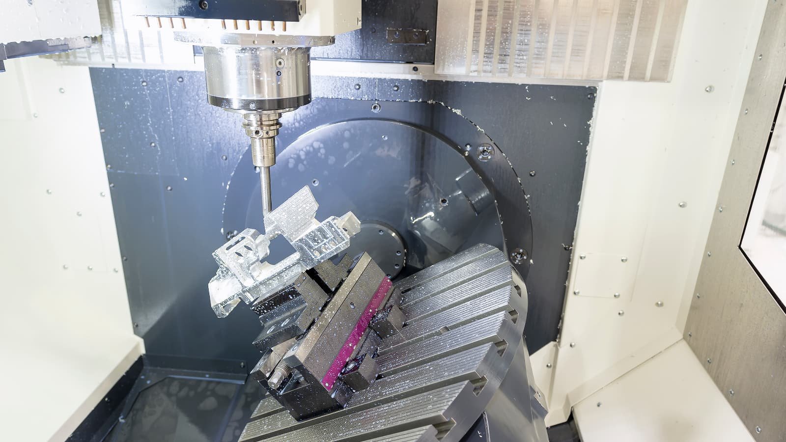
5-Axis Machining
5-axis CNC machining helps reach compound angles, deep features, and multi-face geometries with fewer repositioning risks. Its value depends on cutter access, fixture strategy, allowable tool reach, surface requirements, and the critical features that must remain related.
Upload a Drawing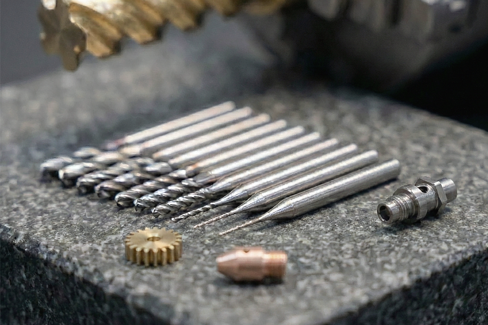
Swiss & Micro Machining
Swiss machining and micro machining support small, slender, and detail-dense components where support, concentricity, burr control, and handling affect results. RFQs should identify critical diameters, feature transitions, materials, quantities, and inspection requirements.
Upload a Drawing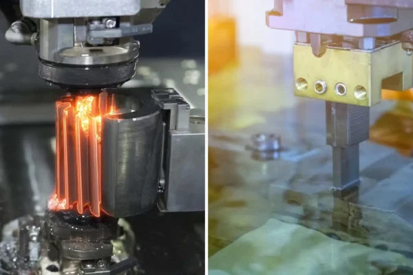
Wire & Sinker EDM
Wire EDM services and sinker EDM services address hardened materials, narrow slots, sharp internal geometry, deep ribs, and features inaccessible to conventional tools. Electrode strategy, wire path, corner conditions, recast-layer expectations, and finishing allowance must be reviewed.
Upload a Drawing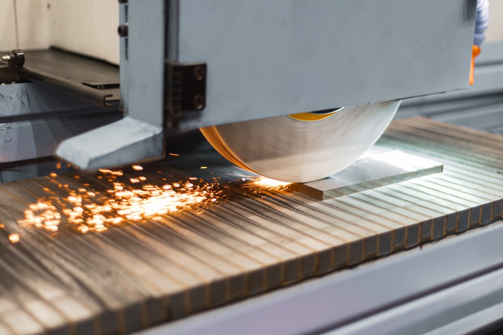
Precision Grinding
Precision surface and profile grinding supports flatness, parallelism, profile accuracy, and controlled final stock on hardened or precision mating components. Grinding allowance, heat-treatment sequence, datum condition, surface requirement, and inspection method determine the process plan.
Upload a Drawing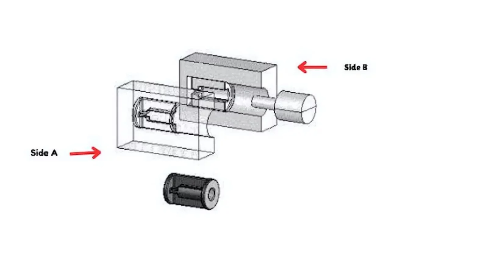
Mold Core & Cavity Inserts
Precision mold core inserts and mold cavity inserts are produced from controlled drawings and functional molding requirements. Critical shutoff areas, cooling or feature access, material and heat treatment, EDM needs, grinding stock, and fitting interfaces should be defined before release.
Upload a Drawing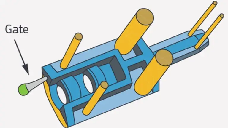
Ejector & Ejection Components
Ejector pins, sleeves, and ejection components require attention to clearance, guidance, hardness, lubrication conditions, and repeated motion. Drawing review should identify functional fits, mating bores, surface requirements, and dimensions requiring documented inspection.
Upload a Drawing
Core Pins, Guide & Locating Components
Core pins, guide pins, and locating components establish feature position and repeatable mold alignment. Diameter, straightness, concentricity, engagement length, material condition, and mating-component tolerances should be considered as an assembly, not as isolated dimensions.
Upload a Drawing
Slides, Lifters, Gates & Mold Accessories
Mold slides, lifters, gates, and accessories require coordinated geometry at moving, sealing, and material-flow interfaces. Review should cover travel direction, clearances, wear surfaces, shutoffs, machining access, EDM requirements, and the inspection references used for fitting.
Upload a Drawing
Connector Mold Components
Precision connector mold components support fine-pitch, high-cavity, and alignment-sensitive connector tooling. Pin geometry, insert relationships, datum strategy, wear areas, material condition, and inspection evidence must reflect the mating and molding function.
Upload a Drawing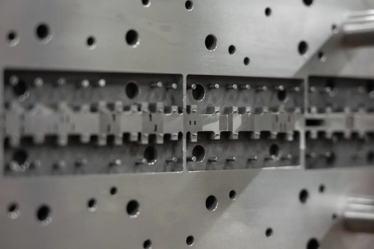
Stamping Die Components
Precision stamping die components include punches, dies, inserts, guides, and locating features that depend on controlled clearance and alignment. Material, heat treatment, edge condition, grinding sequence, EDM strategy, and assembly interfaces should be specified in the RFQ.
Upload a Drawing
Injection, MIM, CIM & Overmolding Tooling
Injection mold components and tooling for MIM, CIM, and overmolding are evaluated within verified production scope. Tooling discussions should identify material behavior, shrinkage considerations, insert interfaces, gates, ejection, critical molded features, and the component-level evidence required.
Upload a Drawing
Machining Materials
CNC machining materials are selected against functional load, corrosion exposure, wear, machinability, heat treatment, and mating conditions. Specify grade, material standard, traceability needs, and any substitute restrictions so the process review reflects the intended application.
Upload a Drawing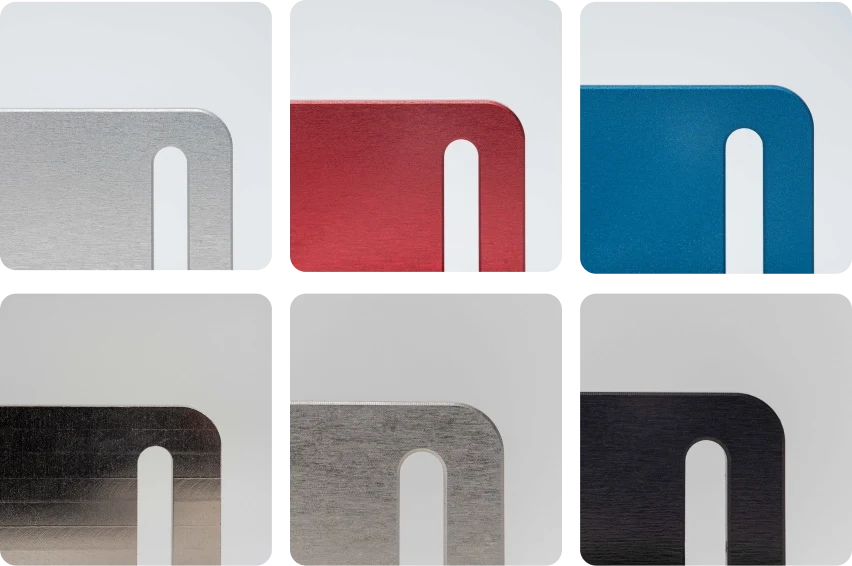
Surface Finishes & Heat Treatment
Surface finishing and heat treatment affect dimensions, wear, corrosion resistance, appearance, and downstream assembly. Requirements should state the specified treatment, finish area, masking needs, hardness or thickness expectations, dimensional priorities, and any post-treatment inspection needs.
Upload a Drawing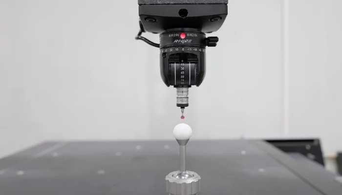
Quality, Metrology & Documentation
Precision inspection, metrology, and quality documentation are planned around critical-to-quality dimensions, datums, and agreed acceptance criteria. Useful RFQs identify reporting needs, sampling expectations, revision status, material records, and any customer-specific measurement method.
Upload a Drawing
Prototyping & Low-Volume Production
Rapid prototyping and low-volume manufacturing support design validation, bridge requirements, fixture development, and controlled small-batch supply. Quantity, revision maturity, material, critical dimensions, post-processing, inspection level, and target date guide an appropriate manufacturing route.
Upload a DrawingBuild CP and CPK for Machined Parts Evidence
Review Datums and CTQs
Meaningful capability evidence begins with the drawing. SUUXIANG reviews functional datums, critical-to-quality dimensions, geometric tolerances, surface requirements, and mating relationships before deciding whether a Cp or Cpk study can represent the actual manufacturing risk.
- Confirm datum references and measurement orientation
- Identify dimensions that affect fit, sealing, or alignment
- Separate critical features from general tolerances
- Clarify revision status and applicable specifications

Plan the Process Route
A capability index is only useful when the process route is stable and appropriate for the feature. CNC machining, EDM, grinding, heat-treatment sequence, and fitting requirements must be considered together, including access limits, machining allowance, and likely sources of variation.
- Match machining methods to feature geometry
- Define EDM, wire path, or electrode needs
- Reserve grinding stock where finishing requires it
- Assess heat treatment before final sizing

Select the Inspection Method
Cp and Cpk for machined parts depend on measurement data that is relevant, repeatable, and traceable. The inspection plan should define instruments, datum setup, sampling logic, reporting requirements, and how measured values will be tied to the approved drawing revision.
- Choose measurement methods suited to tolerance risk
- Document fixture or datum setup requirements
- Align sampling with the agreed inspection plan
- Link reports to part and drawing revisions
A Drawing-Led Process for CP and CPK for Machined Parts
Submit the information needed to align critical dimensions, sampling, inspection methods, and capability-reporting expectations before production planning begins.
Share the Drawing Package
Provide the current 2D drawing, 3D model when available, revision level, material, heat-treatment requirements, quantity, and target delivery date.
Identify Critical Dimensions
Mark functional dimensions, datums, tolerance priorities, surface requirements, and mating relationships so capability discussion focuses on the features that matter.
Define Sampling Expectations
State prototype, first-article, or production sampling needs, lot quantities, and whether CP and CPK evidence is required for designated dimensions.
Align Inspection Reporting
Confirm measurement methods, report format, traceability needs, and acceptance criteria before SUUXIANG plans machining, EDM, grinding, and final inspection.
Cp and Cpk for Machined Parts: What Credible Evidence Includes
Compare drawing-led capability planning and traceable records with capability claims that lack defined supporting evidence.
← Swipe left or right to view →
CP and CPK for Machined Parts: Frequently Asked Questions
Practical guidance for interpreting capability data before it becomes a sourcing requirement.
What are Cp and Cpk for machined parts?
What Cp and Cpk values should I require for machined parts?
Can Cp and Cpk for machined parts be quoted before production?
How many samples are needed for Cp and Cpk studies?
Does a high Cp guarantee that machined parts meet specification?
How does the measurement system affect Cp and Cpk results?
Can Cp and Cpk be used when machined-part data are not normally distributed?
When should Cp and Cpk for machined parts influence supplier selection?
Upload Your Drawing for CP and CPK Review
Share your drawing, material, quantity, quality priorities, and delivery requirements so SUUXIANG can assess critical dimensions and inspection planning.