
Engineering article
Designing Lightweight Pockets in CNC Parts
Lightweight pockets should be designed as controlled structural features, not as empty volume removed wherever possible. A practical approach begins with load paths and boundary conditions, then balances wall stability, corner geometry, tool access, fixturing, inspection, and material behavior. Clear drawings and a disciplined pre-quote review reduce uncertainty before machining begins.
On this page
Start With the Structural Job
A pocket is useful when it removes material that contributes little to the part’s intended structural work. That assessment cannot come from a weight target alone. Identify where force enters the component, how it is supported, which faces locate mating parts, and where stiffness matters most. A pocket placed across a load path can make a part less predictable even when the remaining wall appears visually substantial.
Separate primary load-carrying regions from regions that mainly provide enclosure, clearance, or local mass. Flanges around fasteners, bearing seats, sealing lands, threaded interfaces, and datum surfaces often need special attention because their function depends on geometry as well as strength. If operating loads are variable, include the relevant load cases and restraint assumptions in the engineering record. The drawing or engineering agreement should define the governing acceptance criteria.
- Map applied loads, reaction points, and attachment features before sketching pockets.
- Protect functional interfaces with deliberate local material and transition geometry.
- Use analysis, testing, or established engineering practice when the consequence of deflection is significant.
Choose Pocket Topology Deliberately
Pocket geometry changes the route that forces take through a part. A broad, shallow recess may preserve a more continuous section than a narrow, deep channel, while a ribbed pattern can retain directional stiffness where it is needed. The preferable arrangement depends on bending direction, torsional demand, vibration exposure, and the orientation of connected features. Symmetry can help, but it is not automatically the best response to an asymmetric load.
Avoid treating a pocket floor as an isolated sheet. Its behavior is tied to the surrounding rim, ribs, fastener pattern, and transitions into thicker zones. Smooth changes in section reduce abrupt stiffness changes and can improve the clarity of machining paths. Where repeated pockets are intended as a pattern, identify whether they are cosmetic, clearance-related, or structurally significant; that distinction affects how closely their position and shape should be controlled.
- Use ribs when a web must carry load in a known direction.
- Prefer coherent material islands over arbitrary leftover shapes.
- Keep transitions understandable enough to inspect and revise.
| Pocket approach | Useful when | Design question to resolve |
|---|---|---|
| Open shallow recess | Material can be removed without creating a slender unsupported web | Does the remaining floor retain the required stiffness across its span? |
| Ribbed pocket | Directional bending or torsion needs a defined load path | Which rib orientation follows the force flow and remains accessible to machining? |
| Deep cavity | Internal clearance or package volume drives the feature | Can wall stability, tool reach, chip removal, and workholding be addressed together? |
| Multiple small pockets | Local reductions are preferable to one large flexible area | Are the intervening lands functional, structural, or merely difficult-to-machine remnants? |
Make Geometry Machining-Aware
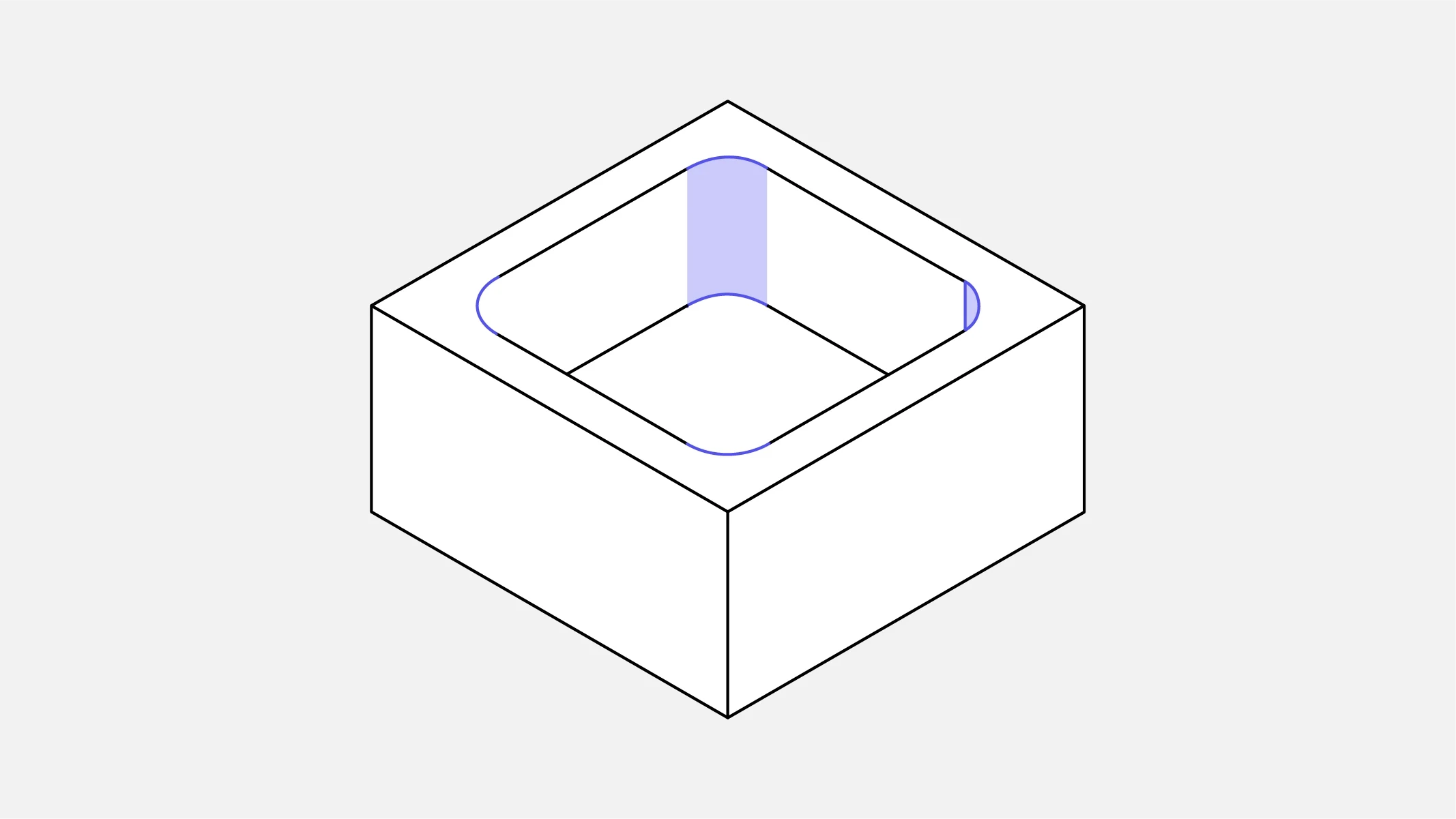
The cutter has a finite diameter, length, and reachable path. Internal corners therefore require radii or deliberate relief geometry; a sharp inside corner on a drawing can create unnecessary secondary operations or an unresolved mismatch with the mating part. Choose corner conditions based on assembly clearance and the intended machining method, then communicate them explicitly. Do not leave a nominally sharp corner to be interpreted as an informal requirement.
Depth relative to opening width influences cutter selection, rigidity, cycle planning, and surface consistency. Very narrow or deep pockets can require longer tools, which may increase sensitivity to cutting conditions and vibration. Tall thin walls can also move during material removal or release stress after machining. A process plan should determine the workable sequence, but designers can reduce risk by allowing sensible access, avoiding trapped regions, and retaining stable support where it is needed.
- Specify internal radii or relief features at interfaces that need clearance.
- Provide a clear tool approach where a floor or sidewall is functionally important.
- Consider chip evacuation and clamping access when cavities become deep or enclosed.
Account for Material Response
Material selection affects more than mass. Modulus, strength, thermal behavior, corrosion environment, surface requirements, and the intended manufacturing route can all change the pocket design. Two lightweight metal choices may require different web proportions, fastening details, finishing allowances, or machining strategy because they respond differently under load and during cutting. Selection should follow the specified material grade and the application’s functional requirements, not a broad material label.
Residual stress and stock form can matter when pockets remove material unevenly from one side of a part. Distortion risk depends on the starting condition, geometry, removal sequence, and any applicable stress-relief approach. Where flatness, alignment, or a critical bore relationship must be preserved, communicate those requirements early so the process plan can address them. A drawing, applicable standard, or engineering agreement should control material condition and any required verification.
- Name the material grade, temper or condition when applicable, and permitted substitutions.
- Connect corrosion protection and finishing requirements to critical mating or datum surfaces.
- Flag distortion-sensitive interfaces before quotation rather than after a pocket layout is fixed.
Plan Sequence and Workholding
A lightweight pocket may be easy to model yet awkward to hold after material removal. Early roughing can reduce stiffness before later operations establish precision features, while clamping directly on thin walls can affect form or leave inaccessible areas. The manufacturing sequence should retain enough support for critical operations and identify when a part must be repositioned. Designers do not need to prescribe every setup, but they should avoid geometry that assumes unsupported precision.
Provide usable external reference surfaces where possible, especially when a pocketed side must be machined while the opposite side contains delicate features. Datum choices should reflect the part’s functional assembly, then be practical to establish during manufacture and inspection. If temporary tabs, sacrificial stock, or staged machining would affect a nonfunctional region, allowing such options in the design discussion can expand feasible process plans without changing the final function.
- Review which surfaces can support clamping before walls become thin.
- Keep critical dimensions related to functional datums, not arbitrary pocket edges.
- Ask how the part may be repositioned when features exist on multiple faces.
Hand Off Dimensions for Inspection
Pocket drawings should distinguish functional dimensions from dimensions that only describe appearance. State the floor depth, wall locations, rib widths, radii, and any critical local thicknesses that control fit or structural behavior. Apply tolerances where their variation changes function, and avoid assigning the same narrow tolerance to every feature by habit. General tolerances can cover noncritical geometry when they are compatible with the design intent and relevant drawing practice.
Inspection is easier when datum references are stable, accessible, and connected to assembly. A coordinate scheme may be appropriate for patterned pockets, while profile control may better express a shaped wall relative to functional datums. Surface texture requirements should be used where they serve sealing, contact, fatigue, coating, or another stated function. The drawing and inspection plan should identify the governing standard, measuring method when necessary, and any feature that needs recorded results.
- Identify critical floor, wall, and interface features with functional rationale.
- Establish datums from assembly relationships before choosing coordinate dimensions.
- Use profile, position, flatness, or other controls only where they express an actual requirement.
Run a Pre-Quote Design Review
Before seeking a quotation, consolidate the information that determines whether the pocket concept is producible and verifiable. Supply the current model and drawing, but also explain the part’s intended duty, production context, material requirement, finish, and critical interfaces. A concise note about expected loads or allowable movement can be more valuable than an unexplained request to make the part lighter. If the design is still exploratory, mark the requirements that remain open.
Invite focused feedback on access, workholding, corner conditions, stock choice, sequencing, and inspection. That conversation is most useful before a release locks in dimensions that conflict with the manufacturing route. Treat suggested changes as engineering decisions: compare their effect on load paths, mating geometry, and verification rather than accepting or rejecting them solely by appearance. Final requirements should be captured in the controlled drawing, revision record, or engineering agreement.
- Provide a revision-controlled CAD model and drawing.
- List material grade or condition, finish, quantity context, and all critical interfaces.
- State the controlling datums, tolerances, and inspection expectations.
- Ask for feedback on tool reach, fixture access, stability, and measurement before release.
Questions engineers ask
How thin should a pocket floor or wall be?
There is no universal thickness suitable for every CNC part. The answer depends on material grade and condition, unsupported span, loads, fastening, vibration, machining access, distortion sensitivity, and the required tolerance. Define the functional requirement first, then establish the geometry through analysis, prior validated practice, testing, or an engineering agreement.
Are rounded internal corners always preferable?
They are usually more compatible with conventional milling because cutters produce radiused internal corners. The required radius still depends on assembly clearance, tool access, load transfer, and the drawing’s function. If a mating component requires clearance, specify a compatible corner radius or a purposeful relief feature rather than relying on an unspecified sharp corner.
What information should accompany a pocketed-part quote?
Provide the revision-controlled model and drawing, material grade or condition, finishing requirements, quantity context, critical dimensions and datums, applicable standards, and relevant assembly or load information. Also identify features whose form, location, or surface condition controls function, so workholding and inspection can be considered before the process plan is finalized.
References and further reading
These resources explain related design and manufacturing principles. Project limits, acceptance criteria and process choices must be agreed against the current drawing.
Publication note: this article is general design guidance, not a material specification, a certified inspection report or a guarantee of process capability.
Turn the drawing into a clear manufacturing brief.
Share the current drawing, material, finish and inspection requirements for a project-specific discussion.