
CNC Machined Clevises, Reviewed Before Production
Send your drawing for CNC machined clevises with DFM, critical-dimension review, process planning, and inspection aligned to your order requirements.
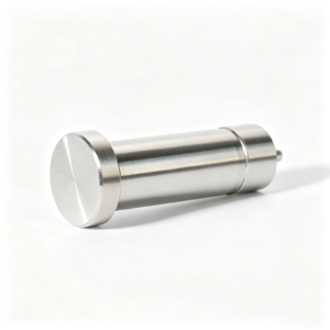
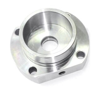
Representative Precision Components and Tooling





Related Drawing-Based Manufacturing Categories







Why Engineering Teams Specify SUUXIANG for CNC Machined Clevises
Drawing-driven review and controlled manufacturing planning for clevis parts where fit, alignment, and documentation matter.
Drawing Review First
We review drawings, models, material requirements, quantities, and application context before committing to a quotation or production route.
Practical DFM Input
Early DFM discussion identifies tool access, slot geometry, thread details, datum choices, and features that may affect manufacturability.
Process Route Planning
CNC machining, EDM, grinding, fitting, and finishing are considered together when part geometry and critical features require coordinated processing.
Critical Dimension Focus
Inspection planning centers on specified critical dimensions, datums, surface requirements, and the measurement methods appropriate to the order.
Revision Visibility
Clear revision, inspection, and delivery information helps engineering, quality, and procurement teams maintain alignment throughout the manufacturing workflow.
Precision Part Families and Process Routes
Explore configurable manufacturing categories built around drawing review, critical dimensions, process planning, inspection requirements, and controlled revision management.

CNC Machining Services
Precision CNC machining services for drawing-based components requiring coordinated milling, turning, EDM, grinding, fitting, and inspection. RFQ review identifies critical dimensions, datums, material requirements, surface priorities, quantity, and the process route appropriate to the part.
Upload a Drawing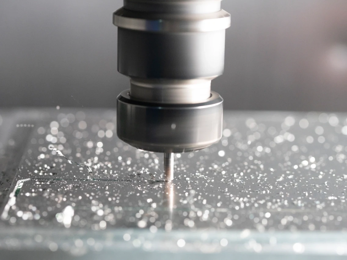
CNC Milling
Custom CNC milling services for prismatic parts, plates, inserts, and features requiring controlled tool access. Drawing review considers datum strategy, pocket depth, wall geometry, machining allowance, surface requirements, and inspection points before machining is committed.
Upload a Drawing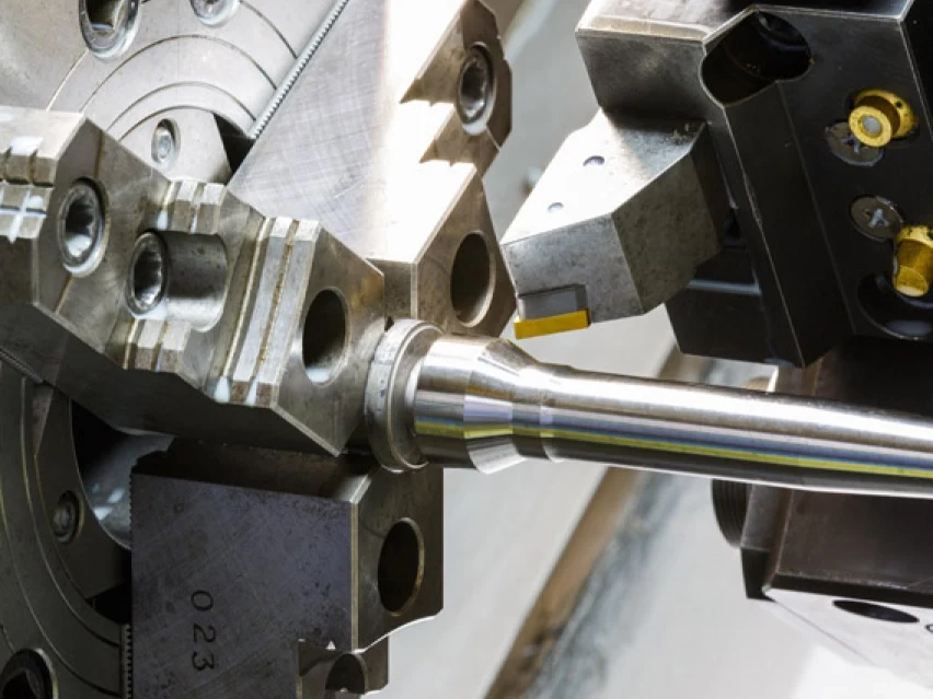
CNC Turning
Precision CNC turning services for shafts, pins, sleeves, bushings, and rotational features. The process route is assessed against concentricity, runout, thread details, material condition, secondary operations, and the dimensional relationship between turned and milled or ground features.
Upload a Drawing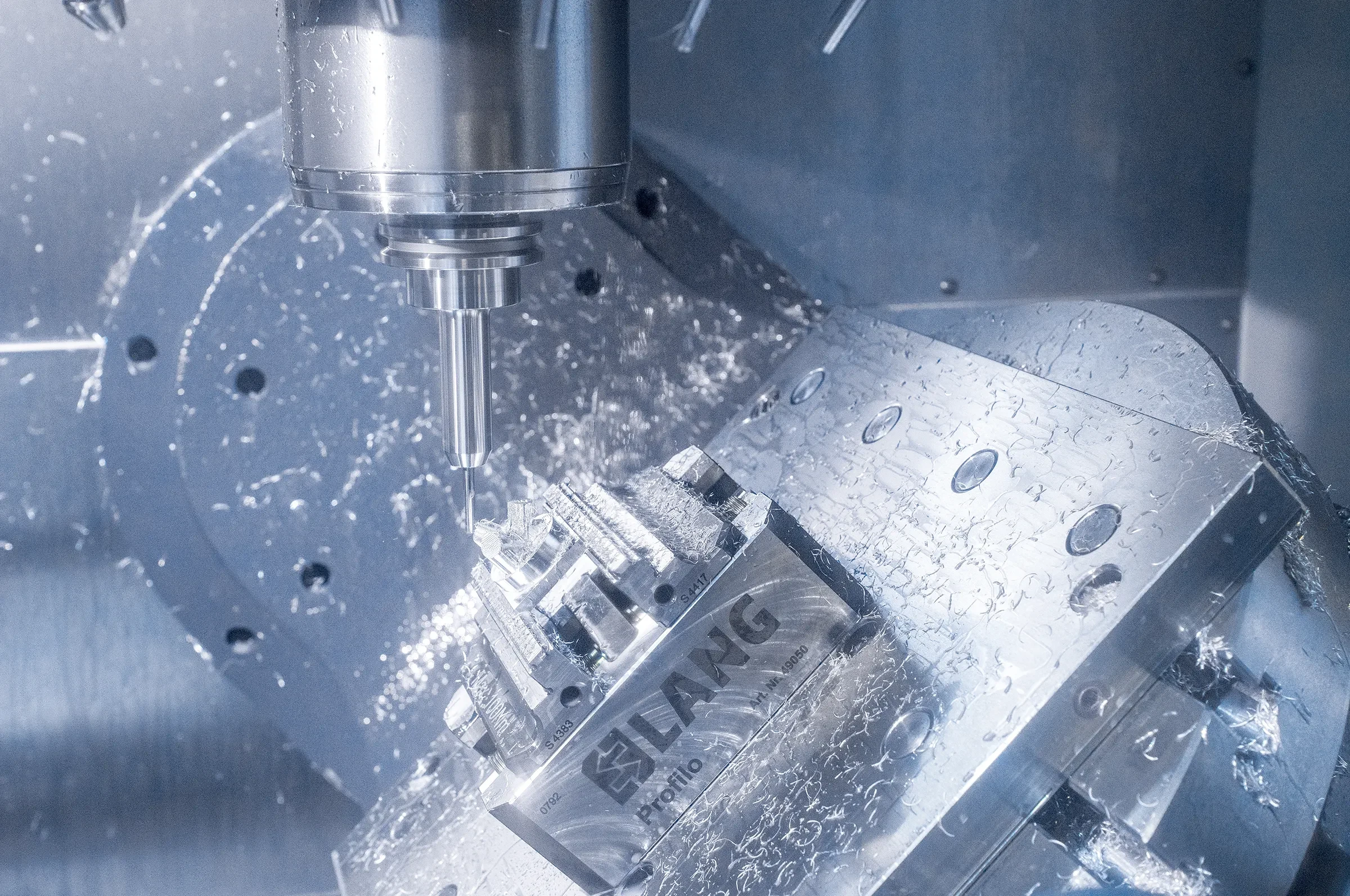
5-Axis Machining
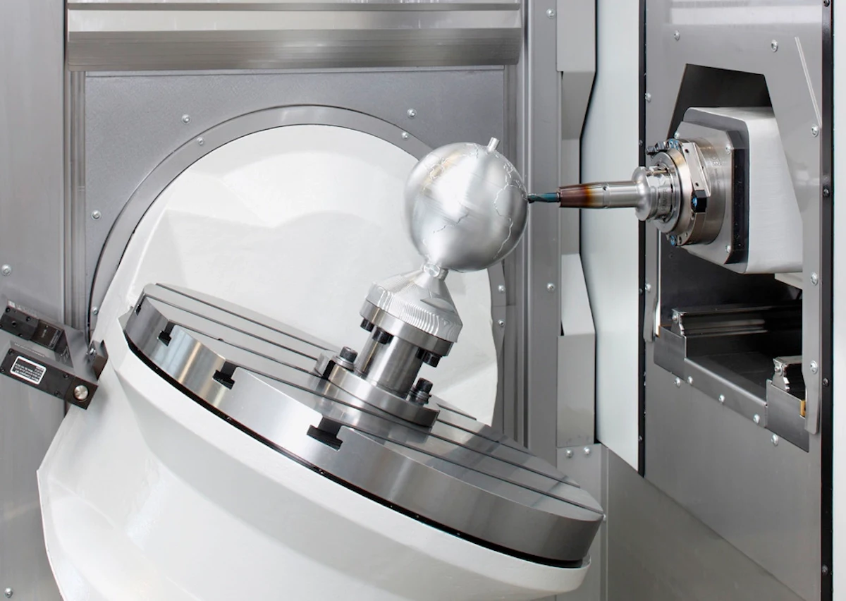
5-axis CNC machining for complex contours, angled features, and multi-face components where setup strategy affects accuracy and handling. SUUXIANG reviews tool approach, fixture access, datum transfer, feature relationships, and inspection feasibility before selecting a machining route.
Upload a Drawing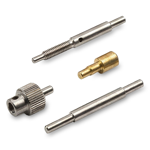
Swiss & Micro Machining
Swiss machining and micro machining for small, slender, or detail-intensive components where support, tool geometry, and handling affect dimensional control. Drawings should identify critical diameters, length-to-diameter relationships, material, burr expectations, and measurement requirements.
Upload a Drawing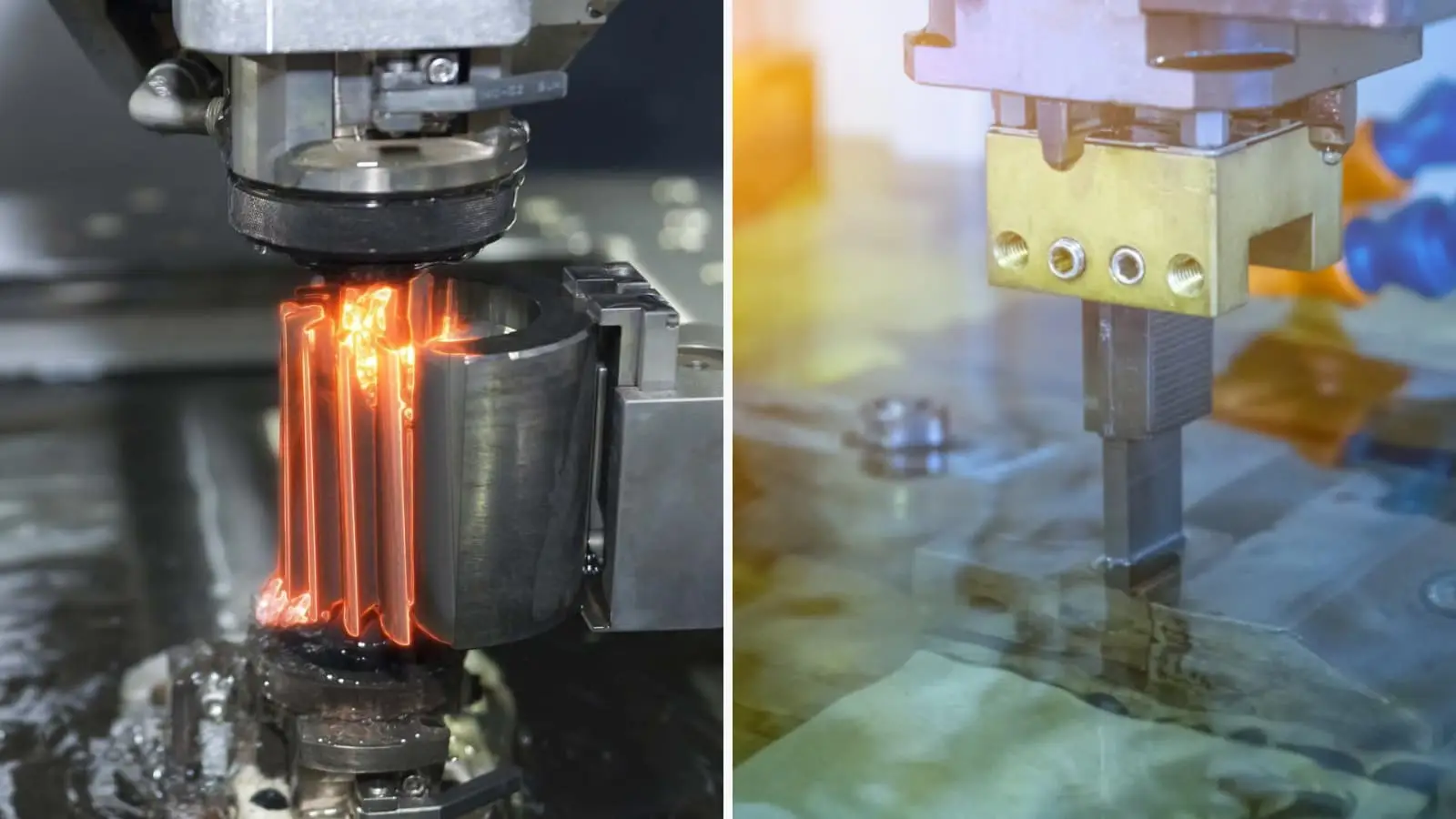
Wire & Sinker EDM
Wire EDM and sinker EDM services for hardened features, narrow slots, sharp internal geometry, deep cavities, and profiles beyond conventional tool access. Planning addresses wire path or electrode strategy, corner requirements, recast-layer considerations, finishing passes, and subsequent inspection.
Upload a Drawing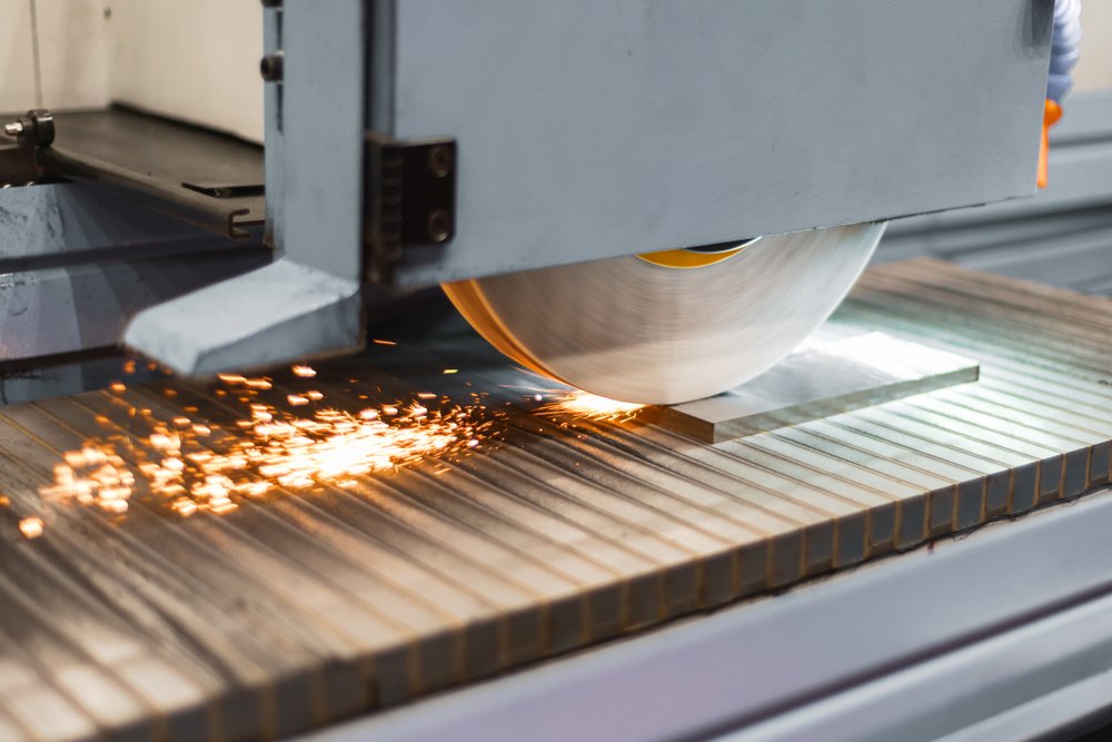
Precision Grinding
Precision surface and profile grinding for flatness, parallelism, profile control, and finished dimensions after machining or heat treatment. A workable plan defines grinding stock, datum condition, material state, surface requirement, and the inspection method for critical features.
Upload a Drawing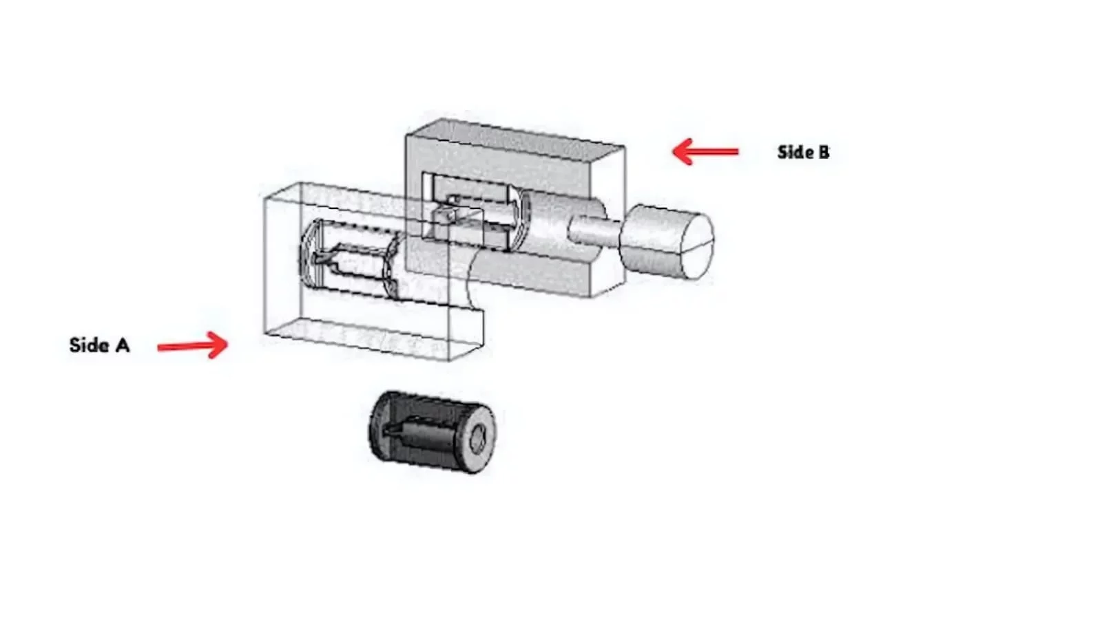
Mold Core & Cavity Inserts
Precision mold core and cavity inserts manufactured from customer drawings for molding-tool applications. Review focuses on parting-line interfaces, cooling or feature access, steel and heat-treatment requirements, EDM strategy, grinding stock, critical cavity geometry, and mating-component relationships.
Upload a Drawing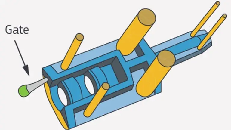
Ejector & Ejection Components
Ejector pins, sleeves, and ejection components for mold assemblies requiring controlled fit, movement, and wear considerations. Drawings should clarify diameters, clearance relationships, surface condition, heat treatment, stroke-related geometry, and inspection priorities for mating features.
Upload a Drawing
Core Pins, Guide & Locating Components
Core pins, guide pins, and locating components produced to support repeatable mold alignment and feature formation. Manufacturing review considers fit class, concentricity, hardness condition, datum relationships, retention details, and how each component interfaces with the surrounding mold assembly.
Upload a Drawing
Slides, Lifters, Gates & Mold Accessories
Mold slides, lifters, gates, and accessories configured from drawings for moving, guiding, feeding, and supporting mold functions. Review addresses travel and interference risks, mating surfaces, wear areas, tool access, heat-treatment sequence, and dimensional checks needed for assembly.
Upload a Drawing
Connector Mold Components
Precision connector mold components for tooling that forms closely spaced, detail-sensitive connector features. Engineering review considers pin or cavity geometry, datum consistency, EDM and grinding needs, wear conditions, mating interfaces, and inspection evidence required for the specified application.
Upload a Drawing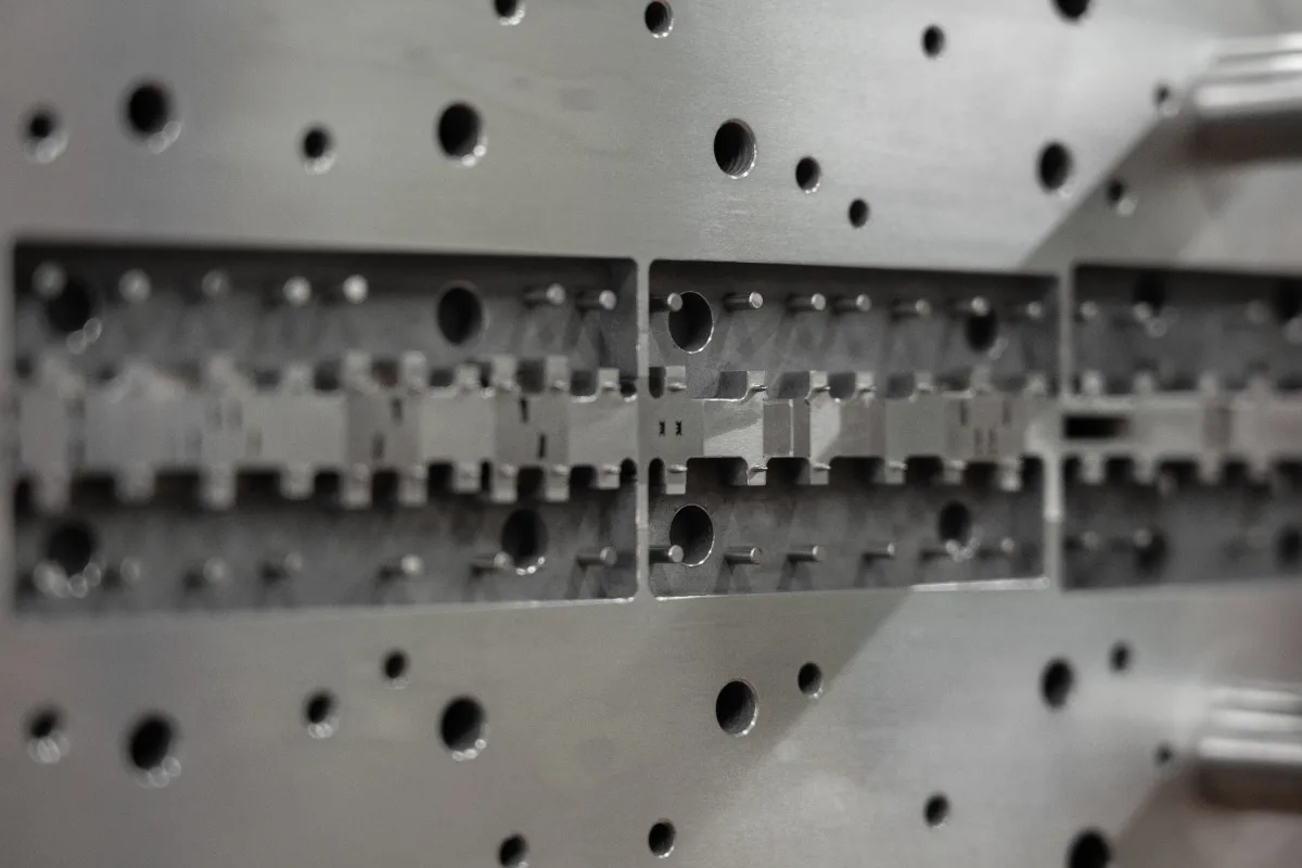
Stamping Die Components
Precision stamping die components for cutting, forming, guiding, and supporting die operations. Drawings are reviewed for punch and die relationships, clearance-sensitive features, material condition, heat treatment, grinding requirements, assembly interfaces, and critical dimensional documentation.
Upload a Drawing
Injection, MIM, CIM & Overmolding Tooling
Injection, MIM, CIM, and overmolding tooling components produced within verified project scope. Feasibility depends on the supplied drawing, molding application, material requirements, shrinkage-related design inputs, gating or interface details, tooling geometry, and agreed inspection plan.
Upload a Drawing
Machining Materials
CNC machining materials selected against drawing requirements, part function, machinability, heat-treatment sequence, corrosion exposure, and inspection needs. Provide the specified grade, material standard, condition, traceability expectations, and any approved alternatives during RFQ review.
Upload a Drawing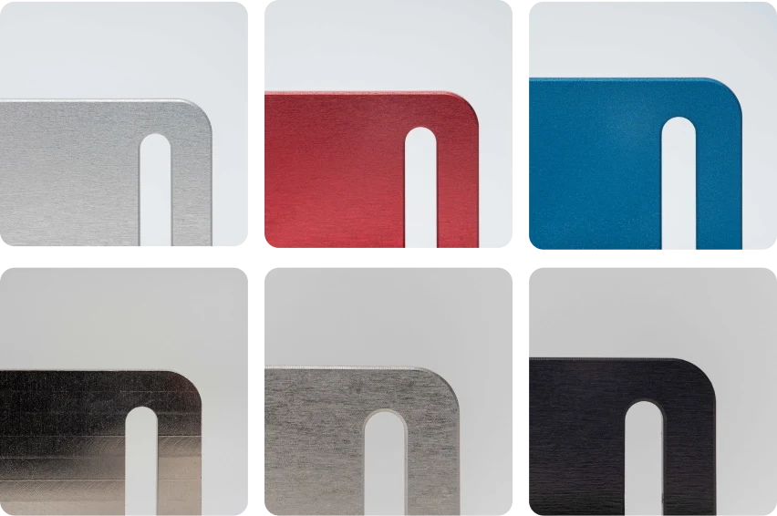
Surface Finishes & Heat Treatment
Surface finishing and heat treatment planned as controlled steps that affect dimensions, wear, corrosion behavior, and appearance. Specify the required finish or treatment, applicable standard, coverage areas, masking needs, post-process tolerance priorities, and any reporting requirements.
Upload a Drawing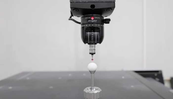
Quality, Metrology & Documentation
Precision inspection, metrology, and quality documentation aligned with the drawing and verified inspection plan. Confirm critical dimensions, datum references, sampling or full-inspection expectations, report format, revision status, material evidence, and any customer-specific traceability requirements before production.
Upload a Drawing
Prototyping & Low-Volume Production
Rapid prototyping and low-volume manufacturing for engineering validation, tooling development, replacement components, and controlled early production. A useful RFQ includes drawings or models, material, quantity, critical features, quality documentation needs, target delivery date, and revision information.
Upload a DrawingMaterial Options for CNC Machined Clevises
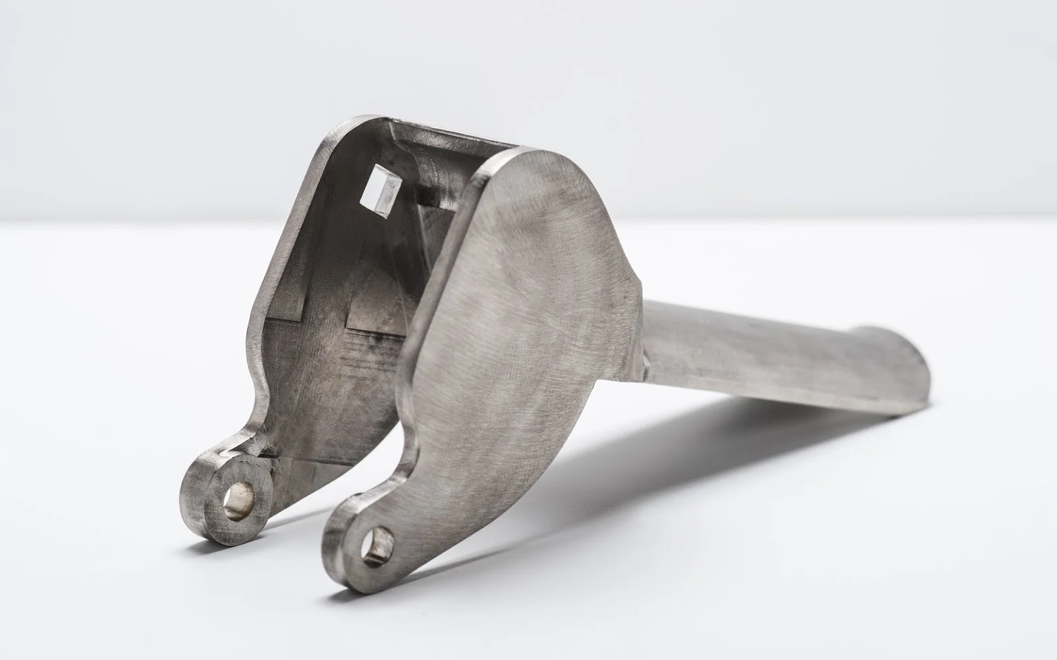
Carbon Alloy Steel
A practical choice for clevis bodies requiring strength, threaded features, or wear resistance. Grade selection, heat treatment, coating needs, and machining allowance should be reviewed together with the drawing’s critical dimensions.
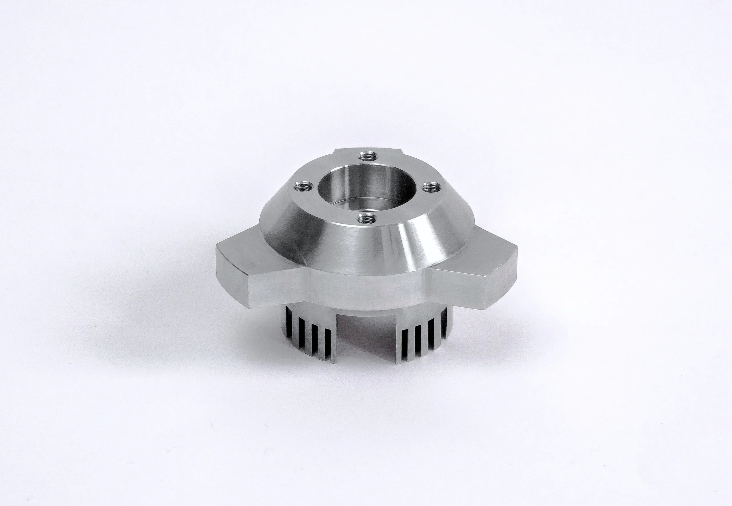
Stainless Steel
Specified where corrosion resistance, cleanability, or environmental exposure drives the material decision. Clevis geometry, thread condition, surface finish, and potential distortion after machining require review against the intended service environment.
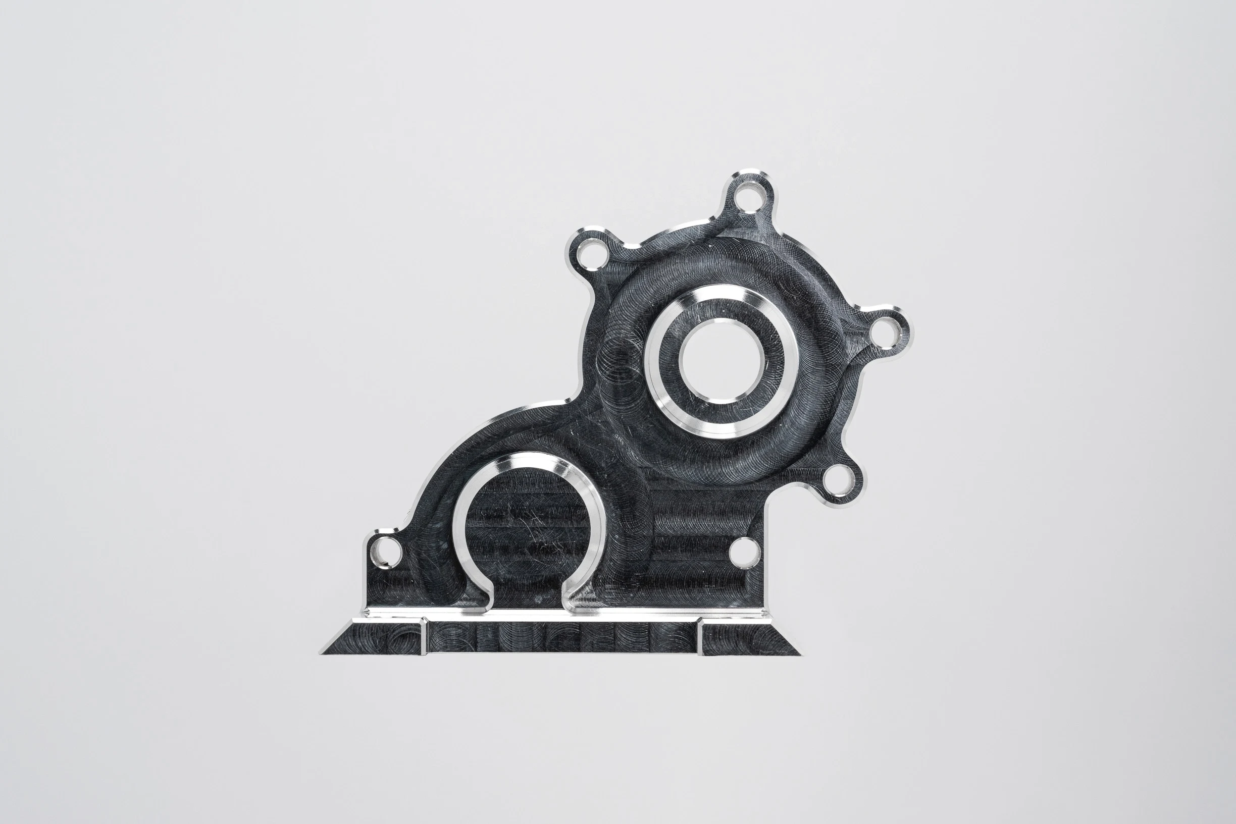
Aluminum Alloys
Useful when lower component mass and corrosion resistance are priorities. Alloy and temper affect machining behavior, thread design, finish selection, and stiffness, so mating loads and any anodizing requirement should accompany the RFQ.
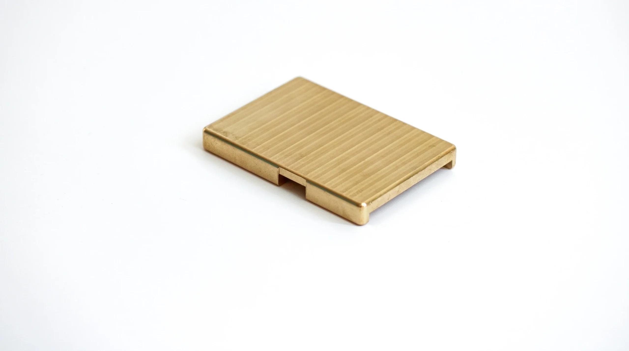
Brass Copper Alloys
Considered for applications needing machinability, conductivity, or particular corrosion behavior. The selected alloy, bearing contact, thread form, and surface-finish expectations should be defined before production planning for a clevis component.
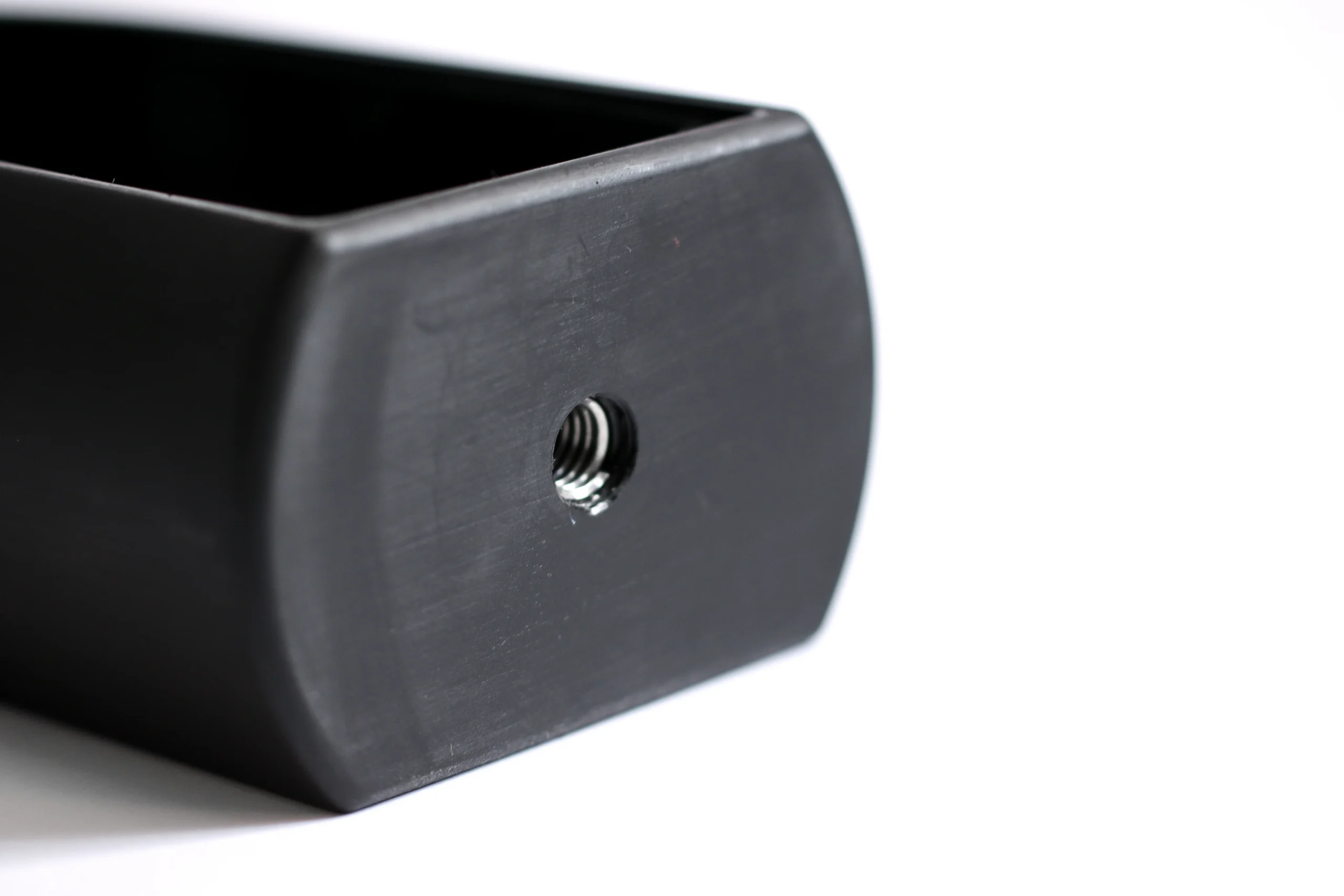
Engineering Plastics
Suitable for selected low-load, insulating, or corrosion-sensitive clevis applications. Polymer grade, operating temperature, moisture exposure, tolerance sensitivity, and reinforcement must be assessed because machining response differs substantially from metal components.

Customer-Specified Materials
Customer-designated metals or engineered materials can be evaluated from the drawing and specification package. Include grade, condition, heat treatment, traceability needs, quantity, application context, and inspection requirements for project-specific review.
CNC Machined Clevises: Machining and Precision Finishing
CNC Milling
CNC milling produces fork profiles, mounting faces, slots and cross-holes from drawing-defined datums. Tool access and workholding are reviewed early to support stable feature relationships and a controlled machined finish.
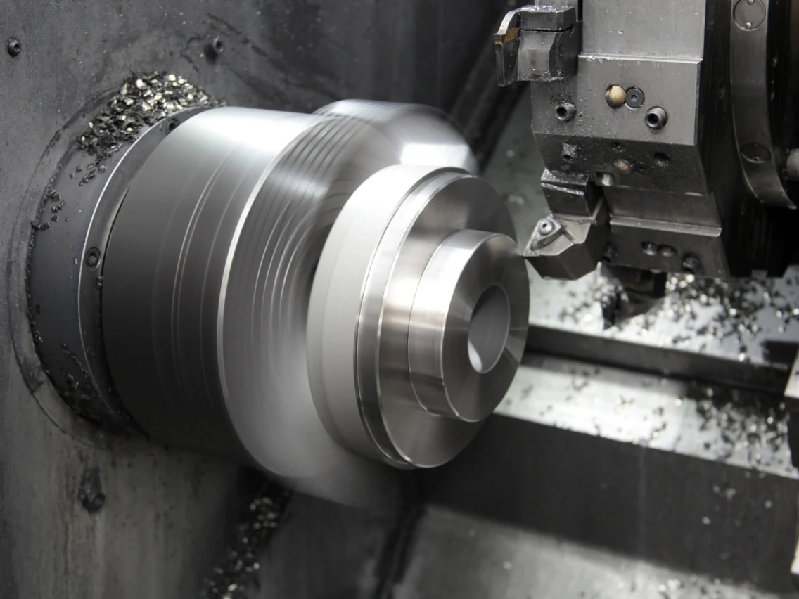
CNC Turning
CNC turning prepares rotational diameters, shoulders and concentric reference features for clevis bodies or related pins. It can establish an efficient blank condition before milling, drilling or subsequent precision finishing.
Wire EDM
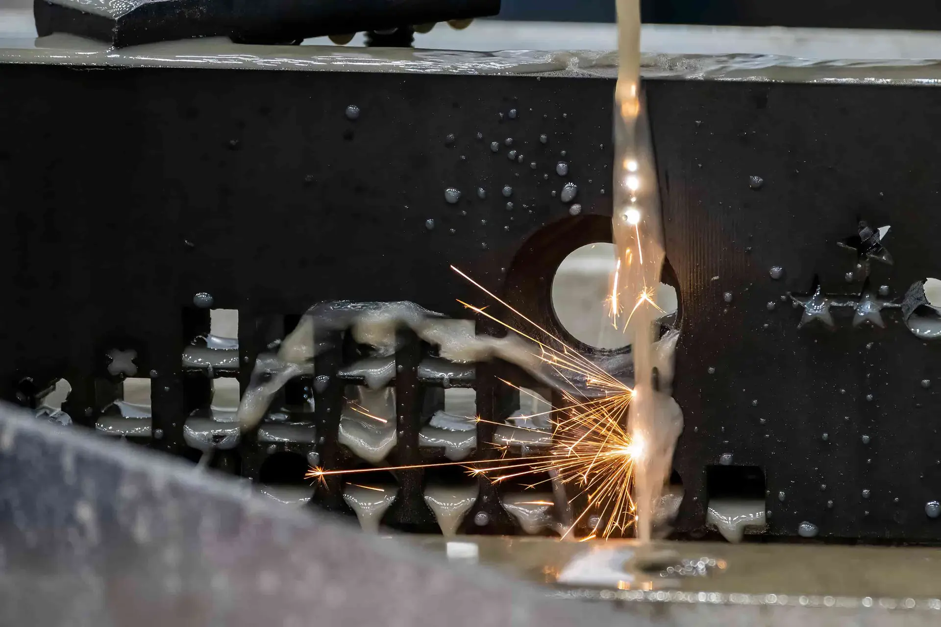
Wire EDM supports narrow slots, internal profiles and hardened-workpiece features where conventional cutter access or force may create risk. Wire path, start-hole location and finish requirements should be aligned with the drawing datums.
Sinker EDM
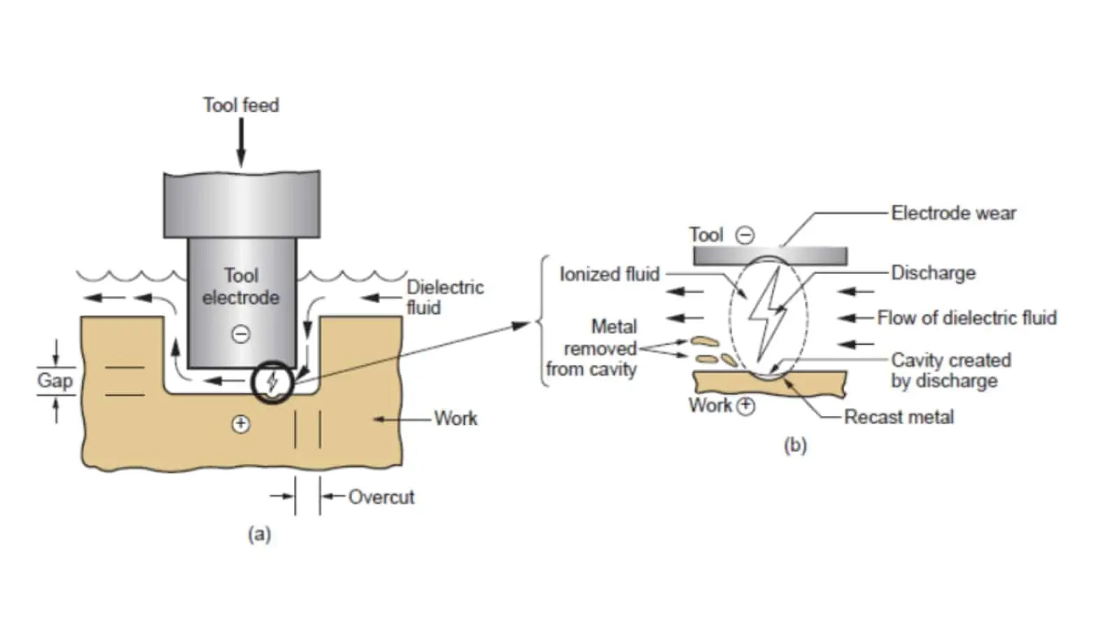
Sinker EDM can form detailed cavities, corners and difficult-access features using a planned electrode strategy. Electrode wear, spark allowance and downstream finishing requirements are reviewed before committing the machining sequence.

Precision Grinding
Precision grinding refines critical faces, diameters or datum features after machining and applicable heat-treatment steps. Grinding stock, sequence and inspection method are defined to manage surface condition and dimensional relationships.
Threads, Surface Treatments and Assembly Features for CNC Machined Clevises
Threaded Features
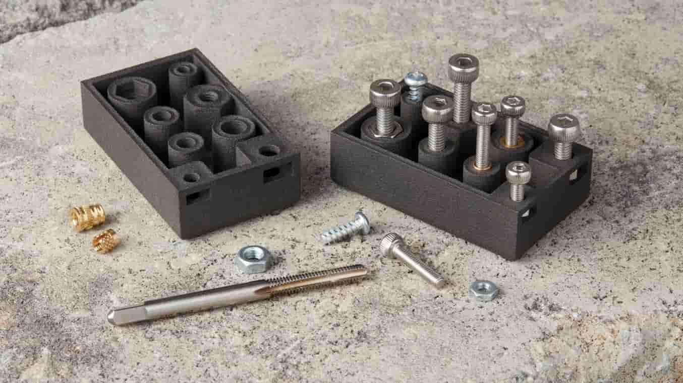
Internal or external threads can be reviewed with the clevis drawing, including thread standard, engagement length, datum relationship and gauging requirement. Early review helps confirm machining access and inspection planning.

Clevis Pins
Drawing-specified pins can be coordinated with the clevis fork and hole requirements, including fit, retention method, material and surface condition. Mating-part context helps identify functional dimensions before production.

Precision Bushings
Bushings support controlled interfaces where wear, movement or replaceability matters. Provide the bore, outside diameter, fit intent, material requirement and assembly sequence so machining and inspection can be planned appropriately.
Surface Treatments
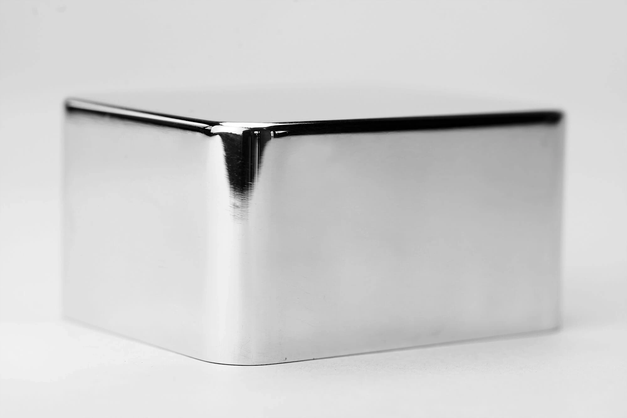
Coating, plating or other specified surface treatments should be evaluated with masking areas, dimensional priorities and post-treatment inspection needs. SUUXIANG reviews the requirement against the drawing and verified project scope.

Heat Treatment
Where heat treatment is required, identify material grade, hardness range, critical dimensions and finishing sequence. This allows grinding allowance, distortion risk and final inspection requirements to be considered before commitment.
Part Marking
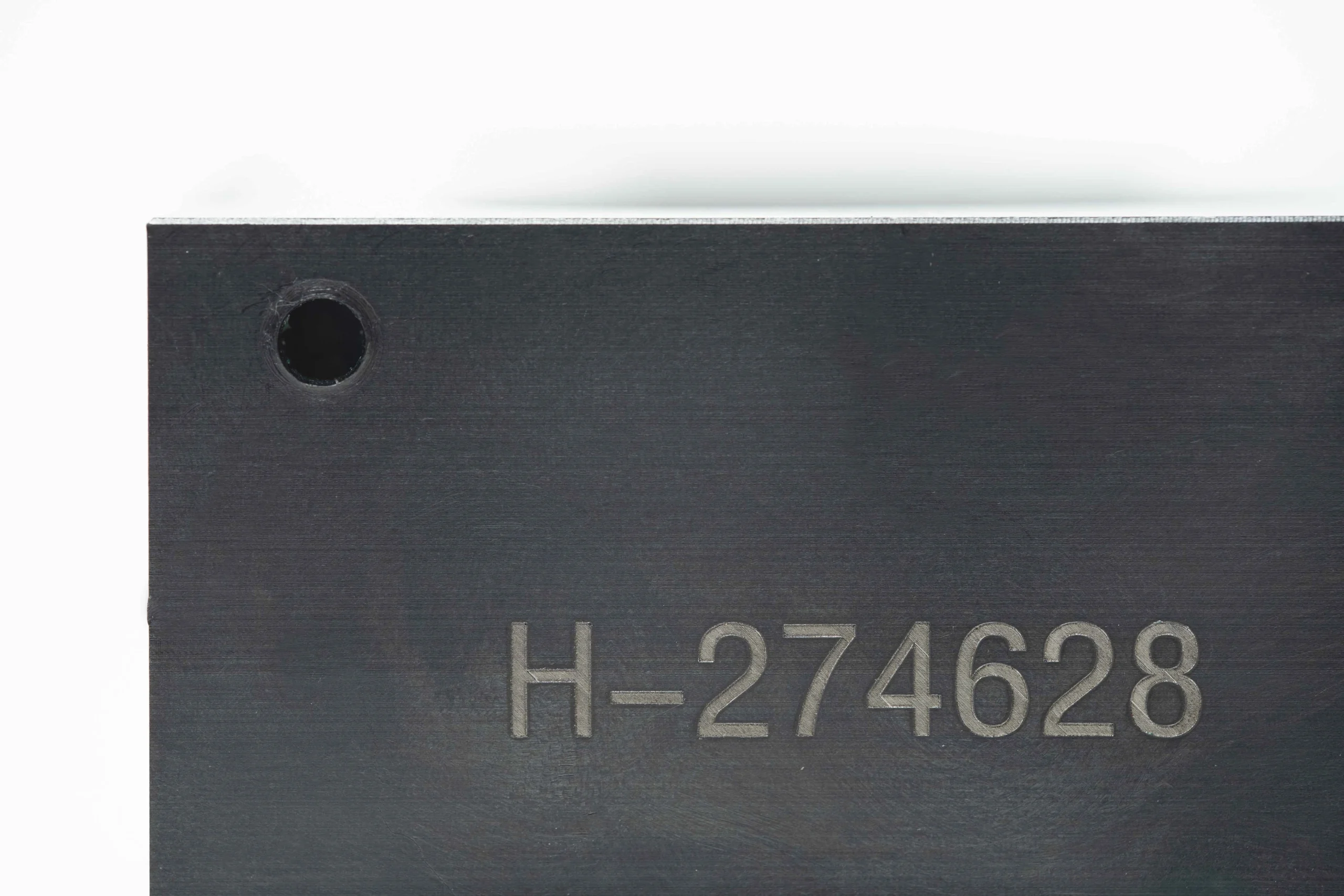
Part numbers, revision marks or traceability identifiers can be included when drawing-specified. Define marking location, method and legibility requirements to avoid interference with critical surfaces, mating interfaces or protective finishes.
About SUUXIANG CNC Machined Clevises
SUUXIANG is the public-facing brand of Dongguan SuuXiang Precision Mold Co., Ltd., established in 2010 in Chang’an Town, Dongguan, Guangdong, China. We help international engineering, sourcing and quality teams turn drawings into inspected custom CNC parts, precision mold components, connector tooling and die components.
For CNC machined clevises and other drawing-based parts, our planning connects CNC milling and turning, multi-axis machining, EDM, precision grinding, fitting and inspection as the project requires. Before quotation or production commitments, we review critical dimensions, datums, material requirements, machining access, surface priorities and inspection expectations.
Our difference is a disciplined, evidence-led workflow. We keep DFM findings, revision control, process decisions and delivery information visible, so buyers can evaluate manufacturability before production begins. Send a 2D drawing, 3D model where available, quantity, material, quality requirements and target date for a focused project review.

Engineering Controls for CNC Machined Clevises
Datum and DFM Review
Before quotation, SUUXIANG reviews CNC machined clevises against their mating function, datums, fork spacing, pin-hole relationship, thread callouts, tool access, and critical dimensions. This identifies tolerance-stack and machining-access risks while changes are still practical to discuss.
- Confirm functional datums and critical-to-quality dimensions
- Review fork-slot geometry, pin-hole position, and wall thickness
- Check thread, relief, chamfer, and deburring requirements
- Align the drawing revision with the quotation basis

Process Route Planning
Clevis geometry often combines turned features, milled forks, cross holes, and controlled bearing surfaces. SUUXIANG plans the appropriate sequence of CNC machining, EDM, grinding, and fitting based on the drawing, material condition, hardness requirements, feature access, and required inspection evidence.
- Select milling or turning around the part’s governing geometry
- Evaluate wire EDM or electrode strategy for inaccessible features
- Reserve grinding stock where finish or geometric control requires it
- Plan heat-treatment sequence to manage distortion risk
Inspection Built Into Planning
Inspection planning begins with the approved drawing, not only at final release. For CNC machined clevises, SUUXIANG aligns measurement methods to the specified datums, pin bores, fork opening, center distances, threads, surface requirements, and any order-specific reporting expectations.
- Define inspection points from drawing callouts and functional datums
- Match gauges and measurement methods to feature geometry
- Clarify first-piece, in-process, and final-report expectations
- Keep documentation aligned with the verified inspection plan
Revision-Controlled Coordination
A reliable clevis order depends on keeping technical decisions visible from review through delivery. SUUXIANG coordinates drawing revisions, material and process requirements, inspection expectations, and delivery information so the production route and final documentation correspond to the agreed order basis.
- Record the applicable drawing and revision before release
- Escalate manufacturability questions before production commitments
- Maintain traceable communication on approved requirement changes
- Coordinate delivery against the confirmed project information

CNC Machined Clevises: SUUXIANG vs. a General-Purpose Machine Shop
Compare the drawing-control practices that help teams align clevis features, process routes, inspection, and revisions before production.
← Swipe left or right to view →
CNC Machined Clevises: From Drawing Review to Shipment
A drawing-driven route that keeps critical dimensions, process decisions, inspection expectations and delivery requirements visible before production begins.
Review Drawings and Requirements
SUUXIANG reviews the 2D drawing, model, material, quantity, application, datums, critical dimensions, surface requirements, inspection needs and requested delivery date before quotation.
Plan Material and Process
The team confirms the practical machining route, stock condition, heat-treatment sequence, tool access, machining allowance, and whether EDM or grinding is relevant to specified features.
Machine Critical Features
CNC milling, turning or multi-axis machining establishes the clevis form, bores, slots, threads and locating features according to the approved drawing and revision.
Finish and Inspect Parts
Where required, EDM, grinding, fitting and deburring support feature completion. Inspection follows the agreed plan, with critical dimensions and documentation checked against order requirements.
Pack and Coordinate Delivery
Accepted parts are packed to protect finished surfaces and identified for traceability. SUUXIANG coordinates shipment details and communicates revision, inspection and delivery information with the customer.
How to Work With SUUXIANG on CNC Machined Clevises
Share the production inputs early so DFM, inspection planning, and delivery coordination can be aligned before machining begins.
Submit Your Drawing Package
Upload the 2D drawing and available 3D model, then specify material, quantity, application context, delivery target, and required inspection documentation.
Review DFM and Quotation
Confirm critical dimensions, datums, tolerances, surface requirements, tool access, heat-treatment sequence, and proposed machining route before quotation and production commitments.
Approve Samples When Needed
For applicable projects, review sample or first-article requirements against the agreed drawing revision, critical features, inspection method, and acceptance criteria.
Coordinate Production and Delivery
SUUXIANG coordinates machining, EDM, grinding, fitting, inspection, revision visibility, and delivery information according to the confirmed order and inspection plan.
Quality Documentation and Certification Evidence
The Complete Buyer’s Guide to CNC Machined Clevises
Customer feedback for CNC machined clevises is published only after written approval, with the drawing revision, inspection scope, delivery result, and measurable project outcome verified for accuracy.
SUUXIANG does not create anonymous customer quotations. A future testimonial will identify the applicable manufacturing scope and verified outcome, such as 1 drawing revision clarified before production.
Project feedback is retained until customer permission and supporting records are available. This keeps statements about CNC machined clevises, inspection documentation, and delivery coordination traceable to the order.
CNC Machined Clevises FAQ
Practical answers for drawing-based sourcing, from RFQ inputs and inspection planning to delivery coordination.
What information do you need to quote cnc machined clevises?
Is there a minimum order quantity for cnc machined clevises?
Can I order a sample before full production of cnc machined clevises?
What materials can be considered for a custom clevis?
How are tight tolerances on clevis slots and pin holes controlled?
Can cnc machined clevises include threads, surface treatment or assembly features?
What inspection documentation can be requested with a clevis order?
How should I plan lead time, shipping and payment for a custom order?
The Complete Buyer’s Guide to cnc machined clevises
Use this practical framework to specify cnc machined clevises, compare materials and processes, evaluate capable suppliers, control inspection requirements, and avoid costly design, quotation, and production-release mistakes.
1. What Are cnc machined clevises?
Two parallel ears separated by a slot define a clevis: the fork accepts a mating lug, while a transverse pin or pivot carries the connection. A clevis body is the forked part; the clevis pin is the separate cylindrical retention or pivot element; together with the mating member, they form a clevis joint.
Three common machining actions create drawing-specific cnc machined clevises: milling establishes outer profiles and fork faces, drilling produces the cross-hole, and slotting forms the internal opening. Turning may first create a cylindrical body, thread, shoulder, or a separate pin before secondary milling and drilling; production examples combine turning, milling, drilling, and slot machining (https://www.solutionsmfg.net/project-portfolio/agriculture/clevis-block).
One catalog clevis is appropriate only when its thread, fork width, pin-hole size, material, load case, and interface already match the design. A custom-machined component is warranted when the drawing controls datums, nonstandard geometry, fit with a mating part, surface condition, heat-treatment sequence, or inspection evidence; provide the 2D drawing, 3D model, pin specification, and critical dimensions for review.
2. Evolution of Clevis Manufacturing
Two production routes still shape clevis sourcing: forged or manually machined hardware for established forms, and drawing-controlled CNC production for application-specific geometry. The former can be economical when tooling and the geometry are already fixed; the latter keeps revisions, datums, and critical features tied to the released drawing.
3-axis milling established repeatable slot, hole, and thread relationships, while 4- and 5-axis setups can reduce re-clamping on clevises with angled or multi-face features. Purpose-built fixtures locate from defined datums, limiting setup-to-setup variation and making inspection results more comparable across lots.
1 digital model and controlled inspection plan now allow prototype quantities to expose tool-access, burr, and tolerance-stack risks before a production release. For cnc machined clevises, select the route by critical dimensions, volume, and revision frequency—not by the assumption that one legacy process will preserve lifecycle consistency.
3. Types of cnc machined clevises
Six common architectures cover most drawing-based cnc machined clevises. Select by force direction, pin retention, mating thread or bore, and the datum that controls fork spacing.
Threaded Rod-End Clevises
One threaded shank joins a fork to an adjustable rod. Axial load should pass through the thread shoulder and pin centerline; turning followed by milling suits this form.
Fork-End Clevises
Two parallel ears receive a mating lug and transverse pin. Ear thickness, inside gap, and hole position govern bearing and bending; CNC milling or a turned-and-milled blank is typical.
Clevis Blocks
One block combines a threaded bore, slot, and cross-hole. The slot creates the critical load path, so mill it from a stable datum after turning or in a multi-axis setup.
Pin-And-Slot Assemblies
Two mating pieces transfer motion through a pin in a controlled slot. Specify pin fit, slot width, travel, and retention; milling, drilling, and separate pin turning are common.
Compact Precision Clevises
Small clevises concentrate tolerance stack in fork gap and pin bore. Micro machining, Swiss turning, and precision milling may be evaluated when tool access and inspection demand it.
Application-Specific Variants
Application-specific variants add offsets, locating faces, seals, or anti-rotation features. Share mating-part geometry and load direction so SUUXIANG can review CNC, EDM, grinding, and inspection requirements.
4. Materials for cnc machined clevises
Material selection for cnc machined clevises starts with load path, pin contact, corrosion exposure, and temperature. Confirm the exact grade only after validating stress, mating materials, finish, and required material documentation.
| Material Family | Typical Priority | Operating Environment | Key Caution |
|---|---|---|---|
| Aluminum alloys | Low weight, machinability | Dry or protected service | Validate bore wear and coating |
| Carbon or alloy steels | Strength, wear | Loaded mechanisms | Specify corrosion protection |
| Stainless steels | Corrosion resistance | Wet or chemical exposure | Confirm machinability and galling risk |
| Brass | Machinability, corrosion | Moderate-load fittings | Validate strength and temperature |
| Engineering plastics | Low friction, insulation | Low-load, limited heat | Check creep and moisture effects |
Strength And Weight
Aluminum alloys reduce mass and machine efficiently, but pin-bore wear requires design attention.
Carbon and alloy steels favor higher strength and wear resistance, with protective finishing often considered.
Environment And Finish
Stainless steels suit wet or corrosive service, though machinability varies by grade and condition.
Brass machines readily and resists corrosion; engineering plastics suit low-load, nonabrasive, temperature-limited applications.
Traceability Before Release
Mill certificates should identify material grade, heat or lot, condition, and applicable specification.
Drawing notes should define heat treatment, coating, masking, and post-finish critical dimensions.
5. Custom Features and Surface Finishes
A 2D drawing should define every functional feature of cnc machined clevises, not merely overall shape. SUUXIANG reviews the mating pin, datum scheme, finish callout, and packaging need before production planning.
| Treatment | Functional Purpose | Dimension Control |
|---|---|---|
| Anodizing | Corrosion protection | Mask fits; inspect finished surfaces |
| Passivation | Stainless corrosion resistance | Protect threads and critical surfaces |
| Zinc or nickel plating | Corrosion or contact performance | Define thickness and post-plate fit |
| Black oxide or polishing | Appearance, handling, or surface condition | State oiling and measurement stage |
Feature Definition
A slot requires width, depth, end-radius, datum, and allowable burr condition; bore geometry needs size, location, and pin-fit intent. Threads, counterbores, reliefs, and edge radii should be dimensioned from functional datums.
A revision-controlled model can clarify tool access, while the drawing remains the dimensional authority. Identification marking needs location, method, legibility requirement, and any prohibited surface.
Finish As A Requirement
A finish specification must state its function: corrosion resistance, wear behavior, electrical contact, appearance, or heat-treatment response. Anodizing, passivation, zinc or nickel plating, black oxide, polishing, and heat treatment are selected against that requirement.
A coated bore or thread can lose clearance, so masking and post-finish dimensions require explicit agreement. Inspection planning should identify whether measurements apply before finish, after finish, or both.
Packaging For Assembly
A packaging instruction should specify part orientation, lot separation, protective media, label content, and pack quantity. Assembly-ready packs reduce mixed-revision and finish-damage risks during receiving.
6. Critical Quality Elements in Clevises
Clevis reliability is governed by the relationship between the fork, pin, and mating linkage—not by any isolated dimension. Convert each assembly requirement into a datum-based, measurable callout before release.
Datums and Fork Geometry
Datum A should be the primary mounting face or threaded axis; Datum B can establish the pin-hole centerline. Control fork parallelism and slot width relative to these datums so the linkage is not side-loaded.
A functional gauge using the specified mating pin can verify entry, clearance, and fork alignment more directly than separate measurements alone.
Holes, Threads, and Bearings
Pin-hole diameter, true position, and coaxiality determine pivot fit. Call out the mating pin diameter and required clearance, then specify the inspection method for each critical feature.
Thread class, effective engagement, bearing-face flatness, and surface finish should be tied to their functional interfaces rather than left as general notes.
Condition and Inspection Records
Edge breaks and complete burr removal protect assembly personnel and prevent false seating. Define permitted edge condition where a sharp transition or controlled radius affects strength or fit.
Material grade, heat-treatment condition, and required finish belong on the drawing or purchase specification. Request a first-article record that identifies datums, instruments, actual critical results, revision, and any functional-gauge result.
7. How to Choose a Clevis Manufacturer
A clevis supplier should be assessed against the released drawing, annual volume, risk level, and launch date. Capability claims matter less than evidence tied to those requirements.
Test The Drawing Review
Within 2 business days, request written clarification of datums, fork-slot access, pin-hole strategy, burr limits, and tolerance conflicts.
A useful DFM response identifies assumptions and alternatives; a generic quote does not.
Verify Process And Controls
For each critical feature, request a process plan linking turning, milling, EDM, grinding, deburring, and finishing to inspection points.
A first-article report should show actual values, measuring method, revision, material traceability, and disposition of nonconforming results.
Check Production Readiness
Before release, compare prototype and production routes for fixture strategy, material availability, finishing coordination, inspection capacity, and change control.
SUUXIANG can review these drawing-based requirements through its CNC, EDM, grinding, fitting, and inspection workflow; acceptance remains project-specific.
8. Common cnc machined clevises Sourcing Mistakes
Before purchase-order release, one early DFM review should include design, quality, manufacturing, and procurement. That review converts drawing assumptions into documented process ownership and functional acceptance criteria.
Pin Fit And Datums
An unspecified pin fit can produce a clevis that assembles with unacceptable play or will not accept its mating pin. Ask: What pin diameter, fit condition, load direction, and clearance or interference are required?
Two incomplete tolerances or ambiguous datums can make individually conforming features misalign at assembly. Ask: Which datum scheme controls fork faces, bore position, slot width, and perpendicularity?
Finish, Material, And Edges
A plated bore changes the finished interface, while material chosen only by unit price may miss strength, corrosion, wear, or heat-treatment needs. Ask: Are finished dimensions specified after coating, and what material condition is functionally required?
One omitted deburring criterion leaves variable edge breaks, burrs, and potential mating-part damage. Ask: Which edges require a defined break, burr-free hole exit, or protected cosmetic surface?
Process Ownership And Functional Approval
One split process chain can lose accountability between machining, heat treatment, coating, and inspection. Ask: Who owns the routed process, revision status, final inspection plan, and nonconformance response?
A first article measured only against isolated dimensions can still fail in the mating assembly. Ask: Will approval include the specified pin, articulation check, clearance check, and applicable load-path review?
9. From Drawing to Production Release
A controlled release begins with one revision-controlled 2D drawing and matching CAD model. For cnc machined clevises, the RFQ should also state application load, mating pin or fork details, annual volume, and target delivery date.
Submit A Complete Technical Package
Three inputs prevent avoidable assumptions: drawing, model, and a CTQ list. Identify datums, toleranced pin bores, slot width, thread callouts, material, heat treatment, finish, and required certificates.
One application note should describe load direction, movement, corrosion exposure, and mating-part interfaces. State prototype, tooling, or low-volume production quantity separately from forecast demand.
Close DFM And Quote Assumptions
Two reviews should precede a purchase order: DFM feedback and quotation alignment. Confirm machining access, workholding, burr-break expectations, process route, inspection method, exclusions, and any assumptions about supplied material or post-processing.
One approved quotation must reference the controlled revision. Resolve conflicts between CAD, drawing notes, and email instructions before programming begins.
Release With Evidence And Controls
First-article approval should compare the agreed CTQ dimensions and finish requirements against the drawing. Lock the inspection plan, report format, sample disposition, packaging quantity, protection method, and labeling before routine shipments.
One change-control rule should require written approval for revision, material, process, finish, or packaging changes. Define replenishment triggers, forecast updates, and communication owners for subsequent releases.
10. cnc machined clevises Pricing and Lead Time
Three quotation variables usually dominate a clevis: material and blank form, setup count, and total cutting or EDM cycle time. Tight positional tolerances, difficult tool access, special cutters, deburring, heat treatment, plating, inspection reports, and protective packaging add cost or calendar risk.
1–10-piece prototypes carry the largest setup share per part; these are quotation variables, not SUUXIANG prices. Lead time also depends on material availability, approved drawings, outsourced secondary processes, inspection scope, and revision stability.
Two practical changes can reduce total landed cost: combine compatible requirements into one controlled drawing package, and simplify nonfunctional radii, pockets, or tolerance zones. Preserve datum-critical pin bores and mating faces, but ask during drawing review whether a standard blank, fewer orientations, or sampled reporting can meet the application need.
| Quantity tier | Unit-cost direction | Setup-cost impact | Typical lead-time factors |
|---|---|---|---|
| 1–10 | Highest | High per part | First article, material, complex routing |
| 11–100 | Declining | Spread across lot | Fixture, inspection, finishing |
| 101+ | Lower if repeatable | Lower per part | Capacity, batch processing, release schedule |
Upload Your CNC Machined Clevis Drawing for Review
Include material, quantity, critical dimensions, delivery target, and inspection requirements for a disciplined DFM and quotation review.