
CNC Parts for Vibration Test Adapters, Reviewed Before Machining
SUUXIANG reviews cnc parts for vibration test adapters for DFM, critical dimensions, datum strategy, and inspection planning before production.
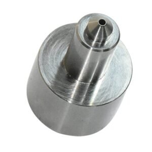
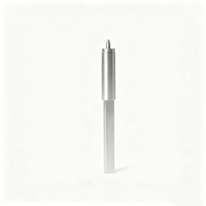
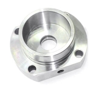
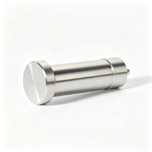
Representative Components for Vibration-Test Adapter Development





Representative Components and Drawing-Based Quotation





CNC Parts for Vibration Test Adapters: Engineering Advantages
A drawing-driven workflow that keeps critical interfaces, process decisions, inspection expectations, and revisions visible before production commitments.
Drawing-Led DFM Review
Review critical dimensions, datums, mounting interfaces, tool access, and tolerance stack risks before quotation and process planning.
Integrated Process Planning
Plan CNC machining, wire EDM, sinker EDM, grinding, fitting, and finishing around geometry, material, and functional requirements.
Critical-Dimension Focus
Identify dimensions that affect alignment, fastening, mating components, and test setup so inspection priorities reflect the application.
Inspection Plan Alignment
Define appropriate measurement methods, reporting needs, and acceptance expectations from the drawing before parts enter final inspection.
Revision-Control Discipline
Keep drawing revisions, agreed clarifications, and manufacturing updates traceable to reduce ambiguity across engineering, quality, and procurement teams.
Clear Project Communication
Coordinate material, heat treatment, surface requirements, quantity, delivery targets, and application context through a structured technical discussion.
Component Families for Vibration-Test Tooling
Configure precision parts and tooling families around fixture loads, datums, mating interfaces, inspection requirements, and revision-controlled production.

CNC Machining Services
Precision CNC machining services convert vibration-test fixture drawings into custom structural, locating, and interface parts. DFM review clarifies critical dimensions, material requirements, machining access, and inspection priorities before a process route is committed.
Upload a Drawing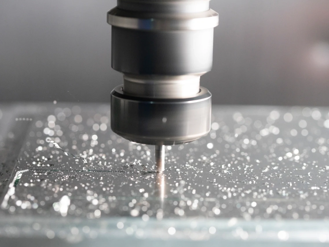
CNC Milling
Custom CNC milling services support plates, brackets, fixture bodies, nests, and complex mounting interfaces. Tool access, clamping strategy, datum locations, and tolerance relationships should be reviewed where vibration loads or repeated assembly affect performance.
Upload a Drawing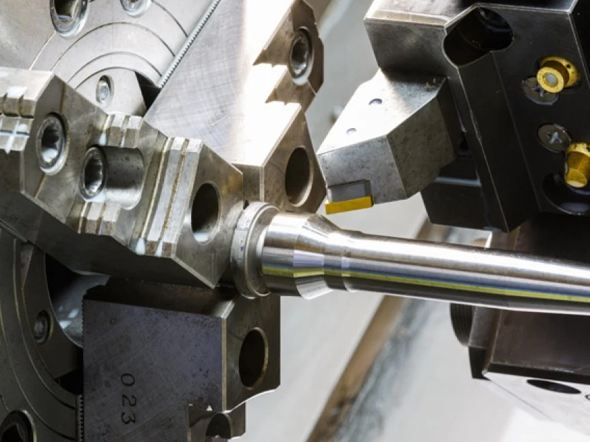
CNC Turning
Precision CNC turning services produce cylindrical adapters, spacers, bushings, threaded interfaces, and locating features. Concentricity, runout, mating threads, bearing fits, and measurement methods should be defined from the drawing and application context.
Upload a Drawing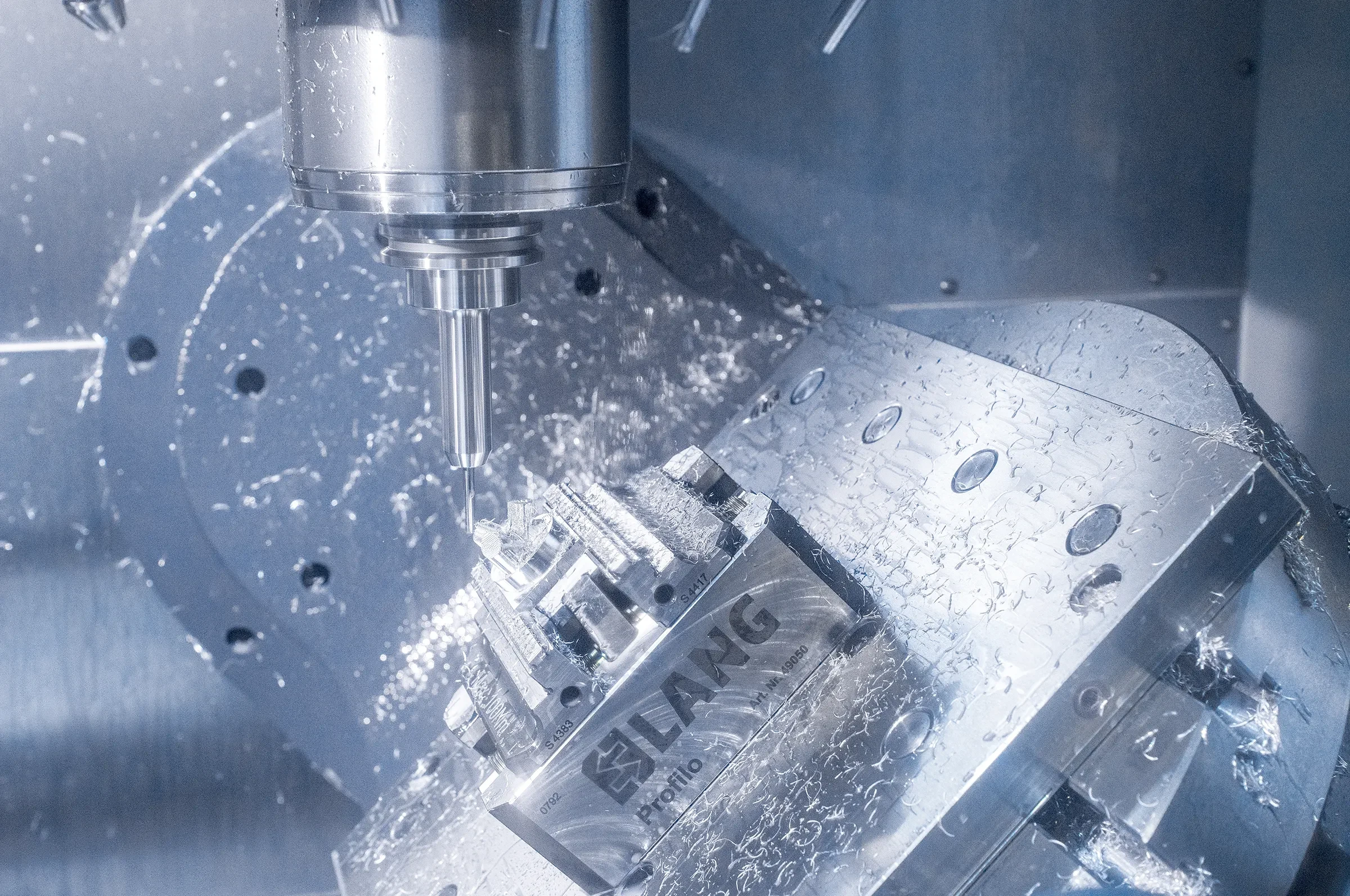
5-Axis Machining
5-axis CNC machining helps consolidate angled features, compound surfaces, and multi-face interfaces into fewer setups. For vibration-test tooling, review tool reach, fixture rigidity, datum transfer, and critical feature accessibility before selecting the route.
Upload a Drawing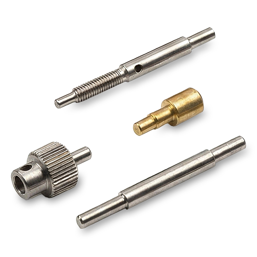
Swiss & Micro Machining
Swiss machining and micro machining support small-diameter pins, shafts, sleeves, contacts, and miniature locating elements. Drawings should identify functional diameters, surface requirements, cut-off considerations, and inspection expectations for features sensitive to handling or assembly.
Upload a Drawing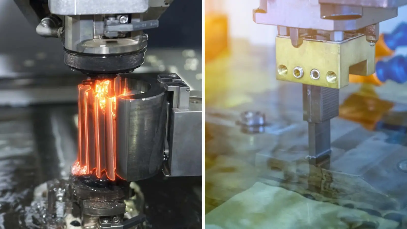
Wire & Sinker EDM
Wire EDM and sinker EDM services address narrow slots, sharp internal profiles, hardened features, deep cavities, and difficult-to-machine geometry. Electrode strategy, wire path, corner conditions, recast-layer considerations, and downstream finishing requirements require early review.
Upload a Drawing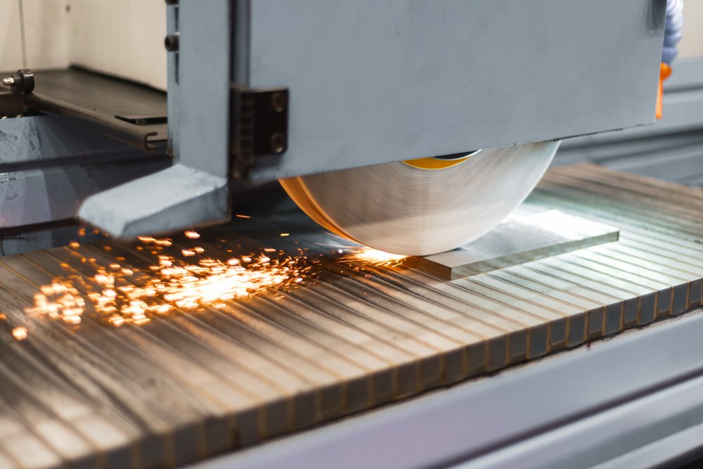
Precision Grinding
Precision surface and profile grinding supports flatness, parallelism, profile control, and controlled fit on fixture and tooling components. Specify datum surfaces, grinding stock, heat-treatment sequence, surface requirements, and the inspection method for critical interfaces.
Upload a Drawing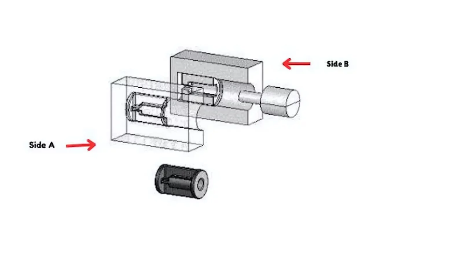
Mold Core & Cavity Inserts
Precision mold core and cavity inserts are configurable around part geometry, material, heat treatment, cooling, shutoff conditions, and finishing needs. SUUXIANG reviews machining, EDM, grinding, fitting, and inspection requirements against the approved drawing.
Upload a Drawing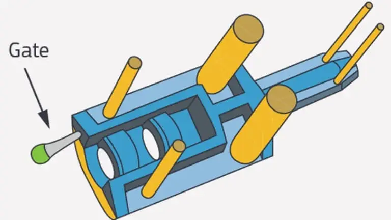
Ejector & Ejection Components
Ejector pins, sleeves, and ejection components require attention to fit, guidance, wear surfaces, heat treatment, and mating-hole conditions. Define operating motion, dimensional priorities, material requirements, and any polishing or inspection criteria before production.
Upload a Drawing
Core Pins, Guide & Locating Components
Core pins, guide pins, and locating components establish repeatable relationships between tooling elements. Functional diameters, engagement lengths, clearance or interference requirements, datum references, hardness, and mating-component information help determine the appropriate manufacturing sequence.
Upload a Drawing
Slides, Lifters, Gates & Mold Accessories
Mold slides, lifters, gates, and accessories are configured around travel, shutoff geometry, wear, fit, and assembly interfaces. Drawings should make motion relationships, critical contact areas, material treatment, and fitting expectations visible before machining begins.
Upload a Drawing
Connector Mold Components
Precision connector mold components support detailed cavity, core, terminal, and alignment features used in connector tooling. Pin geometry, pitch relationships, EDM requirements, grinding strategy, surface condition, and inspection planning should follow the approved design revision.
Upload a Drawing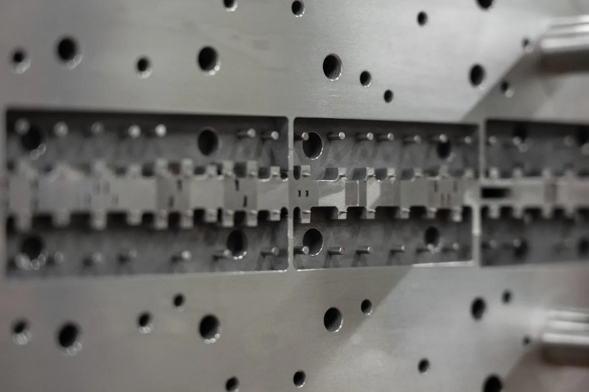
Stamping Die Components
Precision stamping die components include punches, dies, guide elements, plates, and custom forming features. Material condition, heat-treatment sequence, cutting-edge geometry, clearance relationships, grinding allowance, and inspection requirements should be established before release.
Upload a Drawing
Injection, MIM, CIM & Overmolding Tooling
Injection, MIM, CIM, and overmolding tooling components are evaluated within verified production scope. Provide molding material, geometry, shrinkage assumptions, insert or mating details, critical dimensions, surface expectations, and trial-stage requirements for an informed review.
Upload a Drawing
Machining Materials
CNC machining materials should be selected for load, wear, corrosion exposure, stability, heat treatment, and mating conditions. State the required grade or approved equivalent, material condition, certification needs, and any restrictions before quotation.
Upload a Drawing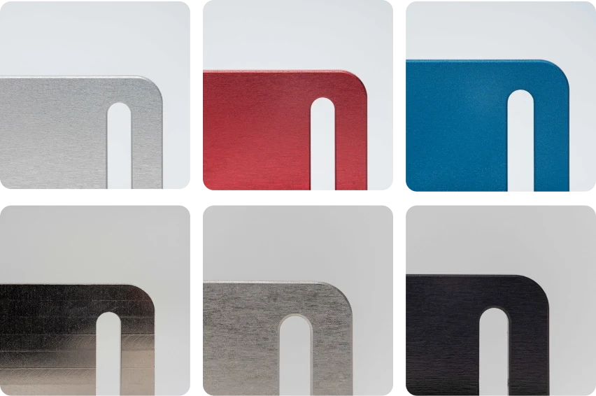
Surface Finishes & Heat Treatment
Surface finishing and heat treatment affect fit, wear, corrosion resistance, dimensions, and subsequent machining or grinding. Identify required treatment, finish targets, masking areas, sequence constraints, and any verification records needed with the RFQ.
Upload a Drawing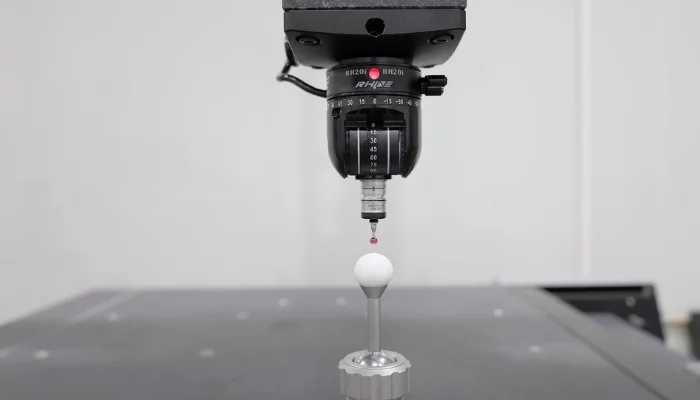
Quality, Metrology & Documentation
Precision inspection, metrology, and quality documentation are planned around the drawing’s critical dimensions and agreed inspection method. Identify datums, reporting requirements, sampling expectations, revision level, material records, and any customer-specific traceability needs.
Upload a Drawing
Prototyping & Low-Volume Production
Rapid prototyping and low-volume manufacturing support drawing-driven validation parts, fixture iterations, replacement components, and controlled pilot quantities. Share quantity, target date, revision status, material, critical features, and inspection needs to align the manufacturing plan.
Upload a DrawingMaterials for CNC Parts for Vibration Test Adapters
Aluminum Alloys
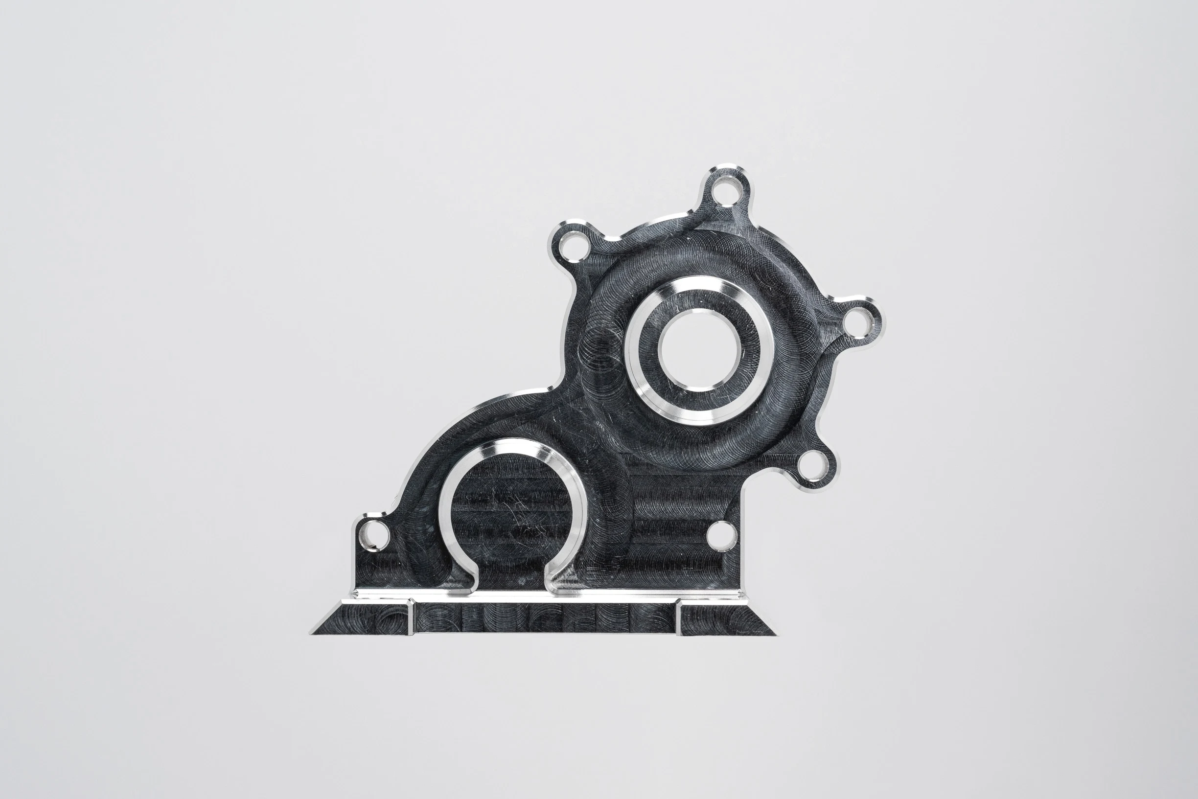
Often selected for lighter adapter plates and brackets where stiffness-to-mass balance matters. They machine efficiently, but alloy temper, section thickness, thread loading, and surface-treatment requirements should be confirmed from the drawing and test conditions.
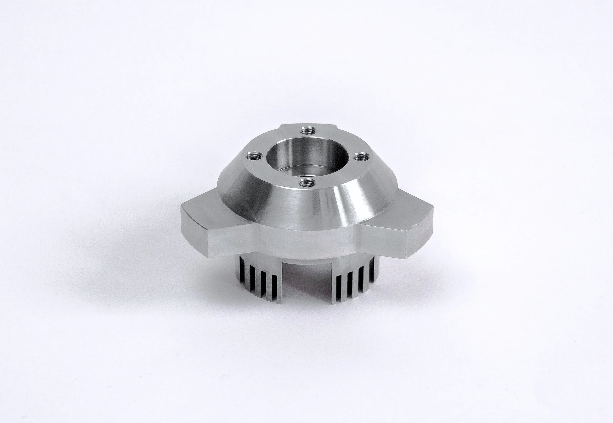
Stainless Steel
Considered for adapter components needing corrosion resistance, durable threaded features, or robust interfaces. Machinability varies by grade, so the material callout, heat condition, critical bores, and surface-finish expectations require review before process planning.
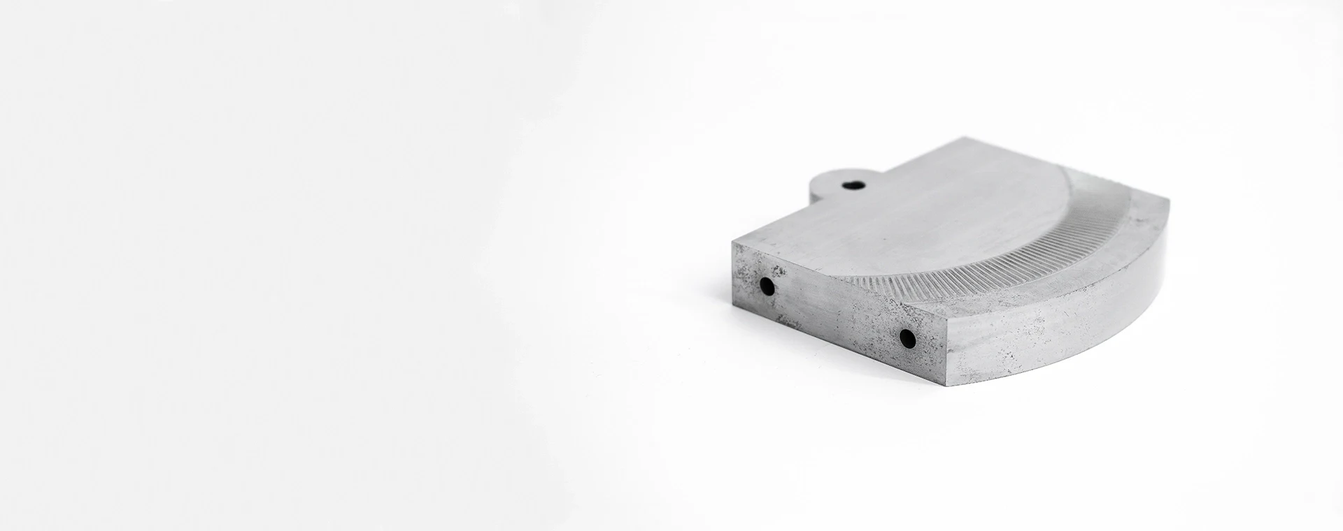
Tool Steel
Suitable for wear-prone locating elements, precision interfaces, and components requiring heat-treatment coordination. Machining, EDM, grinding allowance, hardness sequence, and inspection points must be aligned with the drawing so critical geometry remains verifiable.
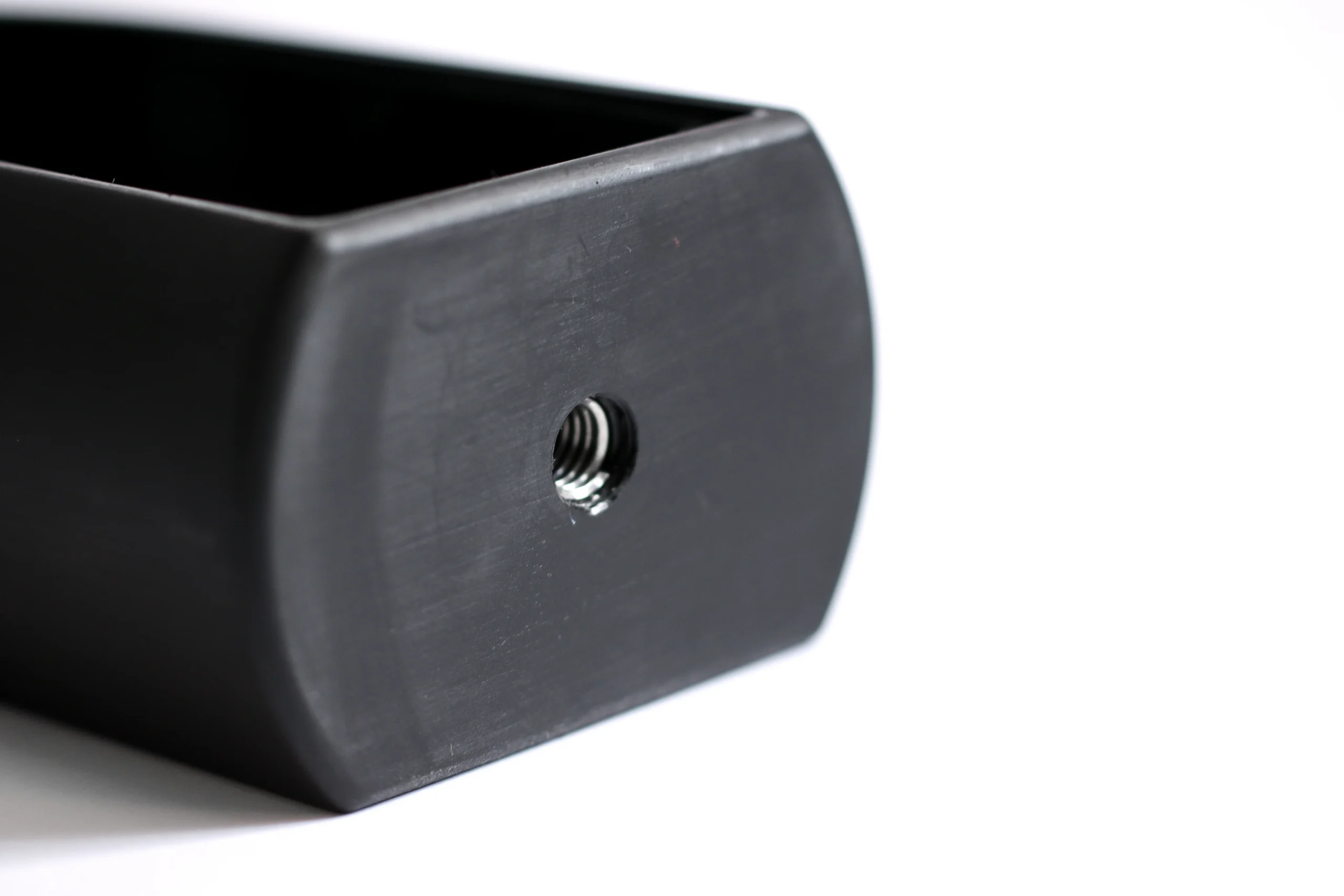
Engineering Plastics
Used where electrical isolation, lower mass, or non-marring contact surfaces influence the adapter design. Material grade, dimensional stability, fastening method, environmental exposure, and tolerance priorities should be evaluated against the intended test setup.
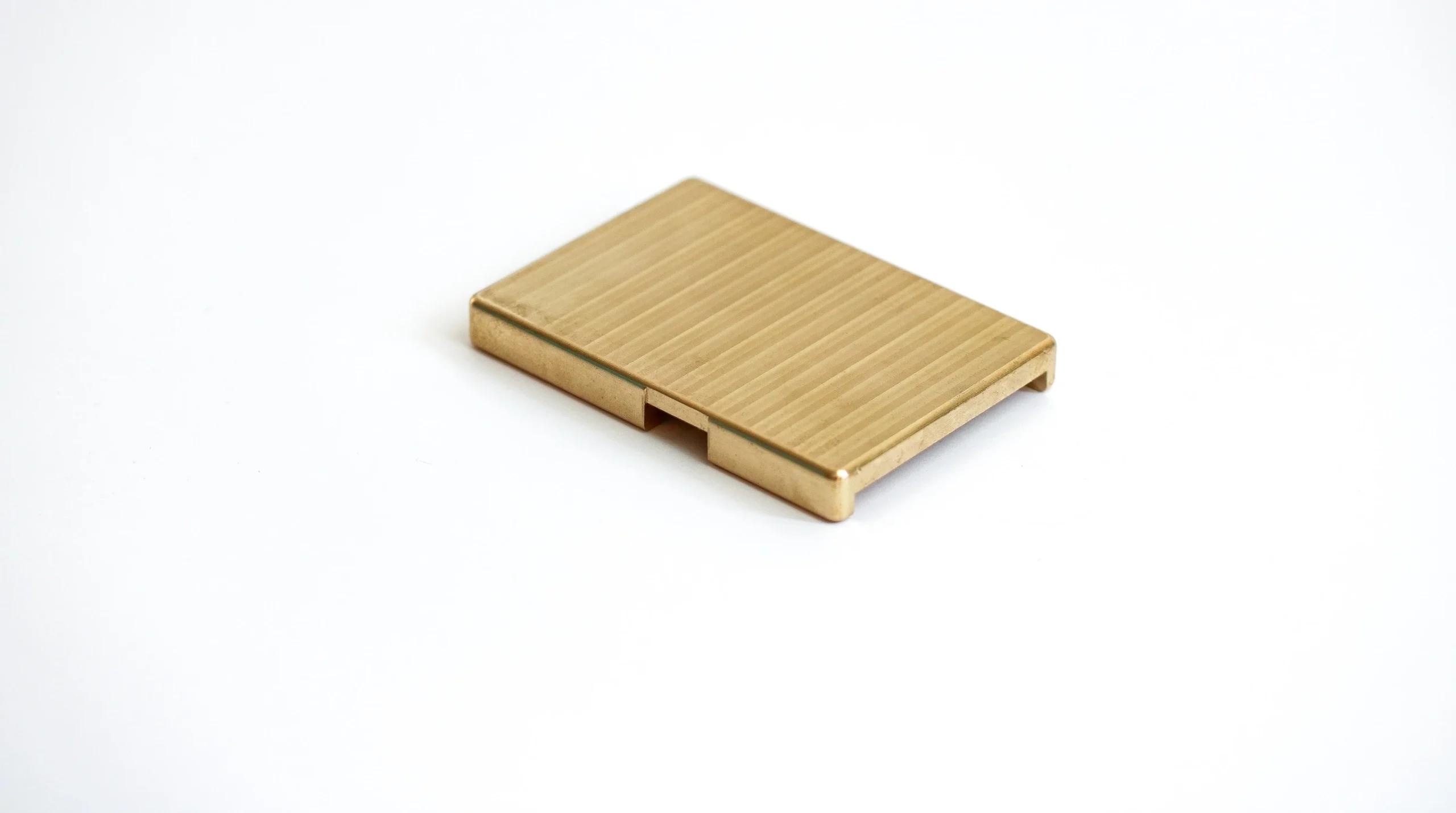
Brass Alloys
A practical option for conductive interfaces, fittings, and smaller machined details requiring clean cutting characteristics. Alloy selection, contact function, thread geometry, plating needs, and dimensional inspection requirements should be defined in the RFQ.
CNC Parts for Vibration Test Adapters: Precision Process Routes
CNC Milling
Milling forms adapter plates, pockets, mounting faces, slots and hole patterns from the approved drawing. Fixture strategy and cutting access are reviewed to protect datum relationships and leave suitable stock where later finishing is required.
CNC Turning
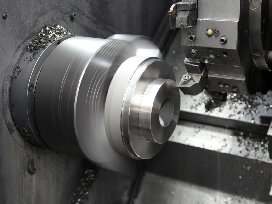
Turning supports rotational features such as bushings, spacers, shafts and threaded interfaces used in vibration-test assemblies. The route is selected when concentricity, seating geometry and repeatable cylindrical features must relate clearly to drawing datums.
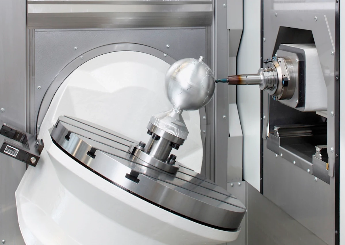

EDM Machining
Wire EDM and sinker EDM address profiles, internal corners and hardened or constrained features where conventional cutter access is limited. Electrode strategy, wire path, finish requirements and subsequent inspection points are agreed from the drawing.

Precision Grinding
Grinding is considered for controlled flatness, parallelism, surface condition and final-size features after the appropriate machining or heat-treatment sequence. Grinding allowance and datum transfer should be defined early to avoid compromising critical interfaces.
Fitting And Inspection
Fitting and inspection verify assembly-related interfaces, critical dimensions and drawing-defined acceptance criteria. The inspection method, reporting need, revision status and any mating-component context are clarified before release, supporting traceable communication for CNC parts for vibration test adapters.
CNC Parts for Vibration Test Adapters: Hardware and Finishing Options
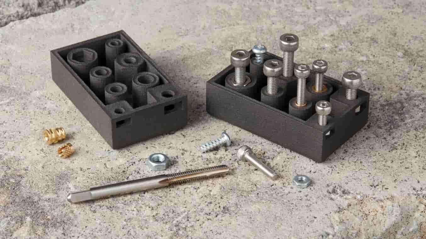
Threaded Inserts
Threaded inserts can provide durable attachment points in adapter bodies where repeated assembly is expected. Provide insert type, thread size, installation method, parent material and any pullout or torque requirements for drawing review.

Specified Fasteners
Fasteners may be coordinated when the drawing identifies size, grade, head style, finish and mating condition. Clarifying supplied-versus-installed hardware, tightening access and any captive-feature requirement helps prevent interface assumptions during production.

Locating Elements
Dowel-pin holes, locating pins, bushings and datum pads help establish repeatable positioning between the adapter, test article and fixture. Define functional datums, fit requirements, assembly sequence and inspection method before the machining route is confirmed.
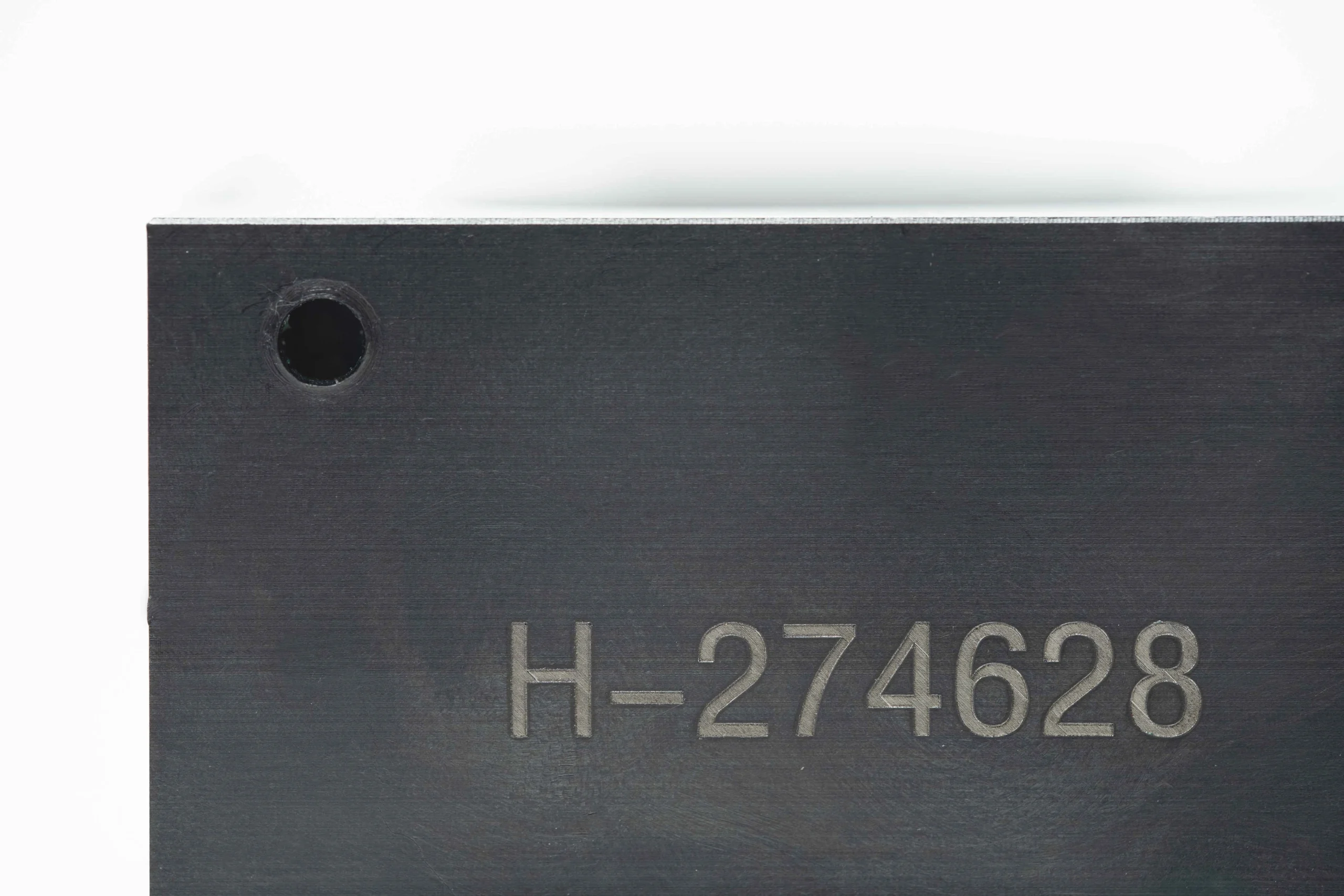
Part Identification
Laser-marked identifiers, revision marks or controlled label locations can support traceability during fixture assembly and test operations. Supply the required text, placement, contrast expectation and marking restrictions so the feature is evaluated against material and finish.
Controlled Finishing
Deburring, edge breaks, protective finishes and specified surface conditions should be tied to functional faces and handling needs. Identify masked zones, contact surfaces, coating thickness concerns and cosmetic limits for an appropriate machining and inspection plan.
About CNC Parts for Vibration Test Adapters
Established in 2010, Dongguan SuuXiang Precision Mold Co., Ltd. operates from the 2nd Floor of Sanhe Industrial Park in Chang’an Town, Dongguan, Guangdong, China. SUUXIANG is its sole public-facing brand, founded and legally represented by XiaoCheng Huang, supporting international engineering and sourcing teams with drawing-driven custom machined parts, precision mold components, connector tooling, and stamping-die components.
For cnc parts for vibration test adapters, SUUXIANG reviews critical dimensions, datum strategy, material and heat-treatment requirements, machining access, EDM or grinding needs, and inspection expectations before production commitments. CNC milling and turning, multi-axis work, EDM, precision grinding, fitting and inspection are planned around the verified part requirement.
Our difference is disciplined coordination from revision-controlled drawing review through inspection documentation. SUUXIANG helps buyers identify manufacturability risks, clarify quality evidence and align delivery requirements early, so custom adapter components and related tooling can proceed with a defined process route and traceable communication.

CNC Parts for Vibration Test Adapters: Critical Capability Detail
Critical-Dimension Review
Before quotation, SUUXIANG reviews the drawing’s datums, mounting interfaces, hole locations, mating surfaces, and tolerance stack. This clarifies which requirements are function-critical and identifies access or setup risks before CNC parts for vibration test adapters enter production planning.
- Confirm datums and inspection references
- Separate critical features from general dimensions
- Review mounting patterns and mating interfaces
- Flag tolerance-stack and tool-access risks

EDM and Grinding Strategy
Complex profiles, hardened features, narrow slots, and precision surfaces may require more than milling alone. SUUXIANG evaluates wire EDM, sinker EDM, and precision grinding as part of the route, including machining allowance, electrode access, wire path, and heat-treatment sequence.
- Assess EDM suitability for intricate geometry
- Plan grinding stock on critical surfaces
- Coordinate sequence around heat treatment
- Review electrode and wire-path clearance
Integrated Process Planning
Adapter components are planned from the supplied drawing and application context, not treated as generic catalog parts. CNC machining, EDM, grinding, fitting, and inspection are coordinated around material requirements, quantity, surface priorities, and revision status to support a controlled manufacturing route.
- Match process route to drawing requirements
- Consider material and surface requirements
- Maintain visible revision control
- Coordinate fitting where assembly interfaces demand it

Inspection Matched to Risk
Inspection planning should follow the drawing’s critical-to-quality features and agreed reporting needs. SUUXIANG aligns measurement methods, datum references, and final documentation with the order requirements, helping sourcing and quality teams receive traceable evidence appropriate to the specified adapter part.
- Define inspection priorities before production
- Reference agreed datums during measurement
- Specify report and documentation needs in RFQ
- Keep final records aligned with the order
Why Choose SUUXIANG for CNC Parts for Vibration Test Adapters
Compare drawing review, process planning, inspection focus, and revision communication before committing production.
← Swipe left or right to view →
Production Workflow for CNC Parts for Vibration Test Adapters
A controlled path from drawing review to documented inspection and delivery coordination.
Review Drawings and Requirements
We review drawings, models, material, quantity, application context, critical dimensions, datums, surface requirements, inspection needs, and target delivery before confirming a feasible production route.
Plan DFM and Process
Our team identifies tool access, setup strategy, tolerance stack risks, machining allowance, heat-treatment sequence, and where EDM or grinding may be required for critical features.
Machine Critical Adapter Features
CNC milling, turning, multi-axis machining, or micro-machining are selected according to the approved part geometry, material condition, feature access, and dimensional priorities.
Apply EDM and Grinding
Where specified features require it, wire EDM, sinker EDM, and precision grinding are planned around electrode strategy, wire path, hardened condition, and remaining finishing stock.
Inspect Against Approved Requirements
Inspection follows the agreed plan, checking critical dimensions, datum relationships, surfaces, and required documentation so reported results correspond to the released drawing revision.
Pack and Coordinate Delivery
Accepted parts are packed for the component’s handling needs, while revision status, documentation, quantities, and delivery coordination remain visible through final project communication.
How to Source CNC Parts for Vibration Test Adapters
Use a controlled, drawing-driven workflow to align manufacturability, inspection expectations, revisions, and delivery requirements before production proceeds.
Submit Your Design Package
Provide 2D drawings, 3D models when available, material, quantity, application context, target date, and critical dimensional, surface, heat-treatment, and reporting requirements.
Review Manufacturability Together
Align on datums, tolerance stack, machining access, fastening interfaces, EDM or grinding needs, inspection methods, and revision status before SUUXIANG prepares a quotation.
Approve Samples or First Articles
When applicable, review prototype, sample, or first-article requirements against the agreed drawing and inspection plan before releasing the controlled production order.
Proceed With Controlled Production
SUUXIANG coordinates the agreed CNC machining, EDM, grinding, fitting, inspection, revision communication, and delivery documentation according to the confirmed order requirements.
CNC Parts for Vibration Test Adapters: Documentation Review
CNC Parts for Vibration Test Adapters: Verified Project Results
Customer testimonial reserved for an approved project record. Published outcomes will identify the drawing revision, inspected dimensions, quantity, delivery context, and authorization scope before release.
Customer case-study entry reserved for documented results. Any published performance figure will be tied to the applicable adapter component, inspection record, project quantity, and customer publication authorization.
Customer feedback entry reserved for an authorized sourcing project. SUUXIANG will publish only traceable outcomes supported by the customer-approved scope, including relevant revision-control and quality-documentation context.
FAQ: CNC Parts for Vibration Test Adapters
Practical answers for drawing-based adapter-component sourcing, from review inputs through documentation and revision control.
What should I send for a quote on cnc parts for vibration test adapters?
Can I order low-volume cnc parts for vibration test adapters or only production quantities?
How do you evaluate a drawing for cnc parts for vibration test adapters?
Can SUUXIANG provide samples before a larger order?
What determines lead time for adapter components?
How should material and heat-treatment requirements be specified?
What inspection reports can be requested with CNC adapter parts?
How are drawing revisions, shipping, payment, and IP handled?
Complete Buyer’s Guide to cnc parts for vibration test adapters
Use this decision framework to specify vibration-test adapter components, compare material and manufacturing criteria, qualify capable suppliers, control cost, and avoid drawing, resonance, inspection, and launch mistakes.
1. What Are cnc parts for vibration test adapters?
Three load paths define cnc parts for vibration test adapters: the shaker or base fixture, the adapter assembly, and the device under test. The assembly commonly includes machined plates, brackets, housings, locating features, threaded interfaces, and specified fasteners that transfer excitation while holding the intended mounting relationship.
Two questions govern the drawing review: what forces and moments must each interface carry, and which datums must return to the same position after installation? Hole patterns, locating diameters, bearing faces, thread engagement, clearance envelopes, and center-of-gravity references should be defined against the test setup—not merely modeled as convenient geometry.
One adapter assembly is separate from both the test article and the instrumentation. The test article is the product being qualified; accelerometers, cables, and data-acquisition hardware measure the response, while the machined adapter provides the repeatable mechanical connection between them and the shaker or fixture.
2. How Vibration Adapter Design Evolved
One-piece fixture plates can solve basic shaker-table mounting. As payloads, interface constraints, and qualification plans grow, adapters become application-specific structures with controlled load paths, mounting patterns, and access for multiple orientations.
Modal behavior, stiffness, center of gravity, and the intended test range must be reviewed for the assembled system rather than inferred from part geometry alone. The RFQ should link the controlled drawing revision to the 3D model, load case, orientation, material condition, critical interfaces, and inspection plan so the proposed machining route is evaluated against the test purpose.
3. Types of cnc parts for vibration test adapters
CNC parts for vibration test adapters are best classified by how they transmit shaker force, restrain the DUT, and establish repeatable interfaces. The drawing must define the full assembled load path, not isolated part geometry.
| Type | Use And Load Path | Mounting Pattern | Drawing Details |
|---|---|---|---|
| Base plate | Shaker-to-fixture force path | Grid or custom bolt pattern | Hole coordinates, flatness, threads |
| DUT bracket | Fixture-to-product force path | Product-specific points | Envelope, CG, access, datums |
| Multi-axis frame | Reorients DUT load path | Bolted joints | Orientations, ribs, fasteners |
| Spacers and standoffs | Sets stack height | Through-bolt or threaded | Length, faces, engagement |
| Locating features | Repeats position | Pins, keys, shoulders | Fits, position, datum |
| Guarded modular assembly | Protects or swaps interfaces | Covers and replaceable blocks | Assembly view, clearances, revision |
Interface And DUT Parts
Base plates carry force from the shaker table through a defined bolt pattern; flatness, counterbores, thread callouts, and table coordinates are quotation essentials.
DUT brackets transfer that force into product mounting points. Supply the DUT envelope, mass center, fastener access, datum scheme, and allowable clearance.
Frames And Spacing Sets
Multi-axis frames reposition a DUT for different test directions, so rib geometry, joint fasteners, and each orientation require definition.
Spacer and standoff sets establish stack height and clamp load. State lengths, mating faces, thread engagement, quantity, and whether parts must remain matched.
Locating And Guarded Assemblies
Dowel bores, shoulders, keys, and locating pins control repeatable position; identify primary datums, fit class, positional tolerance, and installation direction.
Guarded or modular assemblies add covers, replaceable interface blocks, or cable clearances. Provide assembly drawings, exploded views, torque limits, and revision-controlled part numbers.
4. Materials for cnc parts for vibration test adapters
Material for cnc parts for vibration test adapters follows the validated load case, frequency range, mounting geometry, environment, and electrical requirements. No default grade can substitute for modal, fatigue, corrosion, and interface review.
| Material | Best Fit | Key Watchpoint |
|---|---|---|
| Aluminum | Low mass structures | Thread wear |
| Stainless steel | Corrosive environments | Higher mass |
| Alloy steel | Loaded interfaces | Corrosion treatment |
| Titanium | Weight-critical duty | Machining cost |
| Engineering plastics | Electrical isolation | Creep and stiffness |
Structural Metals
6061 aluminum machines readily and reduces moving mass; 7075 increases strength where corrosion control is acceptable.
304 or 316 stainless suits wet or corrosive exposure, while alloy steel favors durable threads and highly loaded interfaces.
Fatigue And Threads
Repeated loading makes notch geometry, preload, and surface condition as important as nominal strength.
Steel inserts or hardened thread zones may be preferable where aluminum threads see frequent assembly cycles.
Titanium And Plastics
Titanium is justified when strength-to-weight and corrosion resistance outweigh slower machining and higher cost.
PEEK, acetal, or similar engineering plastics fit nonstructural isolation, wear, or contamination-sensitive features after temperature and creep review.
5. Custom Features and Finishes
Two drawing controls govern useful customization: datum-based location and a stated inspection method. For cnc parts for vibration test adapters, features should serve mounting repeatability, cable safety, or part traceability before appearance.
| Feature Or Finish | Primary Value | Drawing Risk |
|---|---|---|
| Hole grid | Repeatable mounting | Datum error |
| Dowel bores | Setup repeatability | Fit stack-up |
| Engraving | Traceability | Added inspection |
| Anodizing | Corrosion protection | Fit buildup |
| Plating | Functional surface | Masking lead time |
Mounting Feature Strategy
One hole grid can speed repeated shaker-table setups when pitch, datum origin, thread callout, and counterbore depth are defined. Dowel-pin bores improve positional repeatability, but their relationship to mating holes adds stack-up and usually needs measured location reporting.
Clearances And Identification
Two cable-clearance details matter: edge radius and clearance relative to connector travel. Pockets reduce mass or create access, while engraved identifiers and protective marking support configuration control; each added depth, edge condition, or marking location expands inspection and programming work.
Specify Finish By Function
Three finish questions should appear on the drawing: corrosion exposure, electrical-contact requirement, and cosmetic expectation. Anodizing, passivation, and plating require material-compatible specifications, masked areas where needed, and allowance for coating thickness on critical fits.
6. Quality Elements in Adapter Construction
Adapter accuracy is a test-validity control, not a cosmetic requirement. Resonance, joint slip, axis misalignment, or unnecessary fixture mass can alter the input reaching the device under test.
Mating Geometry
Flatness and perpendicularity should be specified from functional datums, with position tolerances controlling the shaker, adapter, and product interfaces.
Hole-to-hole accuracy preserves the intended bolt pattern; damaged edges or burrs can hold faces apart and create local looseness.
- Define primary, secondary, and tertiary datums
- Inspect mating faces after deburring
- Verify hole position against the drawing
Fasteners And Threads
Thread class, engagement length, seating-face condition, and tightening method should be controlled in the assembly record. A loose or poorly seated fastener can introduce relative motion, fretting, and nonrepresentative response.
- Specify fastener grade and torque method
- Protect threads during machining and handling
- Record locking features when required
Mass And Inspection Evidence
Mass and center-of-gravity values should be documented for the assembled adapter and test article. The vibration-bracket example at https://www.youtube.com/watch?v=1OfudKQQy78 highlights keeping modal behavior outside the test range and managing center of gravity to avoid shaker overload.
Dimensional inspection should report critical datums, flatness, perpendicularity, position, hole spacing, and threads; compare results to the released revision before test launch.
7. Choosing a Manufacturer for cnc parts for vibration test adapters
Custom test adapters and CNC prototype or small-series parts are established service categories (https://moteco.de/en/portfolio). For cnc parts for vibration test adapters, qualify the supplier against evidence for the exact drawing, not a broad capability list.
| Evaluation Area | Request | Part-Specific Evidence |
|---|---|---|
| Drawing review | DFM response | Datum and access notes |
| Inspection planning | FAI plan | Critical-feature method |
| Material control | Traceability need | Certificate match |
| Delivery continuity | Packaging plan | Revision-linked records |
Review The Drawing
Before quotation, require a review of datums, critical interfaces, tool access, setup count, and DFM risks. Ask for written feedback identifying assumptions, tolerance conflicts, and proposed process changes.
Verify Quality Evidence
For each part number, align material certificates when required, inspection points, reporting format, and first-article approval before production. SUUXIANG should confirm the applicable CNC, EDM, grinding, and multi-axis route from current project evidence.
Assess Delivery Control
For prototype-to-low-volume continuity, review revision control, named communication ownership, packaging protection, and shipment records. Require that drawing revisions, inspection results, and delivery status remain traceable through the approved order.
8. Common Sourcing Mistakes to Avoid
Before PO release, resolve interface, load-path, and inspection assumptions in the controlled drawing package. These errors typically become rework, delayed test setup, or invalid test correlation after hardware is machined.
Define Datums And Interfaces
Two interface drawings are required: one for the shaker and one for the DUT. Dimensions without datum references can produce a part that measures correctly yet misaligns the test assembly; identify mounting faces, locating features, orientation, and allowable interface variation before release.
Specify Fasteners And Holes
Three hole attributes must be distinguished: clearance, threaded, and precision-locating. Omitting fastener size, engagement, torque, washer use, and counterbore details risks joint slip, stripped threads, or clamp-load distortion; call them out with the mating hardware.
Review Stiffness Before Tolerance
One modal and load-path review should precede tolerance assignment. Over-tight tolerances raise cost without improving dynamic behavior, while price-only material selection can sacrifice stiffness, mass, corrosion resistance, or thread durability; set tolerances by functional datum and validate the intended test spectrum.
Plan Inspection Up Front
One inspection plan must be approved before machining begins. Requesting reports after production may leave critical features inaccessible or unmeasured; define CTQ dimensions, datum setup, measurement method, sampling, revision, and required records in the PO.
9. From Drawing Review to Test Launch
Two controlled inputs should start the launch: the test envelope and the interface definition. For cnc parts for vibration test adapters, freeze mounting pattern, load paths, frequency range, orientation, and mating hardware before machining.
Release The Technical Package
Engineering submits the current 3D CAD model, controlled 2D drawing, revision identifier, assembly context, and test constraints. It marks critical-to-function datums, interfaces, thread callouts, contact surfaces, and allowable mass or clearance limits.
Close DFM And Quality Risks
Quality and the manufacturer review tool access, fixture strategy, machining sequence, material condition, finish, and inspection method. Procurement confirms the approved quotation scope, required records, delivery need, and change-control route before release.
Validate Before Repeat Production
First-article or prototype parts should be checked against the agreed drawing revision and inspection plan, then trial-fitted to the shaker and mating assembly. Program management records fit results, deviations, corrective actions, and formal approval before repeat production.
10. Pricing cnc parts for vibration test adapters
1 prototype typically carries the highest unit cost because programming, fixturing, material preparation, and first-piece inspection are spread across one part. For cnc parts for vibration test adapters, cost rises with larger stock, additional setups, 4- or 5-axis access, tight datum-controlled features, and added grinding or EDM.
10–50 pieces can distribute setup cost, while repeat orders can reduce unit cost when the drawing, revision, material, and inspection plan remain stable. Lead time is driven by stock availability, machine routing, heat treatment or finishing, purchased hardware, inspection scope, and any expedited scheduling request.
2 practical savings actions are to specify critical tolerances only where function requires them and combine compatible features into accessible machining directions. Keep standard hardware and finish requirements clear, and provide the 2D drawing, model, mating context, quantity, and reporting needs for a comparable RFQ.
| Order tier | Relative unit-cost driver | Lead-time driver |
|---|---|---|
| Prototype, 1–2 | Highest: setup and inspection amortization | Programming, fixture planning, material sourcing |
| Low volume, 10–50 | Lower: setups shared across parts | Machine capacity, finishing, hardware |
| Repeat order, 50+ | Lowest when revision and route stay stable | Scheduled capacity and inspection release |
Submit Your CNC Parts for Vibration Test Adapters Drawing
Upload your 2D drawing and 3D model, with material, quantity, quality priorities, target date, and inspection requirements for a disciplined review.