
CNC Machined Heat Sinks, Reviewed Before Production
Send your drawing for DFM, critical-dimension, process, and inspection review of custom CNC machined heat sinks.
Representative Precision Manufacturing Work





Related Drawing-Based Components and Quotation




Why Choose SUUXIANG for CNC Machined Heat Sinks
Engineering decisions stay visible from DFM review through inspection, revision control, and delivery coordination.
DFM Before Commitment
We review fin geometry, tool access, datums, mounting interfaces, and machining risks before quotation or production commitments.
Integrated Process Planning
CNC machining, EDM, grinding, fitting, and inspection are planned around the drawing’s functional features and realistic process sequence.
Critical Dimensions First
Your critical dimensions, flatness priorities, and surface requirements guide datum strategy, machining allowance, and inspection planning.
Inspection Matched to Drawings
Inspection methods and requested reporting are aligned with the order, verified dimensions, and agreed quality expectations.
Revision-Controlled Communication
Drawing changes, manufacturing questions, inspection expectations, and delivery information remain visible throughout the project workflow.
Heat Sinks and Related Machined Part Families
Drawing-driven process routes for heat-sink components, tooling-related parts, and supporting precision work—configured to your material, geometry, inspection, and delivery requirements.

CNC Machining Services
Precision CNC machining services for custom machined parts, including heat sinks, mounting features, housings, manifolds, and related components. Drawing review focuses on thermal interfaces, fin geometry, datum strategy, tool access, material requirements, and inspection priorities before a process route is confirmed.
Upload a Drawing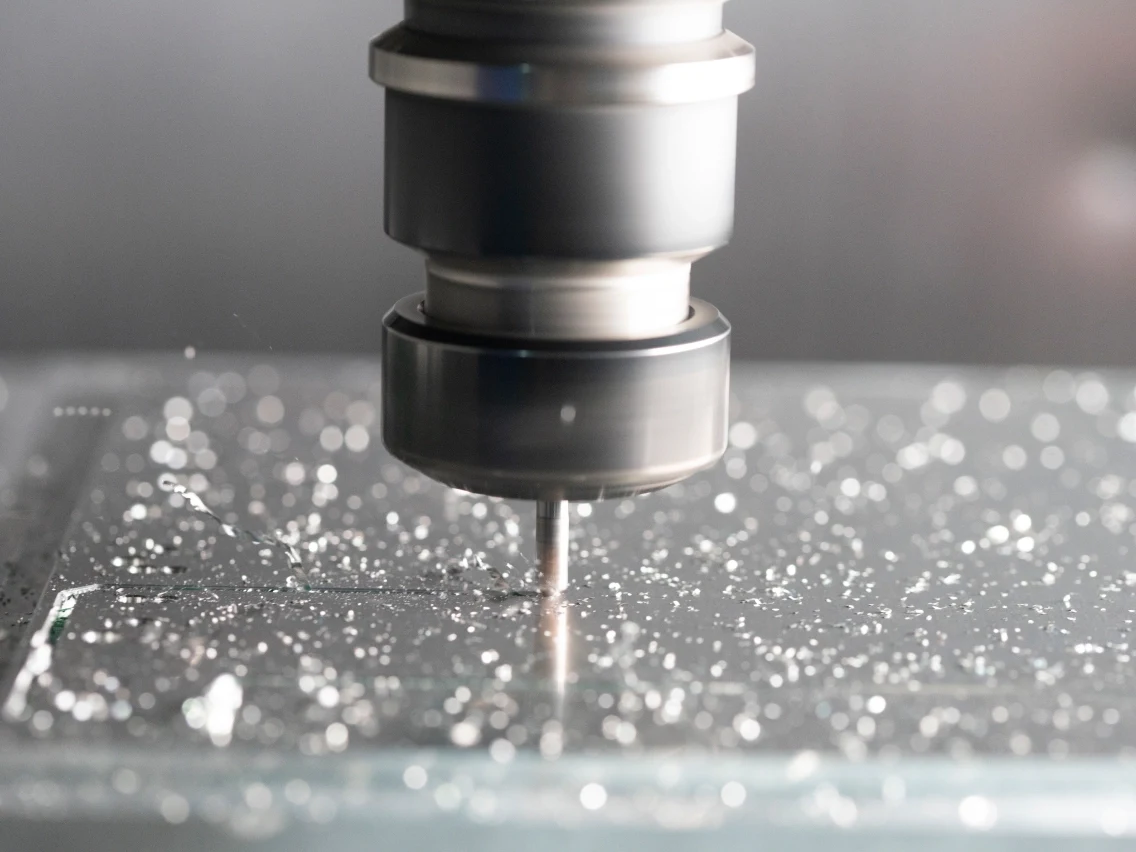
CNC Milling
Custom CNC milling services support heat-sink bases, finned forms, mounting patterns, pockets, channels, and complex machined interfaces. Review should establish cutter access, wall and fin stability, flatness requirements, burr control, and the dimensions that require planned inspection.
Upload a Drawing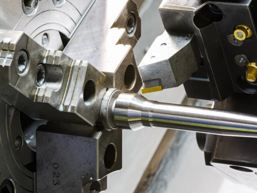
CNC Turning
Precision CNC turning services produce rotational heat-management and assembly parts, including collars, bushings, threaded features, spacers, and cylindrical housings. Specify concentricity, runout, thread requirements, material condition, surface priorities, and mating-component datums with the RFQ.
Upload a Drawing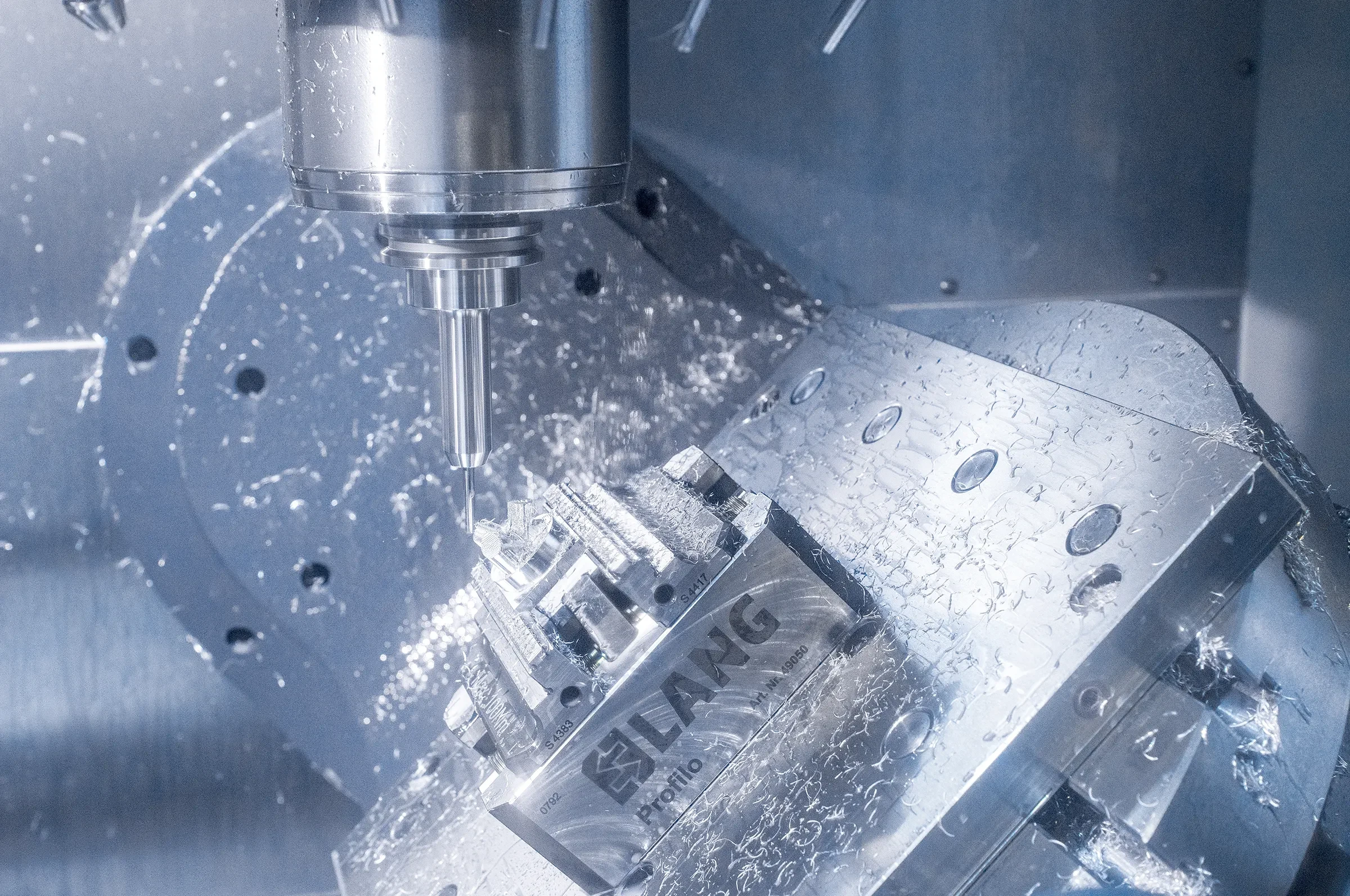
5-Axis Machining
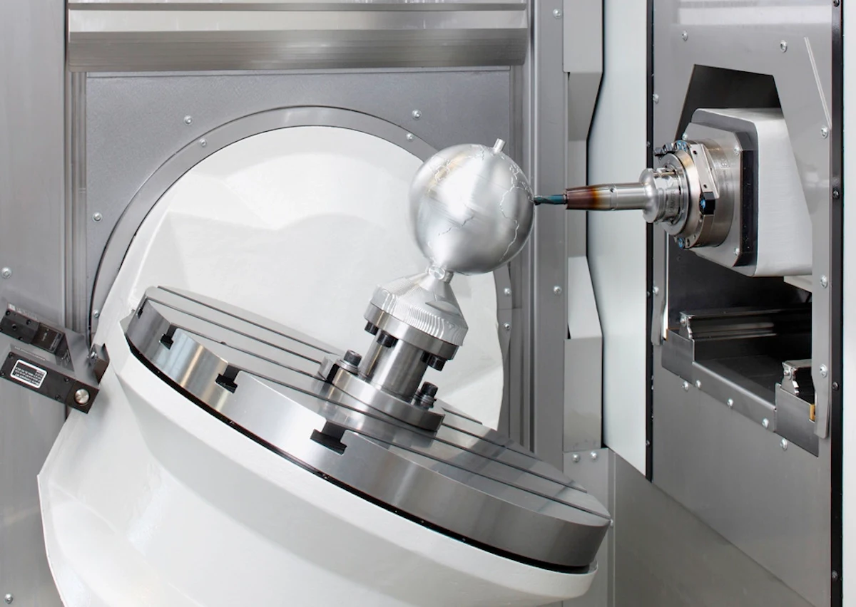
5-axis CNC machining supports complex heat-sink geometries and related components where multiple faces, angled features, or difficult tool approaches affect accuracy. Process planning evaluates fixture strategy, reachable surfaces, tool length, critical dimensions, and whether simultaneous machining is justified.
Upload a Drawing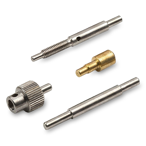
Swiss & Micro Machining
Swiss machining and micro machining support small, slender, or intricate components used with compact thermal assemblies, connector tooling, and precision mechanisms. Drawings should identify critical diameters, length-to-diameter concerns, threads, cross holes, material, and inspection methods for fine features.
Upload a Drawing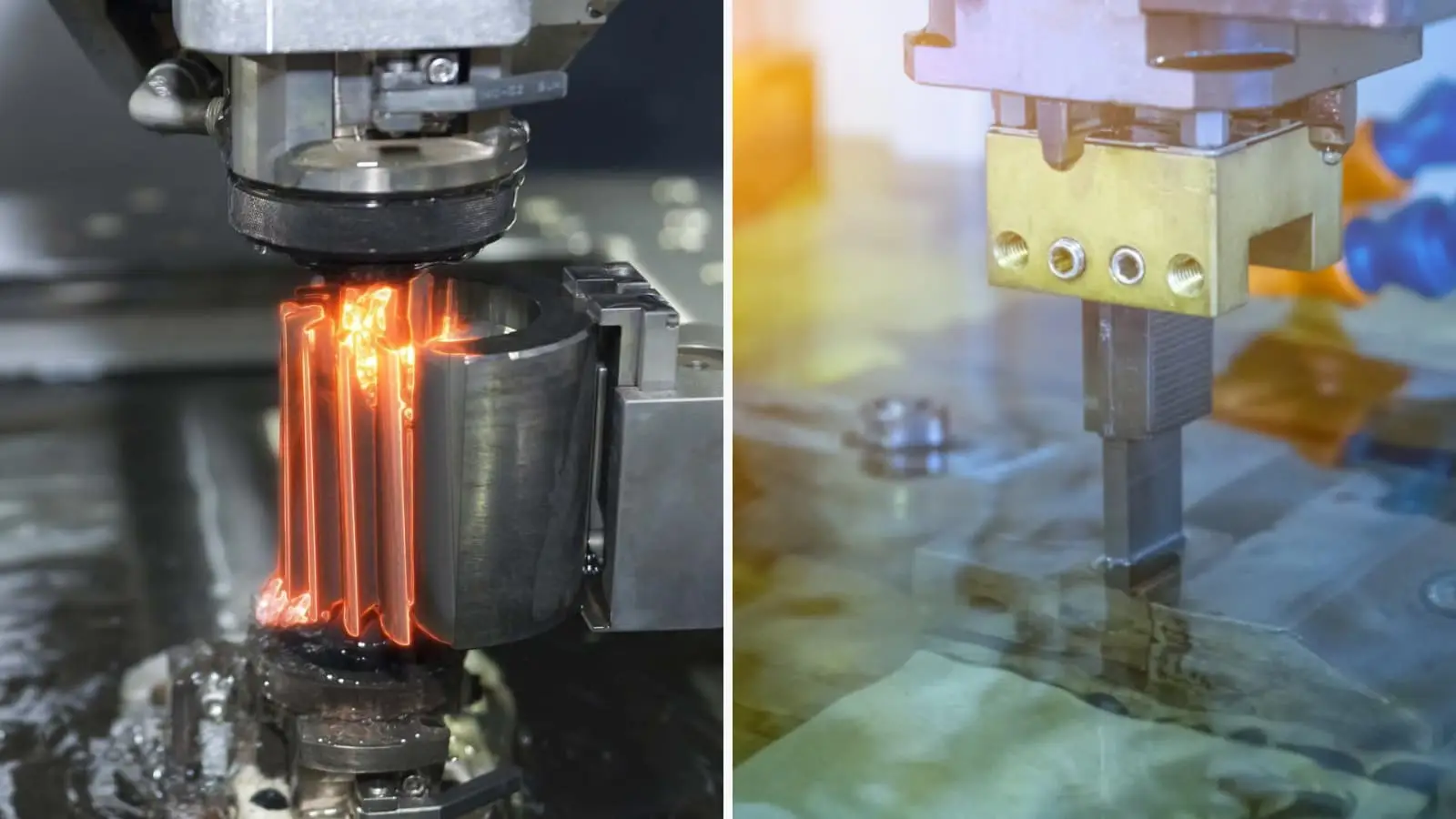
Wire & Sinker EDM
Wire EDM and sinker EDM services address hardened tooling features, narrow slots, sharp internal corners, precision cavities, and profiles beyond practical cutter access. Electrode strategy, wire path, recast-layer considerations, finishing allowance, and subsequent inspection should be agreed before production.
Upload a Drawing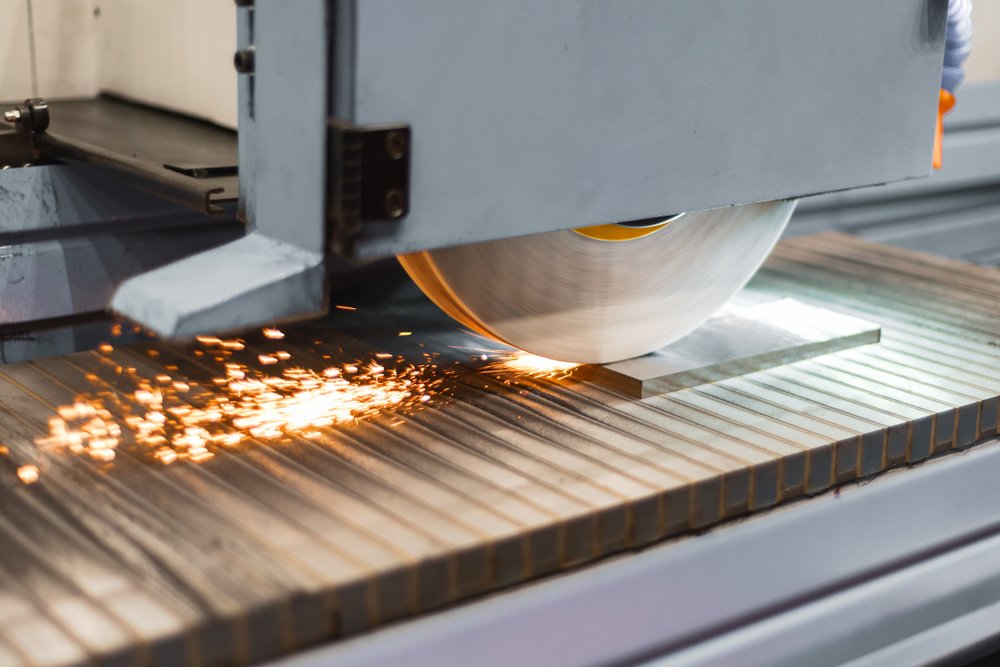
Precision Grinding
Precision surface and profile grinding supports controlled flatness, parallelism, thickness, profiles, and finishing dimensions on heat-sink interfaces and tooling components. Grinding stock, heat-treatment sequence, datum references, surface requirements, and inspection points guide the route.
Upload a Drawing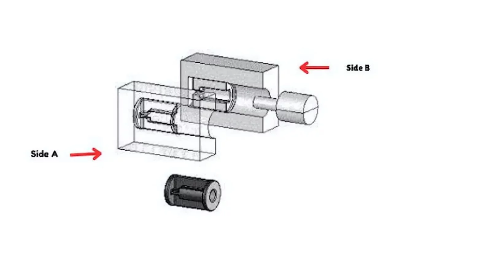
Mold Core & Cavity Inserts
Precision mold core inserts and mold cavity inserts are configurable components for tooling projects associated with molded thermal-management parts and enclosures. The drawing review addresses steel selection, cavity geometry, cooling considerations, EDM access, heat treatment, fitting relationships, and critical dimensions.
Upload a Drawing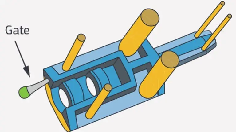
Ejector & Ejection Components
Ejector pins, sleeves, and ejection components are produced to drawing-defined dimensions and fit requirements for tooling projects. Specify diameters, lengths, head styles, hardness requirements, clearance relationships, surface condition, and the mating core or plate context.
Upload a Drawing
Core Pins, Guide & Locating Components
Core pins, guide pins, and locating components establish repeatable alignment and feature formation in molds and tooling. SUUXIANG reviews fit classes, datum relationships, wear surfaces, material and heat-treatment requirements, grinding needs, and the dimensions affecting assembly performance.
Upload a Drawing
Slides, Lifters, Gates & Mold Accessories
Mold slides, lifters, gates, and accessories are configured from approved drawings rather than stocked as assumed standard parts. Process planning considers travel and clearance interfaces, hardened surfaces, EDM features, fitting requirements, lubrication provisions, and revision-controlled assembly dimensions.
Upload a Drawing
Connector Mold Components
Precision connector mold components support tooling used for connector housings, terminals, and fine-pitch molded features. Reviews emphasize small-feature manufacturability, pin and cavity alignment, EDM strategy, wear areas, material condition, dimensional stack-up, and inspection evidence.
Upload a Drawing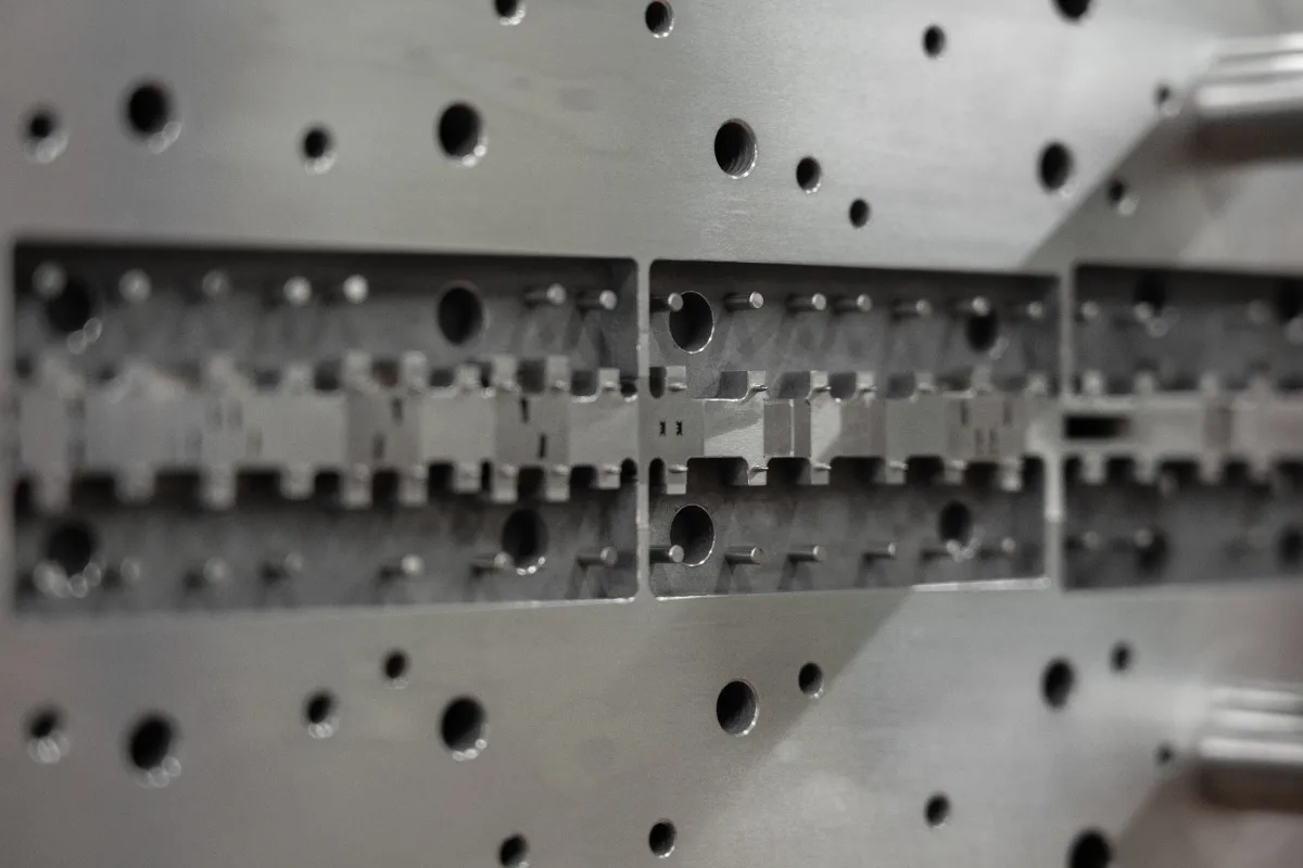
Stamping Die Components
Precision stamping die components include drawing-driven punches, dies, guide elements, inserts, and wear parts for forming and cutting tools. A practical review considers strip-contact geometry, clearance, material and heat treatment, grinding sequence, EDM requirements, and replacement-fit dimensions.
Upload a Drawing
Injection Mold Components, MIM, CIM & Overmolding Tooling
Injection, MIM, CIM, and overmolding tooling components are evaluated within verified production scope. Provide part geometry, material behavior, gate or flow considerations, critical interfaces, tooling steel requirements, molding application context, and inspection expectations so the process route can be assessed.
Upload a Drawing
Machining Materials
CNC machining materials are selected against thermal performance, strength, corrosion exposure, machinability, joining requirements, and application constraints. State the required material specification, temper or condition, approved substitute policy, traceability expectations, and any heat-treatment sequence before quotation.
Upload a Drawing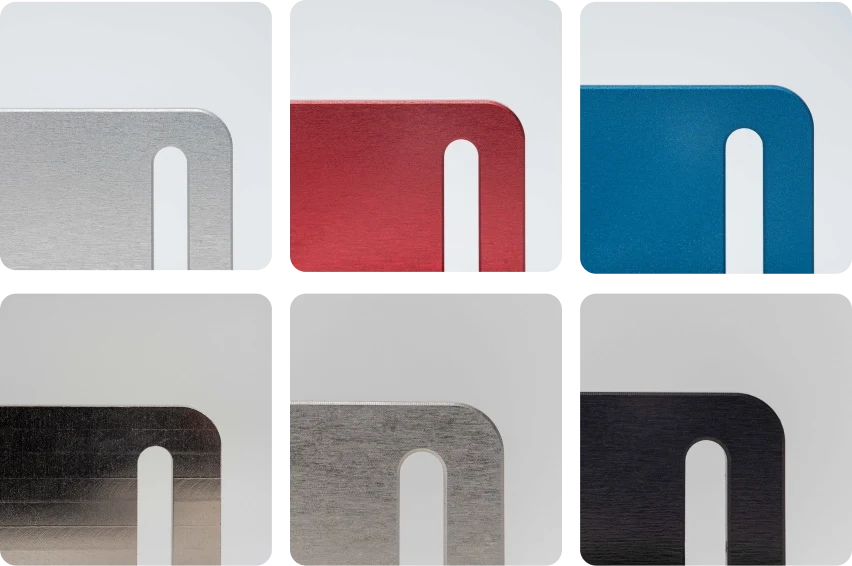
Surface Finishes & Heat Treatment
Surface finishing and heat treatment are specified according to functional needs such as thermal contact, corrosion resistance, wear, appearance, or assembly fit. Define finish type, masking areas, roughness targets, coating thickness effects, hardness requirements, and dimensions to inspect after treatment.
Upload a Drawing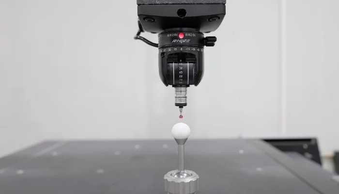
Quality, Metrology & Documentation
Precision inspection, metrology, and quality documentation are planned around drawing-critical dimensions, datums, surface requirements, and agreed acceptance criteria. RFQs should state reporting needs, sampling expectations, material records, revision status, and any customer-specific traceability requirements.
Upload a Drawing
Prototyping & Low-Volume Production
Rapid prototyping and low-volume manufacturing support design validation, thermal-fit checks, tooling trials, engineering changes, and controlled bridge quantities. Submit current drawings, quantities, material requirements, target date, critical dimensions, finishing needs, and the application context affecting manufacturability.
Upload a DrawingMaterial Selection for CNC Machined Heat Sinks
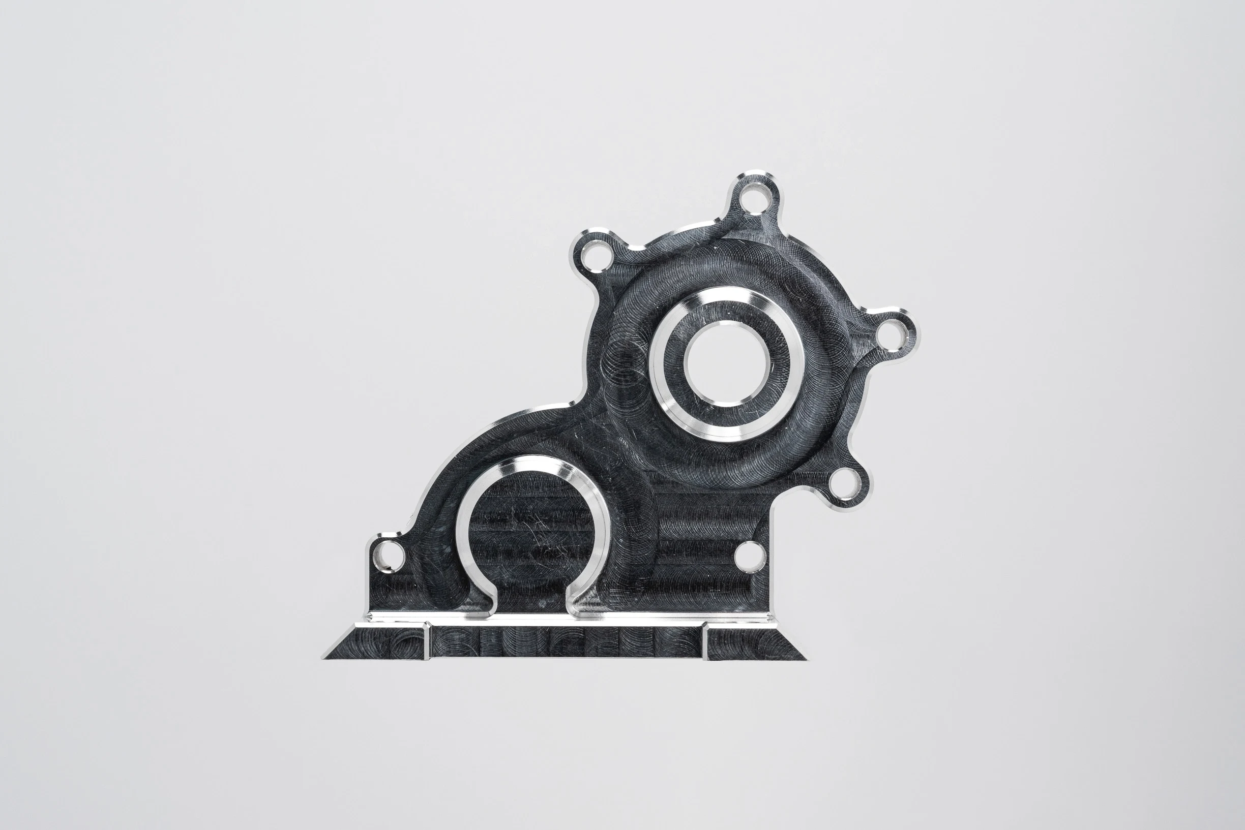
Aluminum Alloys
A common choice for CNC machined heat sinks where low mass, machinability and usable thermal performance must be balanced. Alloy and temper are reviewed against fin geometry, mounting features, surface treatment and inspection requirements.
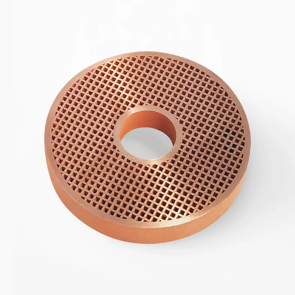
Copper Grades
Copper is considered when rapid heat spreading or higher thermal conductivity is central to the application. Its material behavior, burr-control needs, oxidation protection, part weight and critical contact surfaces require review before machining.
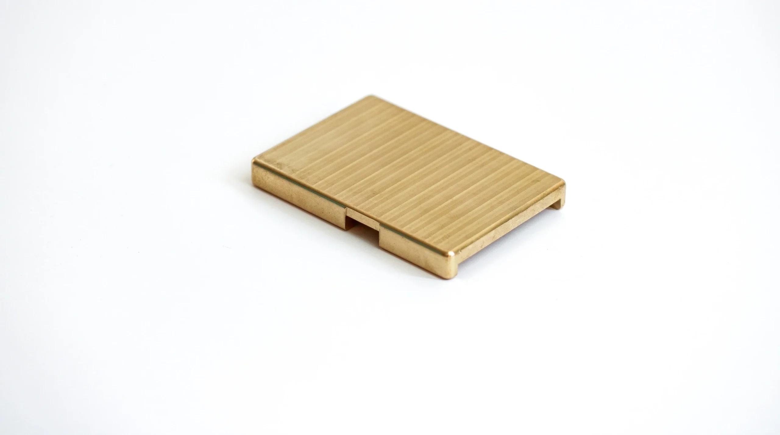
Brass Alloys
Brass may suit thermal parts requiring machinable threaded features, electrical interfaces or integrated fittings. Material grade, thermal duty, plating expectations and dimensional priorities should be defined so the manufacturing route matches the application.
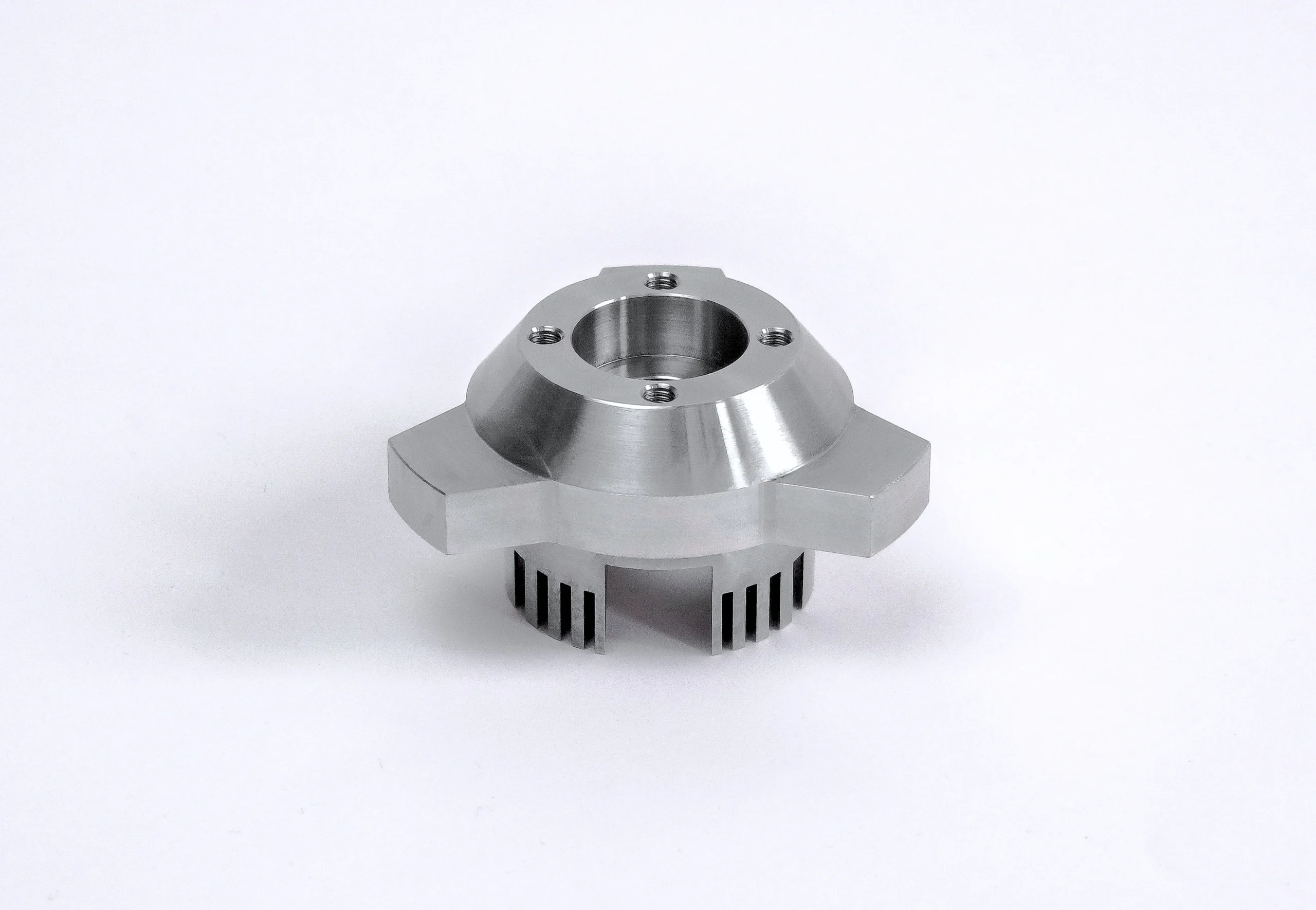
Stainless Steel
Stainless steel is evaluated for assemblies needing corrosion resistance, structural support or durable mounting features alongside thermal components. Its lower thermal conductivity and machining behavior should be weighed against the required heat-transfer path.

Specified Metals
Project-specified metals can be assessed from the drawing, material callout and application context. SUUXIANG reviews availability, machining access, heat-treatment sequence, finishing compatibility and inspection needs before making production commitments.
CNC Machined Heat Sinks: Process Routes
CNC Fin Milling
Milling creates fin arrays, base plates, pockets and mounting features from solid stock. Tool access, fin spacing and depth are reviewed early to help balance thermal surface area, rigidity and practical machining time.
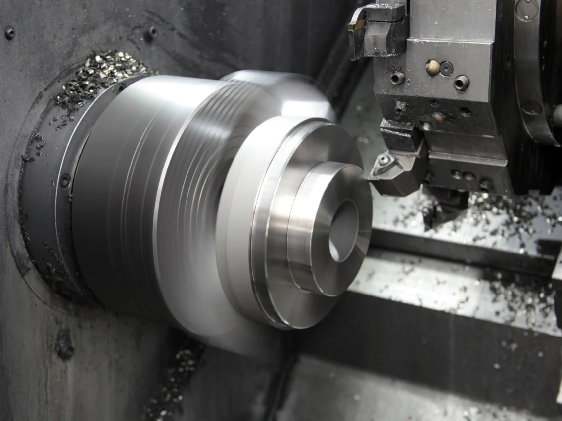
CNC Turning
Turning supports rotational heat-sink features such as cylindrical bodies, threaded interfaces, concentric mounting profiles and precision shoulders. It can establish stable datums before secondary milling or inspection where the drawing calls for them.
Wire EDM
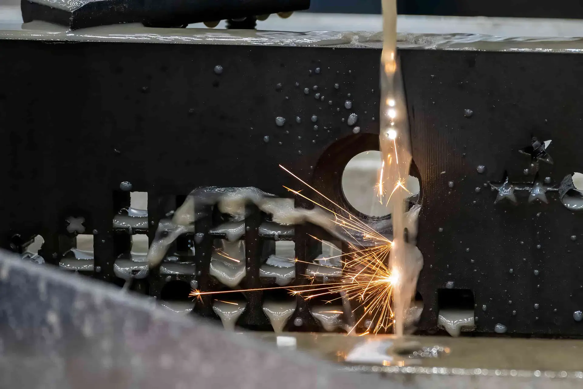
Wire EDM may be considered for precise profiles, narrow internal features or difficult-to-access contours after material condition and design requirements are reviewed. Wire path, start holes and allowable cut locations must be defined from the drawing.
Precision Grinding
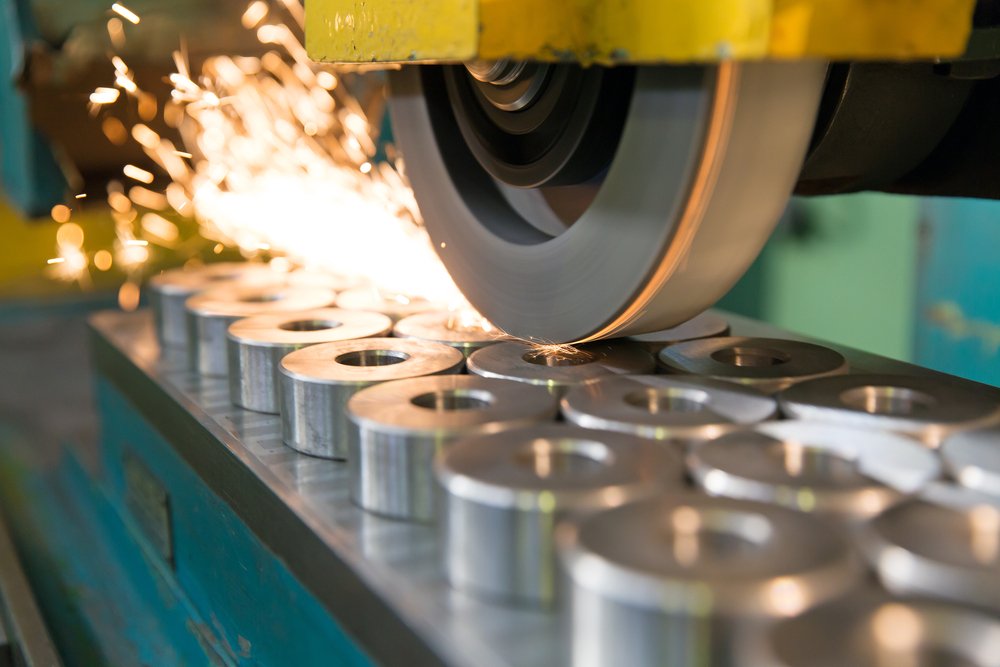
Grinding can refine critical mounting faces, datum surfaces and controlled thickness features when the required finish or dimensional relationship warrants it. Grinding stock, heat-treatment sequence and inspection method should be agreed before production.
Fitting Inspection
Fitting and inspection confirm functional relationships between machined features, hardware interfaces and mating components where applicable. SUUXIANG aligns measurement planning, reporting needs and revision control with the approved order requirements.
CNC Machined Heat Sink Features and Applied Hardware

Mounting Holes
Drilled, reamed or counterbored mounting holes can be positioned to match PCB, chassis or enclosure interfaces. Define hole size, fastener type, datum references and positional requirements for manufacturability and inspection planning.
Threaded Features
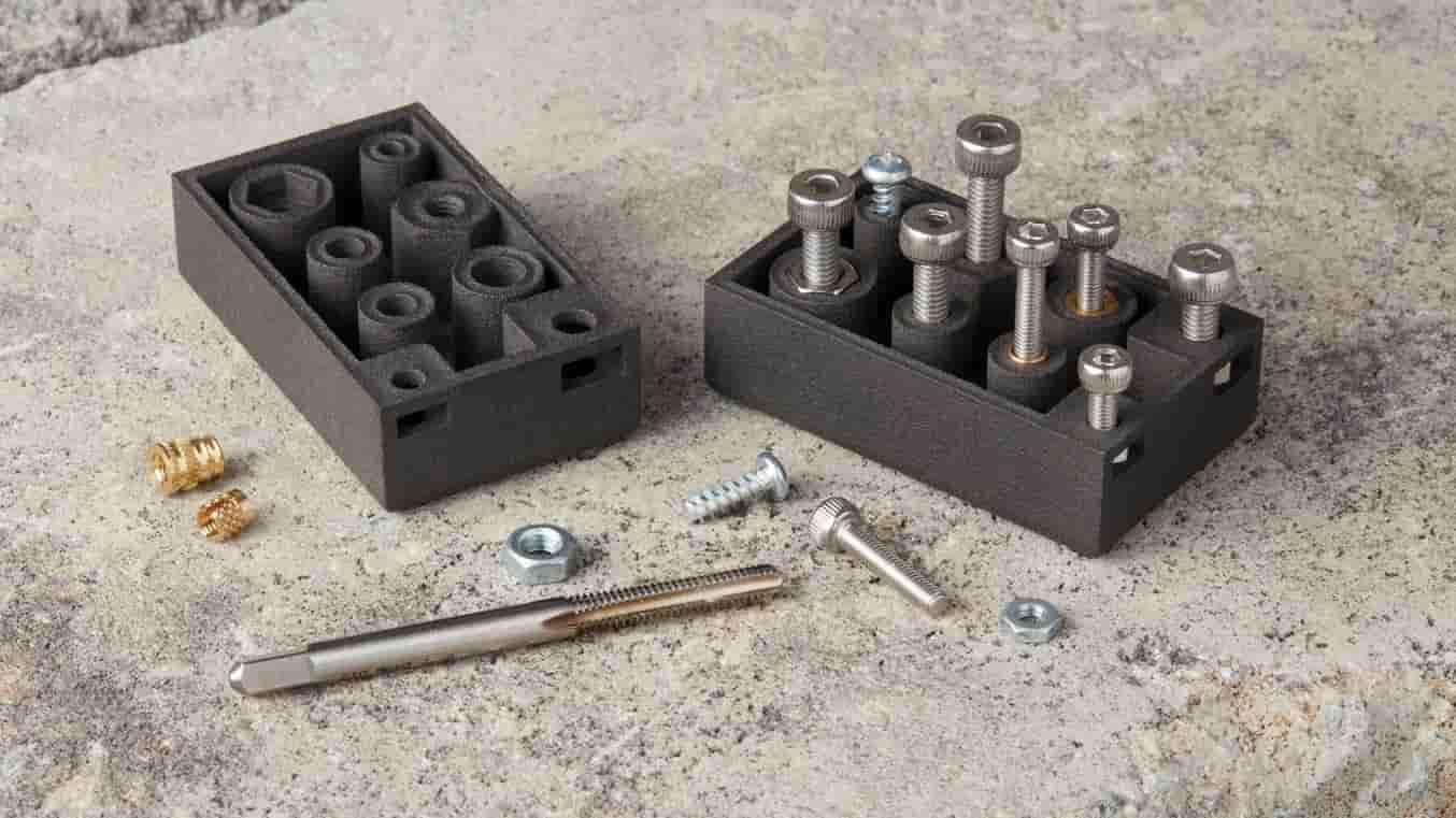
Tapped holes and threaded bosses support direct attachment of fans, covers, boards or thermal modules. Identify thread standard, engagement depth, blind-hole limits and any clearance needed around fins before the machining route is confirmed.
Threaded Inserts
Drawing-specified inserts can provide durable fastening locations where repeated assembly is expected. Insert type, material, installation direction and surrounding wall thickness should be reviewed against heat-sink geometry and the intended assembly method.

Locating Features
Dowel holes, shoulders, slots and locating pockets help establish repeatable position between the heat sink and mating components. Datum strategy, fit requirements and assembly sequence guide machining, grinding and inspection decisions.

Interface Labels
Part markings, identification labels or traceability locations can be allocated where they remain readable without interfering with airflow, mounting faces or critical thermal contact surfaces. Provide content, placement and durability expectations with the RFQ.
Applied Hardware
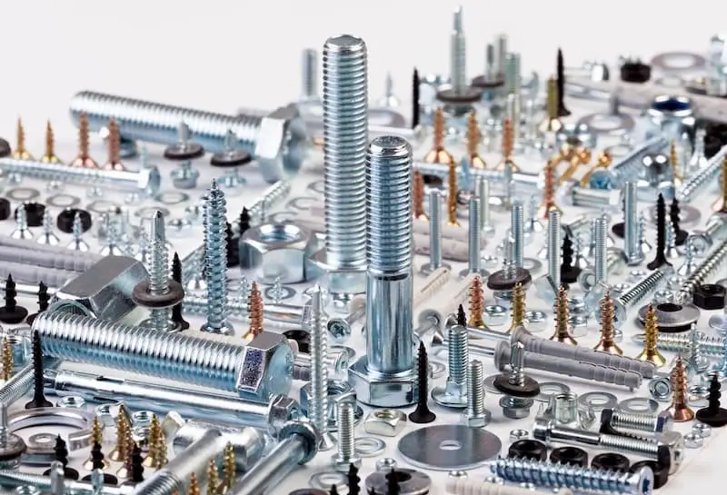
Specified screws, pins, spacers or related hardware may be considered when they support the defined assembly. Supply hardware specifications, mating-part context and required documentation so the scope can be reviewed before any production commitment.
About SUUXIANG Precision Manufacturing
SUUXIANG is the international-facing brand of Dongguan SuuXiang Precision Mold Co., Ltd., established in 2010 in Chang’an Town, Dongguan, Guangdong, China. XiaoCheng Huang is the founder and legal representative. We help global engineering, sourcing, and quality teams turn drawings and specifications into inspected custom parts through a disciplined, drawing-driven workflow.
For CNC machined heat sinks and related precision components, project planning can combine CNC milling and turning, multi-axis machining, EDM, grinding, fitting, and inspection where the verified requirement calls for it. Before quotation or production commitments, we review critical dimensions, datums, material requirements, surface priorities, tool access, and inspection expectations.
Our difference is not an assumed catalogue of standard parts. We focus on configurable, drawing-based work supported by DFM discussion, revision control, process-route decisions, and documentation aligned with the agreed inspection plan. Send the 2D drawing, available 3D model, quantity, material, quality requirements, and delivery target for a practical project review.

From Thermal Design Review to Inspected CNC Machined Heat Sinks
DFM and Datum Review
SUUXIANG reviews drawing-defined CNC-machined heat sinks before quotation, focusing on mounting datums, critical interfaces, fin geometry, tool access, wall stability, and surface requirements. This discussion identifies manufacturability questions early, before process commitments or release to production.
- Confirm mounting faces, hole patterns and functional datums
- Review fin spacing, depth and cutter-access limitations
- Identify heat-treatment, finish and masking requirements
- Align revision status with the RFQ package

Process Route Selection
Heat-sink geometry may require more than standard milling. SUUXIANG evaluates the appropriate combination of CNC machining, EDM, precision grinding and fitting according to feature access, material condition, surface requirements and the dimensions that govern assembly or thermal contact.
- CNC milling for bases, pockets, fins and mounting features
- EDM considered for restricted or intricate feature access
- Grinding planned for controlled contact faces when required
- Process sequence reviewed around material and heat treatment

Critical Dimensions Controlled
For CNC-machined heat sinks, not every dimension carries the same functional risk. SUUXIANG helps define critical dimensions, datum references, and inspection priorities so machining allowances and setups support the mounting plane, fastener locations, and interfaces identified in the drawing.
- Separate critical-to-quality features from general dimensions
- Plan setups around the specified datum structure
- Manage tolerance stack risks at mating interfaces
- Review surface requirements affecting thermal contact
Inspection Records Matched
Inspection planning is tied to the released drawing and order requirements. SUUXIANG coordinates dimensional checks, applicable reporting needs and revision traceability so the supplied documentation corresponds to the agreed inspection method rather than a generic quality statement.
- Align inspection points with drawing callouts
- Confirm reporting and documentation requirements before production
- Keep drawing revisions visible through project coordination
- Match final records to the verified inspection plan
CNC Machined Heat Sinks: SUUXIANG vs. Generic Quoting
For cnc machined heat sinks, compare drawing-led engineering review with a generic price-first quotation process.
← Swipe left or right to view →
Production Workflow for CNC Machined Heat Sinks
Each project moves through documented drawing review, process planning, machining, inspection, and delivery coordination matched to the submitted requirements.
Review RFQ Package
We review the 2D drawing, model, material, quantity, application, critical dimensions, surface requirements, inspection needs, and requested delivery date before quoting.
Plan Manufacturing Route
DFM discussion confirms datums, fin geometry, tool access, mounting features, machining allowances, heat-treatment sequence where specified, and appropriate CNC, EDM, or grinding steps.
Control Revisions and Setup
Approved drawing revisions and production requirements are kept visible as workholding, programs, tools, and in-process checks are prepared for the defined part configuration.
Machine Thermal Components
CNC milling, turning, multi-axis machining, EDM, or grinding are applied as required by the geometry, material, critical features, and agreed manufacturing plan.
Inspect and Document
Finished CNC machined heat sinks are checked against the order-specific inspection plan, with dimensional records and documentation prepared when requested and verified for the project.
Pack and Coordinate Delivery
After final release, parts are packed for the component geometry and shipment requirements, while delivery details and final revision information remain traceable to the order.
Customer Evidence Published Only When Verified
Provide the engineering inputs early so DFM, inspection planning, quotation, and production release can follow a controlled, revision-aware route.
Submit Your Drawing Package
Send the 2D drawing, 3D model when available, application context, quantity, and target delivery date for an initial drawing-based review.
Confirm Critical Requirements
Identify material, heat treatment, critical dimensions, datum references, surface requirements, mounting interfaces, and inspection or reporting expectations before manufacturing commitments are made.
Review DFM and Quotation
Evaluate the proposed machining route, tool access, fin geometry risks, inspection approach, pricing basis, and any sample or first-article requirements with SUUXIANG.
Approve the Production Release
Confirm the controlled revision, agreed requirements, and quality documentation plan before CNC machined heat sinks move into coordinated machining, finishing, inspection, and delivery.
CNC Machined Heat Sinks: Documentation and Certification Evidence
The Complete Buyer’s Guide to CNC-Machined Heat Sinks
No approved, attributable customer feedback is currently available for publication. SUUXIANG reserves this space for verified project outcomes supported by customer permission, drawing revision records, inspection evidence, and agreed delivery documentation.
No verified case outcome is currently approved for this section. Future feedback will identify the applicable drawing-based heat-sink project, manufacturing scope, inspection requirement, and measurable result only when supported by project records and customer authorization.
Customer testimonials are not published until attribution and project evidence are confirmed. For a heat-sink RFQ, share the drawing, material, quantity, critical dimensions, surface requirements, inspection needs, and target delivery date for a documented manufacturing review.
CNC Machined Heat Sinks FAQ
Practical answers for drawing-based sourcing, from RFQ preparation and sampling to inspection, delivery coordination, and documentation.
What information should I send for a CNC machined heat sinks RFQ?
Is there a minimum order quantity for custom CNC machined heat sinks?
Can SUUXIANG provide samples before a larger CNC machined heat sinks order?
When should I choose CNC machining instead of extrusion or die casting for a heat sink?
How should I plan lead time for a custom heat sink project?
What inspection documentation can be discussed for CNC machined heat sinks?
How does SUUXIANG protect drawings and revision-controlled project information?
Can shipping, payment terms, and packaging be confirmed before I place an order?
The Complete Buyer’s Guide to cnc machined heat sinks
Use this decision framework to specify thermal performance, compare CNC manufacturing options, evaluate suppliers, and avoid costly design, sourcing, and launch mistakes for custom cooling components.
1. What Are cnc machined heat sinks?
CNC-machined heat sinks are custom thermal components milled, turned, or otherwise cut from metal stock to carry heat away from an electronic device. Their purpose is to create a controlled conduction-and-convection path, rather than merely add metal around a hot component.
The heat path starts at the semiconductor or power device, crosses a thermal interface material, spreads through the heat-sink base, travels into fins or other exposed features, and then transfers to surrounding air. Contact pressure, interface coverage, base contact area, airflow direction, and available fin surface all influence the result; machining precision alone does not establish thermal performance.
CNC machining is selected when a catalog profile cannot meet the required envelope, mounting pattern, contact geometry, fin layout, or prototype revision needs. It can combine cooling features with mounting and enclosure interfaces without dedicated forming tooling, while extrusion remains limited to a constant cross-section (https://jlccnc.com/blog/cnc-heat-sink-manufacturing). For buyers, a machined heat sink solves a fit-and-heat-path problem that must be verified against the assembly and operating conditions.
2. Evolution of cnc machined heat sinks
Extrusion made simple passive metal profiles economical when a constant cross-section could serve the airflow and mounting arrangement. Casting later enabled more three-dimensional shapes, but tooling and alloy choices must be evaluated against the application rather than treated as universal upgrades. Source: https://jlccnc.com/blog/cnc-heat-sink-manufacturing
Bonded-fin assemblies expanded surface-area options by joining fins to a base, while skiving formed thin fins from a solid block for certain geometries. Both routes remain process-specific: fin geometry, joint requirements, material, airflow direction, and expected volume determine whether either route is practical.
CNC machining became more relevant as power-dense electronics moved into compact assemblies requiring prototype iteration, nonstandard envelopes, and integrated mounting faces, holes, pockets, or locating features. For cnc machined heat sinks, the drawing review should balance thermal intent with tool access, achievable fin geometry, datum control, and inspection requirements before selecting the manufacturing route. Source: https://jlccnc.com/blog/cnc-heat-sink-manufacturing
3. Types of cnc machined heat sinks
Five common architectures establish the thermal and manufacturing starting point for cnc machined heat sinks. Select one from the enclosure airflow, heat-source footprint, mounting interfaces, and whether a future liquid loop is plausible.
| Architecture | Airflow Assumption | Machining Focus | Typical Use |
|---|---|---|---|
| Straight-fin | Directional forced flow | Deep-slot tool access | Fans and ducted electronics |
| Pin-fin | Mixed or low-direction flow | Field spacing and rigidity | Compact enclosures |
| Radial | Omnidirectional flow | Multi-axis access | LED or circular packages |
| Integrated baseplate | Depends on fin layout | Datums and interfaces | PCB or power-module mounts |
| Liquid-ready block | Coolant loop planned | Channels and sealing faces | High heat-flux assemblies |
Directional Fin Arrays
Straight fins suit forced airflow with a known inlet-to-outlet path. Parallel channels are efficient to program, but fin height, cutter reach, chip evacuation, and rigidity must be reviewed together.
Pin And Radial Fields
Pin fins and radial fields suit uncertain or multidirectional airflow. Their distributed surface area helps compact enclosures, while dense fields increase machining time and may restrict airflow if spacing is not thermally validated.
Integrated And Liquid-Ready Bases
Baseplates can combine mounting bosses, pockets, and alignment features in one datum scheme. Liquid-ready blocks require early agreement on channel geometry, sealing faces, ports, pressure testing, and inspection evidence.
4. Materials for cnc machined heat sinks
6061 aluminum, copper, and aluminum-copper assemblies solve different thermal and mechanical problems. For cnc machined heat sinks, shortlist material against the interface, airflow, mounting scheme, environment, and allowable mass—not conductivity alone.
| Material Route | Thermal Performance | Weight And Machining | Corrosion And Finish | Verify Before RFQ |
|---|---|---|---|---|
| 6061 aluminum | Good | Low weight; favorable machining | Anodizing compatible | Base thickness; thread loads |
| 6063 aluminum | Good | Low weight; machinability varies by form | Anodizing compatible | Available stock form; geometry |
| Copper | Very high | Heavy; slower machining | Oxidizes; coating choice matters | Mass; tool wear; mounting |
| Aluminum-copper assembly | Targeted spreading | Mixed machining and joining | Galvanic isolation required | Joint method; CTE; environment |
Start With Assembly Loads
6061-T6 is commonly selected when threaded mounting features, low mass, and practical milling matter. Verify clamp load, contact-area flatness, galvanic pairing, and whether the enclosure shares heat-spreading duty.
Use Copper Selectively
Copper improves local heat spreading but adds weight, material cost, and machining difficulty. Verify tool access, fastener loading, oxidation exposure, and whether a copper insert or base is more economical than a full copper part.
5. Finishes and customization options
CNC-machined features should earn their place by improving thermal-path integration, mounting repeatability, or assembly access. Separate functional requirements from appearance requirements before RFQ release.
| Option | Useful When | Drawing Requirement |
|---|---|---|
| Anodizing | Noncontact corrosion protection or appearance | Color, standard, masked faces |
| Conversion coating | Electrical continuity or paint preparation | Specification and coverage |
| Laser marking | Traceable identification | Location, content, contrast limit |
| Captive hardware | Repeated service assembly | Fastener, installation side, pull-out requirement |
Functional Machining Features
Mounting-hole patterns, PCB pockets, cable channels, and captive-hardware provisions can eliminate secondary brackets or prevent assembly misalignment. Show mating-part interfaces, fastener size, thread engagement, datum references, and keep-out zones on the drawing.
Thermal contact faces need uninterrupted bearing area where possible. Put logos, deep engraving, and nonessential pockets outside the interface plane; interruptions can complicate flatness control and thermal-interface-material coverage.
Finish And Masking Notes
Anodizing, conversion coating, and cosmetic marking serve different purposes and should be called out by specification, color, coverage, and masking boundary. Identify every thermal-contact, grounding, threaded, press-fit, or bonded surface that must remain uncoated or receive a defined finish.
Drawing notes should state whether finish occurs before hardware installation. Include permitted touch-up, marking location and legibility requirements, plus the inspection method for any appearance-critical surface.
Value Versus Complexity
Useful options support a verified integration need: repeatable mounting, protected noncontact surfaces, identification, or simplified assembly. Avoid decorative machining on contact faces and finish callouts with no environmental, electrical, or cosmetic acceptance criterion.
6. Critical design and quality elements
Heat-sink performance is set as much by machinable geometry and interface control as by surface area. A drawing review should link thermal intent, airflow, datums, tolerances, and inspection methods before the process route is released.
Fin Geometry And Airflow
Fin thickness, spacing, and height must suit the cutter diameter, material rigidity, and intended airflow direction. Long, narrow channels restrict tool access and chip evacuation; thin unsupported fins also raise chatter and burr risk.
3-axis milling favors fin fields accessible from one direction, while cross-flow or pin patterns may require extra setups. Specify the airflow path and keep clearance for coolant and chip removal.
Base And Interface Control
The base is the thermal and mechanical interface, so thickness, flatness, and finish belong on the mating region rather than every face. A datum scheme should locate mounting holes and contact pads from the same functional reference.
±0.05 mm is a common example of a locally controlled mounting interface, but the drawing must state the actual application need. Broad tight tolerances increase machining and inspection effort without improving fit.
DFM And Inspection Planning
Before production, SUUXIANG reviews critical dimensions, tool reach, burr-control edges, machining allowances, and the inspection plan against the drawing revision. CMM, height-gage, or surface-plate methods should be assigned to the features that affect assembly or thermal contact.
100% checks are most useful for defined critical features; sampling should follow the agreed quality requirement. Final records should match the approved revision and order-specific inspection plan.
7. How to choose a heat-sink manufacturer
Two comparable quotations can conceal very different engineering controls. Evaluate cnc machined heat sinks through project evidence: drawing review, traceable inputs, inspection records, finishing coordination, and shipment protection.
| Evaluation Area | Evidence To Request | Decision Question |
|---|---|---|
| Material | Certificate or lot traceability | Can the supplied grade be linked to the order? |
| Machining | DFM notes and process route | Are fin access and datum risks addressed? |
| Inspection | Method and result format | Which critical features are measured? |
| Finishing | Specification and coordination plan | How is finish protected after inspection? |
| Packaging | Part-specific packing proposal | How are fins and contact faces protected? |
Request A DFM Response
Within 1–2 working days, a useful DFM response should identify fin-tool access, workholding, burr risks, datum interpretation, and any tolerance or flatness conflict. Ask for annotated feedback rather than a generic capability statement.
- 2D drawing with GD&T and revision
- 3D model in STEP or native format
- Thermal load, airflow, interface and mounting context
- Forecast quantities, target date and inspection needs
Verify Production Evidence
Before release, match each claim to order-specific evidence. Confirm material identification, process route, in-process controls, final inspection method, finish requirement, revision status, and packing plan.
Compare Supplier Answers
Three questions expose execution maturity: Which dimensions receive inspection, how are revisions controlled, and what documentation ships with each lot? For prototype-to-low-volume work, request the same answer at each quantity tier.
8. Common cnc machined heat sinks mistakes
Eight pre-RFQ checks catch avoidable thermal and manufacturing risks before a drawing reaches the shop. For cnc machined heat sinks, specify performance, interfaces, and inspection priorities together.
Material And Fin Choices
Two material errors recur: choosing conductivity alone can ignore weight, corrosion, cost, and machining behavior; overpacked fins can restrict chip evacuation and airflow. State the operating environment, mass limit, fin spacing, and thermal target, then review the material and fin route with the supplier.
Airflow And Contact Faces
Three interface omissions cause weak results: ignoring airflow, applying cosmetic texture to a contact face, and omitting flatness. Provide fan direction or natural-convection orientation, reserve the mating plane for functional finish, and define flatness, datum, TIM, and inspection method.
Drawing And Validation Control
Three sourcing failures raise cost or delay release: tolerancing noncritical geometry, designing without fixture access, and skipping prototype validation. Mark CTQ dimensions and datums, ask for a fixturing and tool-access review, then validate prototype thermal behavior and fit before production approval.
9. Steps from design to production
A controlled launch for cnc machined heat sinks moves through defined technical gates, not a quote alone. The buyer owns application requirements; SUUXIANG confirms manufacturability, inspection planning, and revision traceability.
Define The Thermal Basis
Gate 1 records heat load, ambient range, airflow, orientation, interface material, mounting load, and allowable device temperature. The buyer supplies operating and mating-part data.
Gate 2 releases a thermal model and geometry concept. The buyer approves predicted performance assumptions before detailed manufacturing work.
Release Design And DFM
Gate 3 packages a controlled 2D drawing, 3D CAD, material, finish, datums, critical dimensions, quantity, and revision identifier. SUUXIANG reviews tool access, fixturing, fin stability, and inspection access.
Gate 4 closes DFM comments in writing. Changes to geometry, tolerances, or inspection method require buyer approval and a revised document set.
Prove And Control Production
Gate 5 uses a prototype to compare dimensions, flatness, assembly fit, and thermal test results against the buyer’s acceptance criteria. SUUXIANG supplies inspection evidence defined by the agreed plan.
Gate 6 approves the first article and locks the specification package. Repeat or low-volume orders should reference the approved revision, reporting requirements, quantity, and delivery schedule.
10. CNC heat-sink pricing and lead times
Three cost layers govern custom cnc machined heat sinks: raw-material utilization, programmed machine time, and quality/handling work. Aluminum versus copper, billet size, fin depth and density, tool reach, workholding setups, tight datum-related tolerances, inspection reporting, finishing, quantity, and protective packaging can each change the quoted route.
One DFM review before release can reduce total cost by combining separate mounting features into the heat-sink body, standardizing radii and fasteners, widening impractical fin gaps, and reducing reorientations. Confirm thermal performance and mating-interface requirements before relaxing any geometry or surface specification.
Repeat-order economics improve when the released drawing, revision, inspection plan, packing method, and machining strategy remain stable. SUUXIANG should quote lead time only after reviewing material availability, process sequence, finishing, inspection scope, and delivery destination.
| Quantity tier | Illustrative planning lead time | Primary cost-driver notes |
|---|---|---|
| Prototype: 1–10 | Typically 1–3 weeks after technical review | Programming, setups, material, first-article inspection |
| Low volume: 11–100 | Typically 2–5 weeks | Cycle time, fixture approach, tolerance and finish requirements |
| Repeat order: 101+ | Project-specific confirmation | Stable setup, batch size, inspection sampling, packaging and logistics |
Upload Your CNC Machined Heat Sinks Drawing
Include material, quantity, critical dimensions, surface requirements, inspection needs, and target delivery date for a disciplined RFQ review.